 | ÐлекÑÑоннÑй компоненÑ: BQ2011J | СкаÑаÑÑ:  PDF PDF  ZIP ZIP |
Gas Gauge IC for High Discharge Rates (Rev. A)

Features
Conservative and repeatable
measurement of available charge
in rechargeable batteries
Designed for portable equipment
such as power tools with high dis-
charge rates
Designed for battery pack inte-
gration
-
120
µA typical standby current
(self-discharge estimation mode)
-
Small size enables imple-
mentations in as little as
1
2
square inch of PCB
Direct drive of LEDs for capacity
display
Self-discharge compensation us-
ing internal temperature sensor
Simple single-wire serial commu-
nications port for subassembly
testing
16-pin narrow SOIC
General Description
The bq2011 Gas Gauge IC is intended
for battery-pack installation to main-
tain an accurate record of available
battery charge. The IC monitors a
voltage drop across a sense resistor
connected in series between the nega-
tive battery terminal and ground to
determine charge and discharge ac-
tivity of the battery. The bq2011 is
designed for systems such as power
tools with very high discharge rates.
Battery self-discharge is estimated
based on an internal timer and tem-
perature sensor. Compensations for
battery temperature and rate of
charge or discharge are applied to
t h e c h a r g e , d i s c h a r g e , a n d
selfdischarge calculations to provide
available charge information across
a wide range of operating conditions.
Initial battery capacity is set using
the PFC and MODE pins.
Actual
battery capacity is automatically
"learned" in the course of a dis-
charge cycle from full to empty and
may be displayed depending on the
display mode.
Nominal available charge may be di-
rectly indicated using a five-seg-
ment LED display. These segments
are used to indicate graphically the
nominal available charge.
The bq2011 supports a simple single-
line bidirectional serial link to an exter-
nal processor (common ground). The
bq2011 outputs battery information in
response to external commands over the
serial link. To support subassembly
testing, the outputs may also be con-
trolled by command. The external proc-
essor may also overwrite some of the
bq2011 gas gauge data registers.
The bq2011 may operate directly
from four cells. With the REF output
and an external transistor, a simple,
inexpensive regulator can be built to
provide V
CC
from a greater number
of cells.
Internal registers include available
charge, temperature, capacity, battery
ID, and battery status.
1
Gas Gauge IC for
High Discharge Rates
2/96 E
Pin Connections
Pin Names
1
PN201101.eps
16-Pin Narrow SOIC
2
3
4
5
6
7
8
16
15
14
13
12
11
10
9
VCC
REF
NC
DQ
RBI
SB
DISP
SR
MODE
SEG1
SEG2
SEG3
SEG4
SEG5
PFC
VSS
MODE
Display mode output
SEG
1
LED segment 1
SEG
2
LED segment 2
SEG
3
LED segment 3
SEG
4
LED segment 4
SEG
5
LED segment 5
PFC
Programmed full count
selection input
REF
Voltage reference output
NC
No connect
DQ
Serial communications
input/output
RBI
Register backup input
SB
Battery sense input
DISP
Display control input
SR
Sense resistor input
V
CC
3.06.5V
V
SS
Negative battery terminal
bq2011

Pin Descriptions
MODE
Display mode output
When left floating, this output selects rela-
tive mode for capacity display. If connected
to the anode of the LEDs to source current,
absolute mode is selected for capacity dis-
play. See Table 1.
SEG
1
SEG
5
LED display segment outputs
Each output may activate an LED to sink
the current sourced from MODE, the bat-
tery, or V
CC
.
PFC
Programmed full count selection input
This three-level input pin defines the pro-
grammed full count (PFC) thresholds and
scale selections described in Table 1.
The
state of the PFC pin is only read immediate-
ly after a reset condition.
SR
Sense resistor input
The voltage drop (V
SR
) across the sense re-
sistor R
S
is monitored and integrated over
time to interpret charge and discharge activ-
ity. The SR input is tied to the low side of
the sense resistor. V
SR
> V
SS
indicates dis-
charge, and V
SR
< V
SS
indicates charge. The
effective voltage drop, V
SRO
, as seen by the
bq2011 is V
SR
+ V
OS
(see Table 3).
NC
No connect
DISP
Display control input
DISP floating allows the LED display to
be active during charge and discharge if
V
SRO
< -1mV (charge) or V
SRO
> 2mV (dis-
charge).
Transitioning DISP low activates
the display for 4
± 0.5 seconds.
SB
Secondary battery input
This input monitors the single-cell voltage
potential through a high-impedance resis-
tive divider network for the end-of-discharge
voltage (EDV) threshold and maximum cell
voltage (MCV).
RBI
Register backup input
This input is used to provide backup potential
to the bq2011 registers during periods when
V
CC
3V. A storage capacitor should be con-
nected to RBI.
DQ
Serial I/O pin
This is an open-drain bidirectional pin.
REF
Voltage reference output for regulator
REF provides a voltage reference output for
an optional micro-regulator.
V
CC
Supply voltage input
V
SS
Ground
2
bq2011
Functional Description
General Operation
The bq2011 determines battery capacity by monitoring
the amount of charge input to or removed from a re-
chargeable battery. The bq2011 measures discharge and
charge currents, estimates self-discharge, monitors the
battery for low-battery voltage thresholds, and compen-
sates for temperature and charge/discharge rates. The
charge measurement is made by monitoring the voltage
across a small-value series sense resistor between the
negative battery terminal and ground.
The available
battery charge is determined by monitoring this voltage
over time and correcting the measurement for the envi-
ronmental and operating conditions.
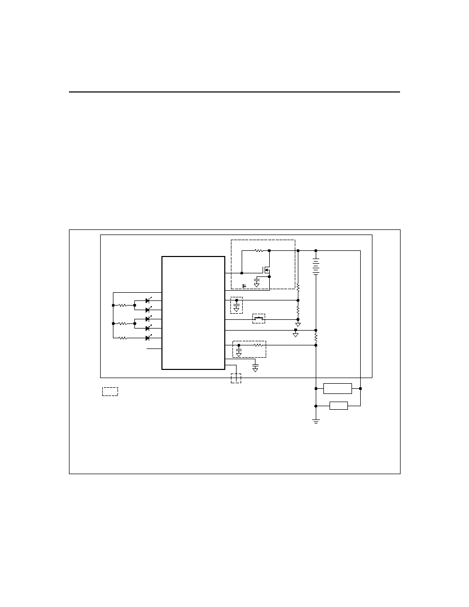
Figure 1 shows a typical battery pack application of the
bq2011 using the LED display with absolute mode as a
charge-state indicator. The bq2011 can be configured to
display capacity in either a relative or an absolute dis-
play mode.
The relative display mode uses the last
measured discharge capacity of the battery as the bat-
tery "full" reference. The absolute display mode uses the
programmed full count (PFC) as the full reference, forc-
ing each segment of the display to represent a fixed
amount of charge.
A push-button display feature is
available for momentarily enabling the LED display.
The bq2011 monitors the charge and discharge currents
as a voltage across a sense resistor (see R
S
in Figure 1).
A filter between the negative battery terminal and the
SR pin may be required if the rate of change of the bat-
tery current is too great.
3
bq2011
FG201101.eps
PFC
SEG5
SEG4
SEG3
SEG2
SEG1
VSS
DISP
SB
VCC
REF
bq2011
Gas Gauge IC
MODE
SR
RBI
DQ
VCC
C1
0.1 F
Q1
ZVNL110A
R1
RS
RB1
RB2
Load
Charger
Indicates optional.
Directly connect to VCC across 4 cells (4.8V nominal and should not
exceed 6.5V) with a resistor and a Zener diode to limit voltage during charge.
Otherwise, R1, C1, and Q1 are needed for regulation of >4 cells.
Programming resistors and ESD-protection diodes are not shown.
R-C on SR may be required, (application-specific), where the maximum
R should not exceed 20K.
Figure 1. Battery Pack Application Diagram--LED Display,
Absolute Mode

Register Backup
The bq2011 RBI input pin is intended to be used with a
storage capacitor to provide backup potential to the inter-
nal bq2011 registers when V
CC
momentarily drops below
3.0V. V
CC
is output on RBI when V
CC
is above 3.0V.
After V
CC
rises above 3.0V, the bq2011 checks the inter-
nal registers for data loss or corruption.
If data has
changed, then the NAC and FULCNT registers are
cleared, and the LMD register is loaded with the initial
PFC.
Voltage Thresholds
In conjunction with monitoring V
SR
for charge/discharge
currents, the bq2011 monitors the single-cell battery po-
tential through the SB pin. The single-cell voltage po-
tential is determined through a resistor-divider network
per the following equation:
RB
RB
N
1
2
1
=
-
where N is the number of cells, RB
1
is connected to the
positive battery terminal, and RB
2
is connected to the
negative battery terminal. The single-cell battery volt-
age is monitored for the end-of-discharge voltage (EDV)
and for maximum cell voltage (MCV). The EDV thresh-
old level is used to determine when the battery has
reached an "empty" state, and the MCV threshold is used
for fault detection during charging. The EDV and MCV
thresholds for the bq2011 are fixed at:
V
EDV
= 0.90V
V
MCV
= 2.00V
During discharge and charge, the bq2011 monitors V
SR
for various thresholds, V
SR1
V
SR4
. These thresholds are
used to compensate the charge and discharge rates. Ref-
er to the discharge compensation section for details.
EDV monitoring is disabled if V
SR
> V
SR1
(50mV typical)
and resumes 1 second after V
SR
drops back below V
SR1
.
Reset
The bq2011 recognizes a valid battery whenever V
SB
is
greater than 0.1V typical. V
SB
rising from below 0.25V
resets the device. Reset can also be accomplished with a
command over the serial port as described in the Reset
Register section.
Temperature
The bq2011 internally determines the temperature in
10°C steps centered from -35°C to +85°C. The tempera-
ture steps are used to adapt charge and discharge rate
compensations, self-discharge counting, and available
charge display translation.
The temperature range is
available over the serial port in 10°C increments as
shown below:
Layout Considerations
The bq2011 measures the voltage differential between
the SR and V
SS
pins. V
OS
(the offset voltage at the SR
pin) is greatly affected by PC board layout. For optimal
results, the PC board layout should follow the strict rule
of a single-point ground return. Sharing high-current
ground with small signal ground causes undesirable
noise on the small signal nodes. Additionally:
n
The capacitors (SB and V
CC
) should be placed as close
as possible to the SB and V
CC
pins, respectively, and
their paths to V
SS
should be as short as possible. A
high-quality ceramic capacitor of 0.1
µf is recommended
for V
CC
.
n
The sense resistor (R
S
) should be as close as possible
to the bq2011.
n
The R-C on the SR pin should be located as close as
possible to the SR pin. The maximum R should not
exceed 20K.
4
bq2011
TMPGG (hex)
Temperature Range
0x
< -30°C
1x
-30°C to -20°C
2x
-20°C to -10°C
3x
-10°C to 0°C
4x
0°C to 10°C
5x
10°C to 20°C
6x
20°C to 30°C
7x
30°C to 40°C
8x
40°C to 50°C
9x
50°C to 60°C
Ax
60°C to 70°C
Bx
70°C to 80°C
Cx
> 80°C
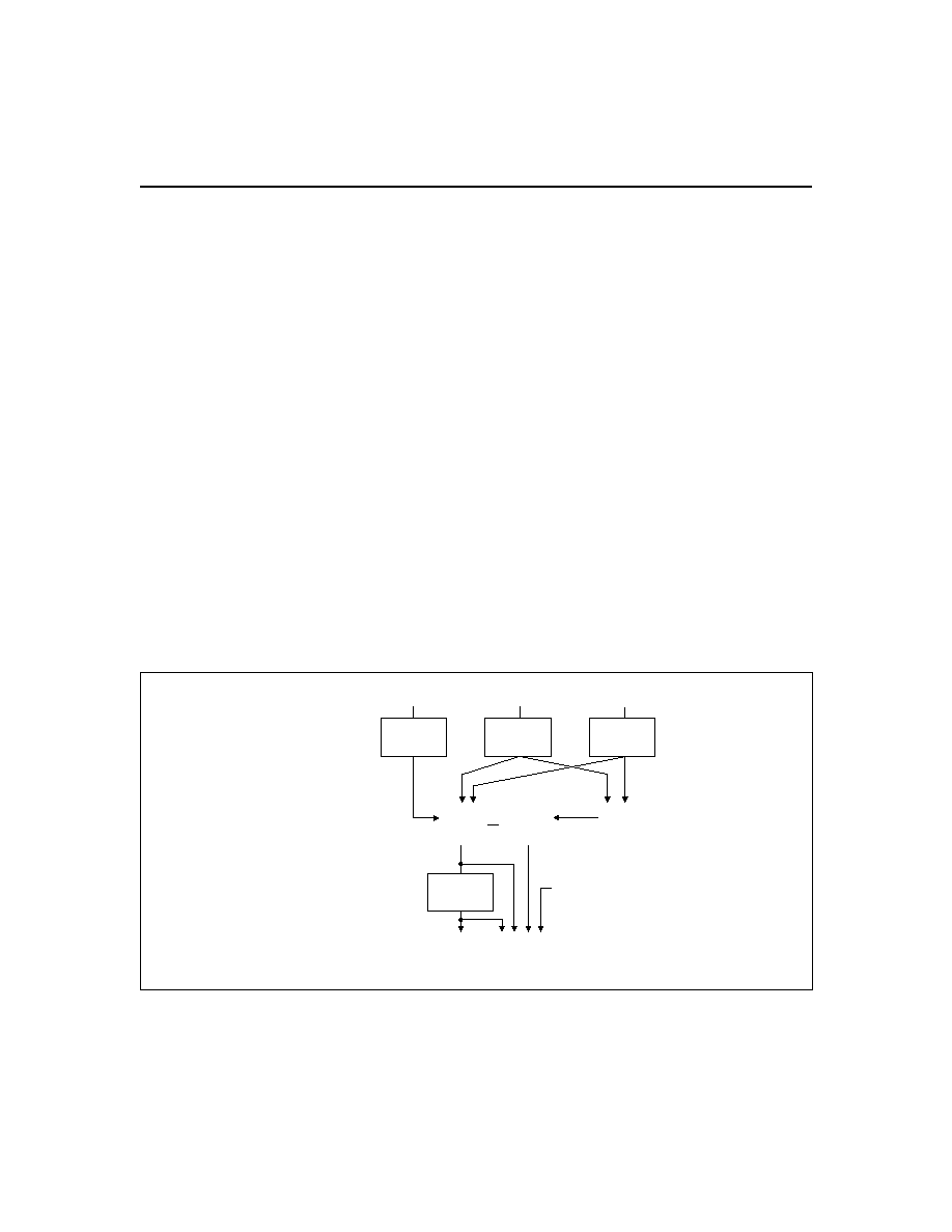
Gas Gauge Operation
The operational overview diagram in Figure 2 illustrates
the operation of the bq2011. The bq2011 accumulates a
measure of charge and discharge currents, as well as an
estimation of self-discharge. Charge and discharge cur-
rents are temperature and rate compensated, whereas
self-discharge is only temperature compensated.
The main counter, Nominal Available Charge (NAC),
represents the available battery capacity at any given
time.
Battery charging increments the NAC register,
while battery discharging and self-discharge decrement
the NAC register and increment the DCR (Discharge
Count Register).
The Discharge Count Register (DCR) is used to update
the Last Measured Discharge (LMD) register only if a
complete battery discharge from full to empty occurs
without any partial battery charges.
Therefore, the
bq2011 adapts its capacity determination based on the
actual conditions of discharge.
The battery's initial capacity is equal to the Pro-
grammed Full Count (PFC) shown in Table 1.
Until
LMD is updated, NAC counts up to but not beyond this
threshold during subsequent charges. This approach al-
lows the gas gauge to be charger-independent and com-
patible with any type of charge regime.
1.
Last Measured Discharge (LMD) or
learned battery capacity:
LMD is the last measured discharge capacity of the
battery. On initialization (application of V
CC
or bat-
tery replacement), LMD = PFC. During subsequent
discharges, the LMD is updated with the latest
measured capacity in the Discharge Count Register
(DCR) representing a discharge from full to below
EDV. A qualified discharge is necessary for a ca-
pacity transfer from the DCR to the LMD register.
The LMD also serves as the 100% reference thresh-
old used by the relative display mode.
2.
Programmed Full Count (PFC) or initial
battery capacity:
The initial LMD and gas gauge rate values are pro-
grammed by using PFC. The PFC also provides the
100% reference for the absolute display mode. The
bq2011 is configured for a given application by se-
lecting a PFC value from Table 1. The correct PFC
may be determined by multiplying the rated bat-
tery capacity in mAh by the sense resistor value:
Battery capacity (mAh) * sense resistor () =
PFC (mVh)
Selecting a PFC slightly less than the rated capac-
ity for absolute mode provides capacity above the
full reference for much of the battery's life.
5
bq2011
FG201104.eps
Temperature
Compensation
Charge
Current
Discharge
Current
Self-Discharge
Timer
Temperature
Translation
Nominal
Available
Charge
(NAC)
Last
Measured
Discharged
(LMD)
Discharge
Count
Register
(DCR)
<
Qualified
Transfer
+
Rate and
Temperature
Compensation
Rate and
Temperature
Compensation
Temperature Step,
Other Data
+
-
Inputs
Main Counters
and Capacity
Reference (LMD)
Outputs
Serial
Port
Chip-Controlled
Available Charge
LED Display
-
+
Rate and
Temperature
Compensation
Figure 2. Operational Overview