 | ÐлекÑÑоннÑй компоненÑ: BQ2052 | СкаÑаÑÑ:  PDF PDF  ZIP ZIP |
Äîêóìåíòàöèÿ è îïèñàíèÿ www.docs.chipfind.ru

1
Features
Accurate measurement of avail-
able capacity in Lithium primary
batteries such as Lithium Sul-
phur Dioxide and Lithium Man-
ganese Dioxide
Provides a low-cost battery moni-
tor solution for pack integration
-
Complete circuit can fit less
than 1 square inch of PCB
space
-
Low operating current
-
Less than 100nA of data
retention current
Single-wire communication inter-
face (HDQ bus) for critical battery
parameters
Communicates remaining capac-
ity with direct drive of LEDs in 3
selectable modes
Measurements automatically
compensated for discharge rate
and temperature
16-pin narrow SOIC
General Description
The bq2052 Lithium Primary Gas
G a u g e I C i s i n t e n d e d f o r b a t-
tery-pack or in-system installation
to maintain an accurate record of
available battery capacity.
The IC
monitors a voltage drop across a
sense resistor connected in series
with the cells to determine dis-
charge activity of the battery. The
bq2052 applies compensations for
battery temperature and discharge
rate to the available charge counter
to provide available capacity infor-
mation across a wide range of oper-
ating conditions.
Compensated available capacity
may be directly indicated using an
LED display.
The LED display is
programmable and can be config-
ured as two, four, or five segments.
These segments are used to depict
available battery capacity.
The
bq2052 supports a single-wire serial
communications link to an external
micro-controller.
The link allows
the micro-controller to read and
write the internal registers of the
bq2052.
The internal registers in-
clude available battery capacity,
voltage, temperature, current, and
battery status. The controller may
also overwrite some of the bq2052
gas gauge data registers.
The bq2052 can operate from the
batteries in the pack. The REF out-
put and an external FET provide a
simple, inexpensive voltage regula-
tor to supply power to the circuit
from the cells.
Preliminary
bq2052
LCOM
LED common output
SEG
1
/PROG
1
LED segment 1/
program 1 input
SEG
1
/PROG
2
LED segment 2/
program 2 input
SEG
1
/PROG
3
LED segment 3/
program 3 input
SEG
1
/PROG
4
LED segment 4/
program 4 input
SEG
1
/PROG
5
LED segment 5/
program 5 input
CP
Control port
1
PN2052H1.eps
16-Pin Narrow SOIC
2
3
4
5
6
7
8
16
15
14
13
12
11
10
9
VCC
REF
PROG6
HDQ
RBI
SB
DISP
SR
LCOM
SEG1/PROG1
SEG2/PROG2
SEG3/PROG3
SEG4/PROG4
SEG5/PROG5
CP
VSS
Pin Connections
SLUS019MAY 1999
Gas Gauge IC
for Lithium Primary Cells
Pin Names
V
SS
System ground
SR
Sense resistor input
DISP
Display control input
SB
Battery sense input
RBI
Register backup input
HDQ
Serial communications
input/output
PROG
6
Program 6 input
REF
Voltage reference output
V
CC
Supply voltage

Pin Descriptions
LCOM
LED common output
This open-drain output switches V
CC
to
source current for the LEDs. The switch is
off during initialization to allow reading of
the soft pull-up or pull-down program resis-
tors. LCOM is also high impedance when the
display is off.
SEG
1
SEG
5
LED display segment outputs (dual func-
tion with PROG
1
PROG
5
)
Each output may activate an LED to sink
the current sourced from LCOM.
PROG
1
PROG
2
Programmed full count selections
These three-level input pins define the pro-
grammed full count.
PROG
3
Power gauge scale selection inputs (dual
function with SEG
3
SEG
4
)
This three-level input pin defines the scale
factor.
PROG
4
Programmed compensation factors
This three-level input pin defines the bat-
tery discharge compensation factors.
PROG
5
Programmed display mode
This three-level input pin defines the capac-
ity indication display mode.
PROG
6
Programmed initial capacity state
This input defines the initial battery capac-
ity indication state. When tied to V
CC
, the
bq2052 sets the available capacity to full on
reset. When tied to V
SS
, the bq2052 sets the
available capacity to zero on reset.
V
SS
Ground
SR
Sense resistor input
The voltage drop (V
SR
) across the sense resis-
tor R
S
is monitored and integrated over time
to interpret discharge activity. V
SR
> V
SS
in-
dicates discharge. The effective voltage drop,
V
SRO
, as seen by the bq2052 is V
SR
+ V
OS
.
DISP
Display control input
DISP high disables the LED display. DISP
tied to V
CC
(no display LEDs in the circuit)
allows PROG
X
to connect directly to V
CC
or
V
S S
i n s t e a d o f t h r o u g h a p u l l - u p o r
pull-down resistor. DISP low activates the
display.
SB
Secondary battery input
This input monitors the battery cell voltage
potential through a high-impedance resis-
tive divider network for the end-of-discharge
voltage (EDV) thresholds.
RBI
Register backup input
This pin is used to provide backup potential to
the bq2052 registers during periods when V
CC
3V. A storage capacitor or a battery can be
connected to RBI.
HDQ
Serial communication input/output
This is the open-drain bidirectional commu-
nications port.
CP
Control port
This open drain output may be controlled by
serial port commands and its state is re-
flected in the CPIN bit in FLGS1.
REF
Voltage reference output for regulator
REF provides a voltage reference output for
an optional micro-regulator.
V
CC
Supply voltage input
2
bq2052
Preliminary
Functional Description
General Operation
The bq2052 determines battery capacity by monitoring
the amount of charge removed from a primary battery.
The bq2052 measures discharge currents and battery
voltage, monitors the battery for the low battery-voltage
thresholds, and compensates available capacity for tem-
perature and discharge rate. The bq2052 measures ca-
pacity by monitoring the voltage across a small-value se-
ries sense resistor between the negative battery termi-
nal and ground.
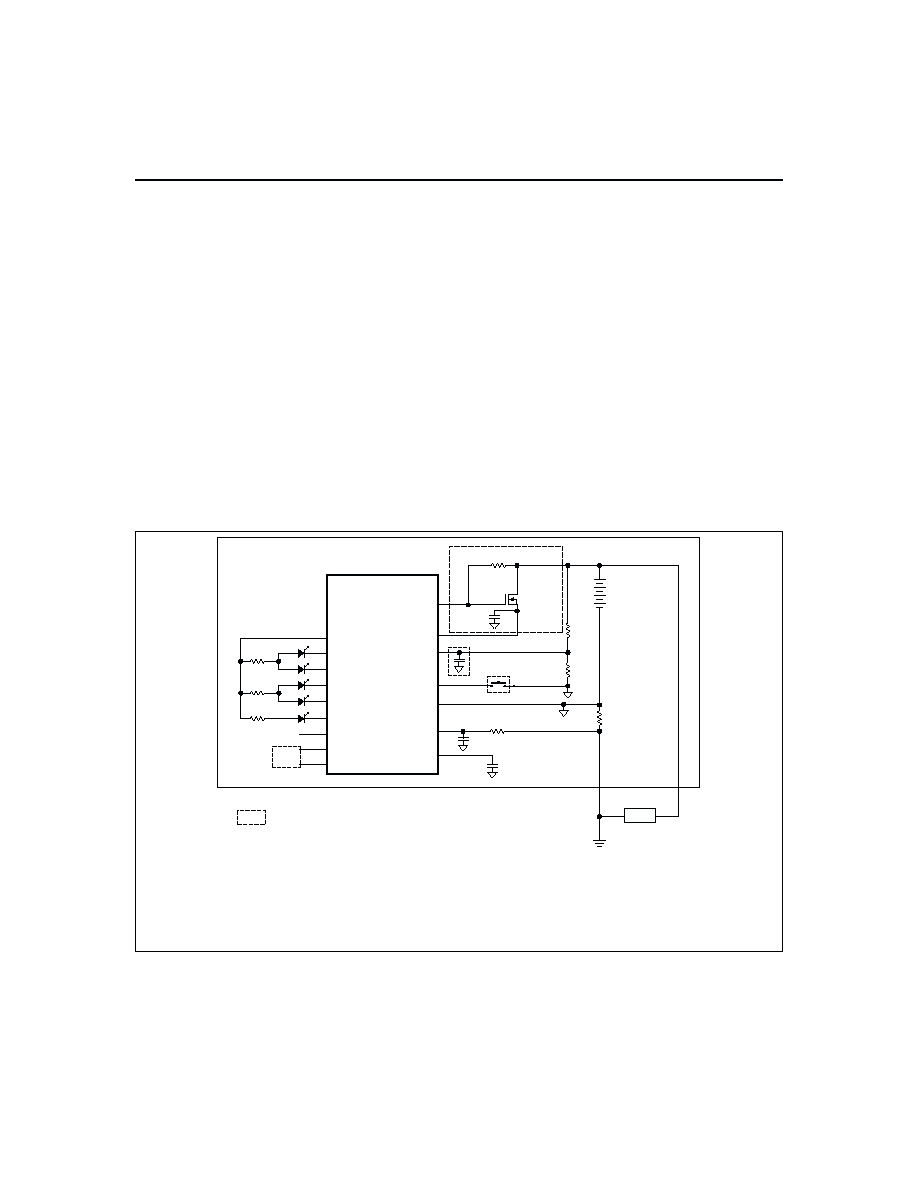
Figure 1 shows a typical battery pack application of the
b q 2 0 5 2 u s i n g t h e L E D d i s p l ay c a p a b i l i t y a s a
charge-state indicator.
The bq2052 displays capacity
with two, four, or five LEDs using the programmed full
count (PFC) as the battery's "full" reference. The bq2052
has a push-button input for momentarily enabling the
LED display.
Measurements
The bq2052 uses a voltage-to-frequency converter (VFC)
for discharge measurement and an analog-to-digital con-
verter (ADC) for battery voltage measurement.
Discharge Counting
The VFC measures the discharge flow of the battery by
monitoring a small value sense resistor between the SR
pin and V
SS
as shown in Figure 1. The bq2052 detects
"discharge" activity when the potential at the SR input,
V
SRO
, is positive. The bq2052 integrates the signal over
time using an internal counter. The fundamental rate of
the counter is 3.125
µVh. The VFC measures signals up
to 0.5V in magnitude.
Digital Magnitude Filter
The bq2052 has a digital filter to eliminate discharge
counting below a set threshold. The minimum discharge
threshold, V
SRD
, for the bq2052 is 250
µV.
3
Preliminary
bq2052
FG205201.eps
PROG6
CP
HDQ
SEG5
SEG4
SEG3
SEG2
SEG1
VSS
DISP
SB
VCC
REF
bq2052
Gas Gauge IC
LCOM
SR
RBI
0.1
µF
Q1
ZVNL110A
R1
C1
100K
RS
RB1
RB2
Load
Indicates optional.
2. V
CC
can connect directly to two lithium primary cells
(6.0V nominal and should not exceed 6.5V).
Otherwise, R1, C1, and Q1 are needed for regulation of > 2 cells.
3. Programming resistors and ESD-protection diodes are not shown.
4. R-C on SR is required.
To
µC
H or L
5. A series diode is required on RBI if the bottom series cell is used as the backup source.
If the cell is used, the backup capacitor is not required, and the anode is connected to the
positive terminal of the cell.
1.
Notes:
Figure 1. Application Diagram--5-Segment LED Display
Voltage Monitoring and Thresholds
In conjunction with monitoring the SR input for dis-
charge currents, the bq2052 monitors the battery poten-
tial through the SB pin. The voltage at the SB pin, V
SB
,
is developed through a high impedance resistor network
connect across the battery.
The bq2052 monitors the
voltage at the SB pin and reports the voltage in the VSB
register (address = 0bh).
T h e b q 2 0 5 2 c o m p a r e s t h e V
S B
r e a d i n g t o t w o
end-of-discharge voltage (EDV) thresholds.
The EDV
threshold levels are used to determine when the battery
has reached an "empty" state. The EDV thresholds for
the bq2052 are programmable with the default values
fixed at:
EDV1 (first) = 0.76V
EDVF (final) = EDV1 - 0.10V = 0.66V
If V
SB
is below either of the two EDV thresholds for 8
consecutive samples over a 4 second period, the bq2052
sets the associated flag in the FLGS1 register (address =
01h). Once set, the EDV flags remain set, independent
of V
SB
.
Temperature
The bq2052 has an internal temperature sensor to mea-
sure temperature. The bq2052 determines the tempera-
ture and stores it in the TEMP register (address = 02h).
The bq2052 uses temperature to adapt remaining capac-
ity for the battery's discharge efficiency.
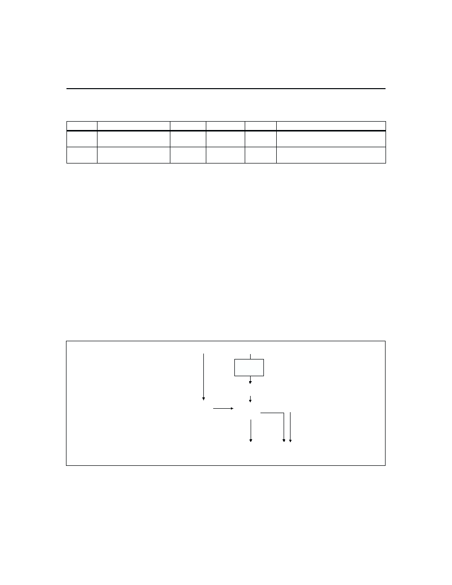
Gas Gauge Operation
General
The operational overview diagram in Figure 2 illus-
trates the operation of the bq2052. The bq2052 accumu-
lates a measure of discharge currents and calculates
available capacity. The bq2052 compensates available
capacity for discharge rate and temperature and pro-
vides the information in the Compensated Available Ca-
pacity (CAC) registers (address = 0eh0fh). The main
counter, Discharge Count Register (DCR) (address =
2eh), represents the cumulative amount of charge re-
moved from the battery. Battery discharging increments
the DCR register.
4
bq2052
Preliminary
FG2052.eps
Efficiency
Factor
Discharge
Current
Rate and
Temperature
Compensated
Available
Capacity
(CAC)
Complete
Data Set
Full Nominal
Available Charge
(FNAC)
Discharge
Count
Register
(DCR)
+
Inputs
Main Counters
Outputs
Chip-Controlled
Available Charge
LED Display
Serial Port
+
Figure 2. Operational Overview
Symbol
Parameter
Typical
Maximum
Units
Notes
INL
Integrated non-linearity
error
± 2
± 4
%
Add 0.1% per °C above or below 25°C
and 1% per volt above or below 4.25V.
INR
Integrated non-
repeatability error
± 1
± 2
%
Measurement repeatability given
similar operating conditions.
Table 1. bq2052 Current-Sensing Errors

Main Gas-Gauge Registers
Programmed Full Count
The PFC register stores the user-specified battery full
capacity. The 8-bit PFC registers stores the full capacity
in mVh scaled as shown in Table 2.
Full Nominal Available Capacity
The FNAC register stores the full capacity reference of
the battery. It can be programmed to initialize to PFC
or zero. The 8-bit FNAC register stores data scaled to
the same units as PFC. The bq2052 does not update
FNAC during the course of operation; therefore, if it is
programmed to 0 on initialization, it must be written to
full using the serial port.
Discharge Count Register
The DCR is the main gas gauging register and contains
the cumulative amount of discharge counted by the
bq2052.
The 16-bit register stores data scaled to the
same units as PFC.
Compensated Available Capacity
The CAC registers contain the current available capac-
ity of the battery.
The data stored in CAC represents
the amount of remaining capacity of the battery compen-
sated for rate and temperature use conditions. Tables 3,
4, and, 5 outline the options for typical efficiency com-
pensation factors for lithium primary batteries. The
bq2052 applies the efficiency factors to FNAC to derive
CAC.
The bq2052 applies the compensation according to the
formula:
CAC = [F
CE
FNAC] - DCR
Where F
CE
is the calculated efficiency compensation
factor, FNAC = Full Nominal Available Capacity and
DCR = Discharge Count Register.
The bq2052 calculates an F
CE
based on the battery dis-
charge rate and temperature. The discharge rate por-
tion of the F
CE
compensation is a "peak hold" function;
therefore, the bq2052 latches the highest discharge rate
it has measured and uses the highest rate to calculate
F
CE
throughout the complete discharge cycle.
The
highest discharge rate measured by the bq2052 is stored
in MRATE (address = 12h).
The bq2052 does not latch the temperature portion of an
F
CE
calculation.
Therefore, CAC may increase or de-
crease during the course of a complete discharge cycle if
a temperature shift causes a change in the calculated
F
CE
value.
Programming the bq2052
The bq2052 is programmed with the PROG
16
pins.
During power-up or initialization, the bq2052 reads the
state of these six three-level inputs and latches in the
programmable configuration settings.
5
Preliminary
bq2052
7
PROG
x
Programmed
Full Count
(PFC)
PROG
3
Units
1
2
H
Z
L
-
-
-
SCALE =
1/40
SCALE =
1/80
SCALE =
1/160
mVh/
count
H
H
48128
1203
602
301
mVh
H
Z
46080
1152
576
288
mVh
H
L
43264
1082
541
271
mVh
Z
H
39936
998
499
250
mVh
Z
Z
38400
960
480
240
mVh
Z
L
36096
902
451
226
mVh
L
H
31744
794
397
199
mVh
L
Z
28928
723
362
181
mVh
L
L
26112
653
327
164
mVh
Table 2. bq2052 Programmed Full Count mVh