 | ÐлекÑÑоннÑй компоненÑ: BQ2056SN | СкаÑаÑÑ:  PDF PDF  ZIP ZIP |
Äîêóìåíòàöèÿ è îïèñàíèÿ www.docs.chipfind.ru
1
Features
Ideal for single- and dual-cell Li-Ion
packs with coke or graphite anodes
Dropout voltage as low as 0.3V
AutoCompTM dynamic compensa-
tion of battery pack's internal im-
pedance
Optional temperature-monitoring
before and during charge
Integrated voltage and current
regulation with programmable
ch a r g e - c u r r e n t a n d h i g h - o r
low-side current sensing
Integrated cell conditioning for
reviving deeply discharged cells
and minimizing heat dissipation
during initial stage of charge
Better than ±1% voltage regula-
tion accuracy
Charge status output for LED or
host processor interface
Automatic battery-recharge feature
Charge termination by minimum
current
Low-power sleep mode
Packaging: 8-pin SOIC, 8-pin
TSSOP
General Description
The BENCHMARQ bq2057 series
advanced Li-Ion linear charge-man-
agement ICs are designed for
cost-sensitive and compact portable
electronics. They combine high-accu-
racy current and voltage regulation,
battery conditioning, temperature
monitoring, charge termination,
ch a r g e - s t a t u s i n d i c a t i o n , a n d
AutoComp charge-rate compen-
sation in a single 8-pin IC.
The bq2057 continuously measures
battery temperature using an exter-
nal thermistor. For safety reasons,
the bq2057 inhibits charge until the
b a t t e r y t e m p e r a t u r e i s w i t h i n
user-defined thresholds. The bq2057
then charges the battery in three
phases: conditioning, constant cur-
rent, and constant voltage. If the
b a t t e r y v o l t a g e i s b e l o w t h e
low-voltage threshold V
MIN
, the
bq2057 trickle-charges to condition
the battery. The conditioning charge
rate is set at 10% of the regulation
current. The conditioning current
also minimizes heat dissipation in
the external pass-element during
the initial stage of charge.
After conditioning, the bq2057 ap-
plies a constant current to the bat-
tery. An external sense-resistor sets
the magnitude of the current. The
sense-resistor can be on either the
low or the high side of the battery
without additional components. The
constant-current phase continues
u n t i l t h e b a t t e r y r e a c h e s t h e
charge-regulation voltage.
The bq2057 then begins the con-
stant-voltage phase. The accuracy of
the voltage regulation is better than
±1% over the operating-temperature
and supply-voltage ranges. For sin-
gle and dual cells with either coke
or graphite anodes, the bq2057 is of-
fered in four fixed-voltage versions:
4.1V, 4.2V, 8.2V, and 8.4V. Charge
stops when the current tapers to the
ch a r g e t e r m i n a t i o n t h r e s h o l d ,
V
TERM
. The bq2057 automatically
restarts the charge if the battery
voltage falls below the V
RCH
thresh-
old.
The designer also may use the
AutoComp feature to reduce charg-
ing time. This proprietary technique
allows safe and dynamic compensa-
tion for the internal impedance of
the battery pack during charge.
bq2057
Pin Connections
Advanced Li-Ion Linear Charge
Management IC
1
PN-205701.eps
8-Pin PDIP, Narrow SOIC, or TSSOP
2
3
4
8
7
6
5
SNS
BAT
V
CC
TS
COMP
CC
V
SS
STAT
Pin Names
SNS
Current-sense input
BAT
Battery-voltage input
V
CC
Supply voltage
TS
Temperature sense
input
STAT
Charge status output
V
SS
Ground input
CC
Charge control output
COMP
Charge-rate
compensation input
SLUS025A JANUARY 2000 - REVISED MAY 2000
Pin Descriptions
SNS
Current-sense input
Battery current is sensed via the voltage de-
veloped on this pin by an external sense re-
sistor.
BAT
Battery voltage input
Voltage sense-input tied directly to the posi-
tive side of the battery.
V
CC
V
CC
supply input
TS
Temperature sense input
Input for an external battery-temperature
monitoring circuit. Connecting this input to
Vcc/2 disables this feature.
STAT
Charge status output
Tri-state indication of charge-in-progress,
charge-complete, and temperature fault.
V
SS
Ground input
CC
Charge-control output
Source-follower output that drives an exter-
nal pass-transistor for current and voltage
regulation.
COMP
Charge-rate compensation input
Sets the charge-rate compensation level. The
voltage-regulation output may be pro-
grammed to vary as a function of the charge
current delivered to the battery.
2
bq2057
VCC
CC
CONTROL
BLOCK
V
REG
V
SS
V
CC
COMP
BAT
POWER
RESET
ON
SNS
2057FBD.eps
TS
V
TS1
, V
TS2
V
SNS
LED
STAT
STAT
K
COMP
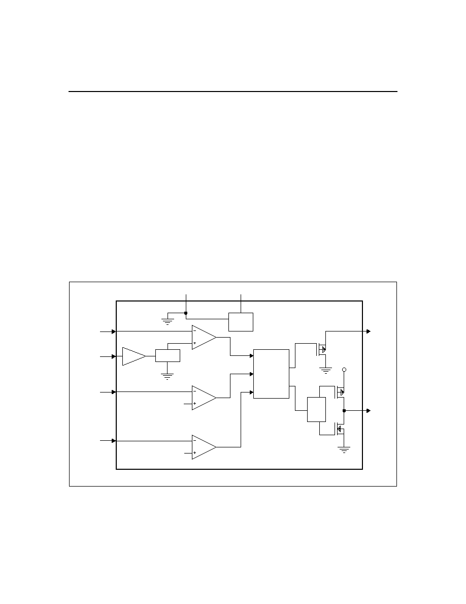
Figure 1. Functional Block Diagram
Functional Description
Figure 1 is a functional block diagram, Figure 2 an oper-
ational flow chart, and Figure 3 a typical charger sche-
matic for the bq2057.
Charge Qualification and Conditioning
When power is applied, the bq2057 starts a charge-cycle
if a battery is already present or when a battery is in-
serted. Charge qualification is based on battery temper-
ature and voltage. The bq2057 suspends charge if the
battery temperature is outside the V
TS1
to V
TS2
range
and suspends charge until the battery temperature is
within the allowed range. The bq2057 also checks the
battery voltage. If the battery voltage is below the
l o w - v o l t a g e t h r e s h o l d V
M I N
, t h e b q 2 0 5 7 u s e s
trickle-charge to condition the battery. The conditioning
charge rate I
COND
is set at 10% of the regulation cur-
rent. The conditioning current also minimizes heat dis-
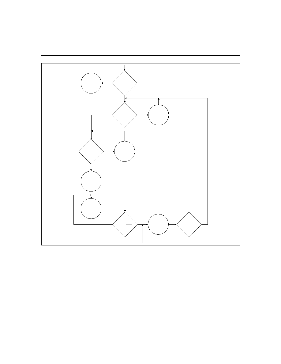
3
bq2057
V
CC
> V
BAT
Temperature
Check
TS > V
TS1
TS < V
TS2
V
BAT
V
MIN
I
BAT
V
BAT
V
RCH
Sleep Mode
LED = Hi-Z
NO
YES
YES
NO
NO
NO
2057OFC.eps
NO
YES
YES
YES
Current
Regulation
Phase
LED = High
Voltage
Regulation
Phase
LED = HIGH
Charge
Complete
LED = LOW
Temperature
Fault
LED = Hi-Z
Conditioning
Phase
LED = High
I
REG
10
Figure 2. bq2057 Operational Flow Chart
sipation in the external pass-element during the initial
stage of charge. See Figure 4 for a typical charge-algo-
rithm.
Current Regulation
The bq2057 regulates current while the battery-pack
voltage is less than the regulation voltage, V
REG
. The
bq2057 monitors charge current at the SNS input by the
voltage drop across a sense-resistor, R
SNS
, in series with
the battery pack. In high-side current sensing configura-
tion (Figure 5), R
SNS
is placed between the Vcc and SNS
pins, and in low-side sensing (Figure 6) the R
SNS
is
placed between Vss (battery negative) and SNS (charger
ground) pins.
Charge-current feedback, applied through pin SNS, main-
tains regulation around a threshold of V
SNS
. The follow-
ing formula calculates the value of the sense resistor:
R
SNS
=
V
I
SNS
REG
where I
REG
is the desired charging current.
Voltage Monitoring and Regulation
Voltage regulation feedback is through pin BAT. This in-
put is tied directly to the positive side of the battery
pack. The bq2057 monitors the battery-pack voltage be-
tween the BAT and V
SS
pins. The bq2057 is offered in
four fixed-voltage versions for single- and dual-cells with
either coke or graphite anodes: 4.1V, 4.2V, 8.2V, and
8.4V.
Other regulation voltages can be achieved by adding a
voltage divider between the positive and negative termi-
nals of the battery pack. The voltage divider presents a
scaled battery pack voltage to BAT input. (See Figures 7
and 8.) The resistor values R
B1
and R
B2
for the voltage
divider are calculated by the following equation:
R
R
N
V
V
B1
B2
CELL
REG
=
- 1
where
N = Number of cells in series
V
CELL
= Desired regulation voltage per cell
Charge Termination and Re-Charge
The bq2057 monitors the charging current during the
voltage-regulation phase. The bq2057 declares a "battery-
complete" condition and terminates charge when the
current tapers off to the charge termination threshold,
V
TERM
. A new charge cycle begins when the battery volt-
age falls below the
VRCH
threshold.
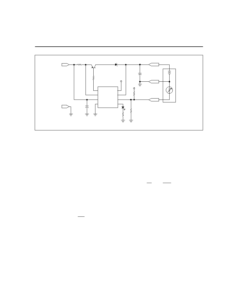
4
bq2057
2057ldc.eps
PACK+
Q1
FZT788B
D2
bq2057
CC
Battery
Pack
V
CC
V
CC
R
T1
R
T2
NTC
C1
0.1
µF
C2
0.1
µF
R2
2k
R
SNS
0.2
R1
1k
D1
SNS
VCC
VSS
COMP
BAT
TS
STAT
DC+
DC-
TEMP
PACK-
7
8
2
4
5
1
3
6
Figure 3. Low-Dropout Single- or Dual-Cell Li-Ion Charger
*
* Optional.
5
bq2057
BAT+
BAT-
DC+
DC-
R
SNS
STAT
5
V
SS
6
CC
7
COMP
8
SNS
1
BAT
2
V
CC
3
TS
4
bq2057
2057HSCS.eps
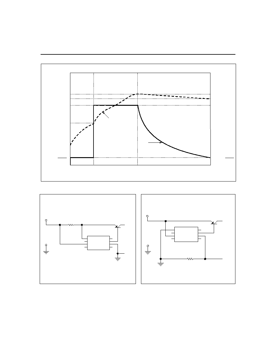
Figure 5. High-Side Current Sensing
GR2057b.eps
V
BAT
I
BAT
V
PACK
V
REG
V
MIN
I
REG
Low-Current
Conditioning
Phase
Current
Regulation
Phase
Voltage Regulation Phase
(Shown with the optional AutoComp feature)
I
REG
10
I
REG
10
I
COND
=
I
FULL
=
Figure 4. bq2057 Typical Charge Algorithm
STAT
5
V
SS
6
CC 7
COMP 8
SNS
1
BAT
2
V
CC
3
TS
4
bq2057
BAT+
BAT-
DC+
R
SNS
2057LSCS1.eps
DC-
Figure 6. Low-Side Current Sensing