Features
ä Complete bq2011 Gas Gauge solution for NiCd
packs in high discharge rate applications
ä Five surface-mounted LEDs to display
state-of-charge information
ä Battery state-of-charge monitoring for 4- to 12-cell
series applications
ä On-board regulator allows direct connection to the
battery
ä Battery information available over a single-wire
bidirectional serial port
ä Nominal capacity pre-configured
ä Compact size for battery pack integration
General Description
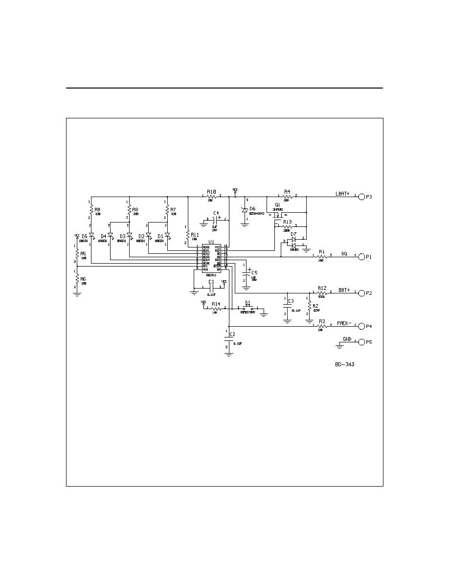
The bq2111L Gas Gauge Module provides a complete
and compact solution for capacity monitoring of NiCd
battery packs in high discharge rate applications such
as power tools. Designed for battery pack integration,
the bq2111L incorporates a bq2011 Gas Gauge IC, five
surface-mounted LEDs, and the other discrete compo-
nents necessary to monitor and display accurately the
capacity of 4
- to 12 -series cells. The only external compo-
nent required is a low-value sense resistor connected be-
tween GND and PACK-. Contacts are also provided on
the bq2111L for direct connection to the battery stack
and the serial communications port (DQ). The battery
stack should be connected between BAT+ and GND.
Please refer to the bq2011 data sheet for the specifics on
the operation of the Gas Gauge.
Unitrode configures the bq2111L based on the informa-
tion requested in Table 1. The configuration defines the
number of series cells and the nominal battery pack ca-
pacity. The bq211L module uses the absolute LED dis-
play to indicate battery capacity.
In this mode, the
remaining capacity is represented as a percentage of the
programmed capacity.
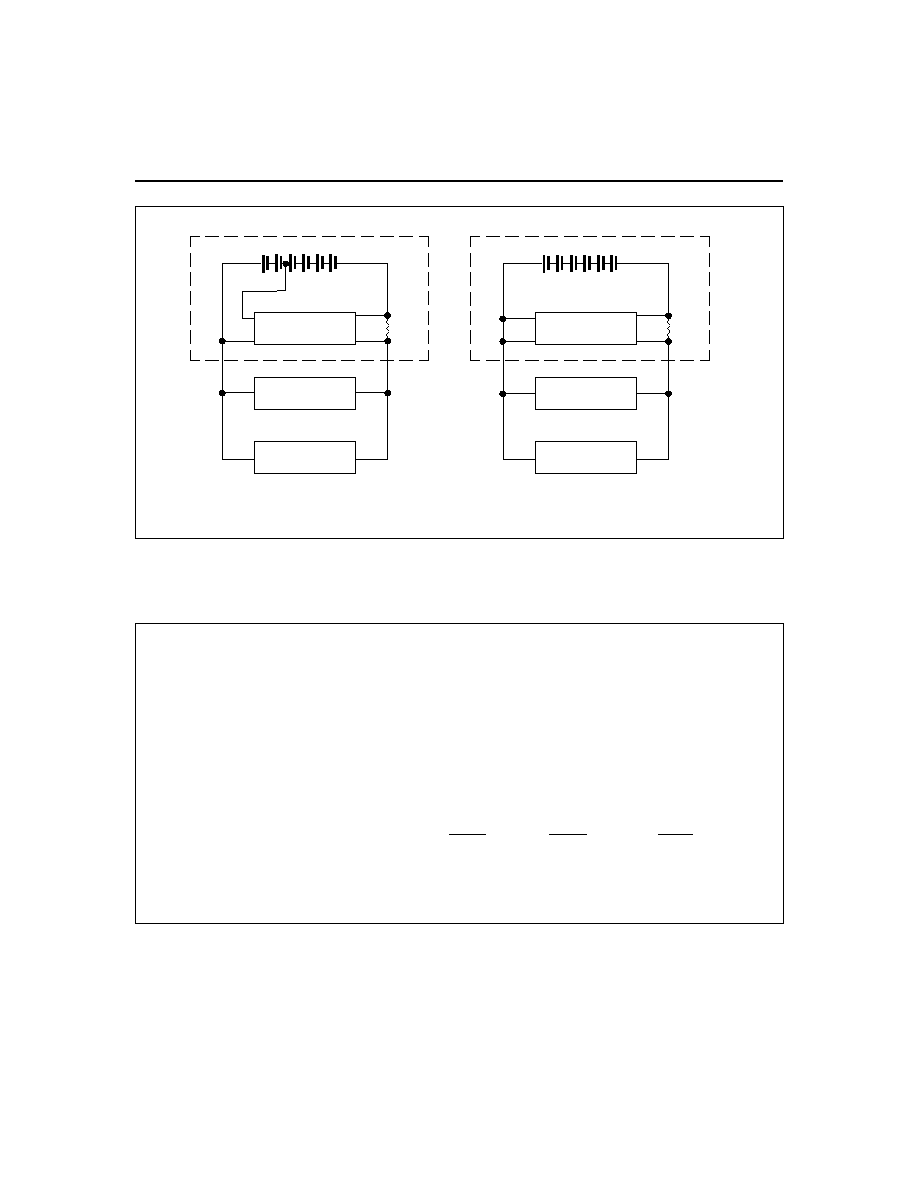
The bq2111L can operate directly from four series cells
within the pack using the LBAT+ supply input. For four
series cell applications or applications using the on-
board regulator, LBAT+ should be connected to BAT+.
Please refer to Figure 1 for module connection illustra-
tions.
A module development kit is also available for the
bq2111L.
The bq2111LB-KT includes one configured
module and the following:
1)
An interface board that allows connection to the se-
rial port of an AT-compatible computer.
2)
Menu-driven software with the bq2111L to display
charge/discharge activity and to allow user inter-
face to the bq2011 from any standard DOS PC.
3)
Source code for the TSR.
Pin Descriptions
P1
DQ/Serial communication port
P2
BAT+/Battery positive/Pack positive
P3
LBAT+/Four--cell power
P4
PACK-/Pack negative
P5
GND/Ground
1
NiCd Gas Gauge Module with LEDs
for High Discharge Rates
bq2111L
7/96
2
bq2111L
Customer Name: ___________________________________________________________________________
Contact: _________________________________________
Phone: ______________________________
Address: _________________________________________________________________________________
_________________________________________________________________________________
Sales Contact: ____________________________________
Phone: ______________________________
Number of series battery cells (412)
________________________________________
Sense resistor size in m
1
________________________________________
Battery pack capacity (mAh)
________________________________________
Discharge rate(A)
Min.
Avg.
Max.
Charge rate (A)
________________________________________
FAE approval: _____________________________________
Date:________________________________
Table 1. bq2111L Module Configuration
Note:
1.
Sense resistor is not included with board.
FG-130
Charger
Load
bq2111L
Cells
Battery Pack
P5
P4
Sense
Resistor
P3
P2
PACK+
PACK-
(b) Regulated Supply
(a) 4-Cell Supply
Charger
Load
PACK+
P2
P3
Battery Pack
P4
bq2111L
P5
Resistor
PACK-
Sense
Cells
Figure 1. Module Connection Diagram

5
Absolute Maximum Ratings
Symbol
Parameter
Minimum
Maximum
Unit
Notes
V
CC
Relative to V
SS
-0.3
+7.0
V
bq2011
All other pins
Relative to V
SS
-0.3
+7.0
V
bq2011
T
OPR
Operating temperature
0
+70
°C
Commercial
T
STR
Storage temperature
-40
+85
°C
Note:
Permanent device damage may occur if Absolute Maximum Ratings are exceeded. Functional opera-
tion should be limited to the Recommended DC Operating Conditions detailed in this data sheet. Expo-
sure to conditions beyond the operational limits for extended periods of time may affect device reliability.
DC Electrical Characteristics
(TA = TOPR)
Symbol
Parameter
Minimum
Typical
Maximum
Unit
Conditions/Notes
NumCell
Number of series cells in
battery pack
4
-
12
-
BAT+
Positive terminal of pack
GND
NumCell
1.2V
*
NumCell
1.8V
*
V
V
SR
Voltage across the sense re-
sistor, P4 to P5
-0.3
-
2
V
V
CC
Supply voltage (direct cell
operation)
LBAT+
3.0
4.8
7.2
V
I
CC
Supply current at BAT+
terminal (no external
loads)
-
120
250
µA
R
DQ
Internal pull-down
500k
-
-
1
I
OL
Open-drain sink current
DQ
-
-
5.0
mA
1
V
OL
Open-drain output low, DQ
-
-
0.5
V
1
I
OL
< 5mA
V
IHDQ
DQ input high
2.5
-
-
V
1
V
ILDQ
DQ input low
-
-
0.8
V
1
V
OS
Voltage offset
150
µV
1
bq2111L
Note:
1.
Characterized on PCB, IC 100% tested.