Power_Minder_?_Mini-Board
Features
ä Complete and compact charge/discharge counter
ä Combines the bq2018, voltage regulator, sense
resistor, and backup capacitor on a single PCB
ä Communicates charge/discharge information to a
host with a single-wire interface
ä Designed for battery pack integration
Less than 0.5 square inches
Small size allows it to fit in the crevice formed
by two adjacent cells
Low operating current
ä Direct connections for the pack cells and
communications port
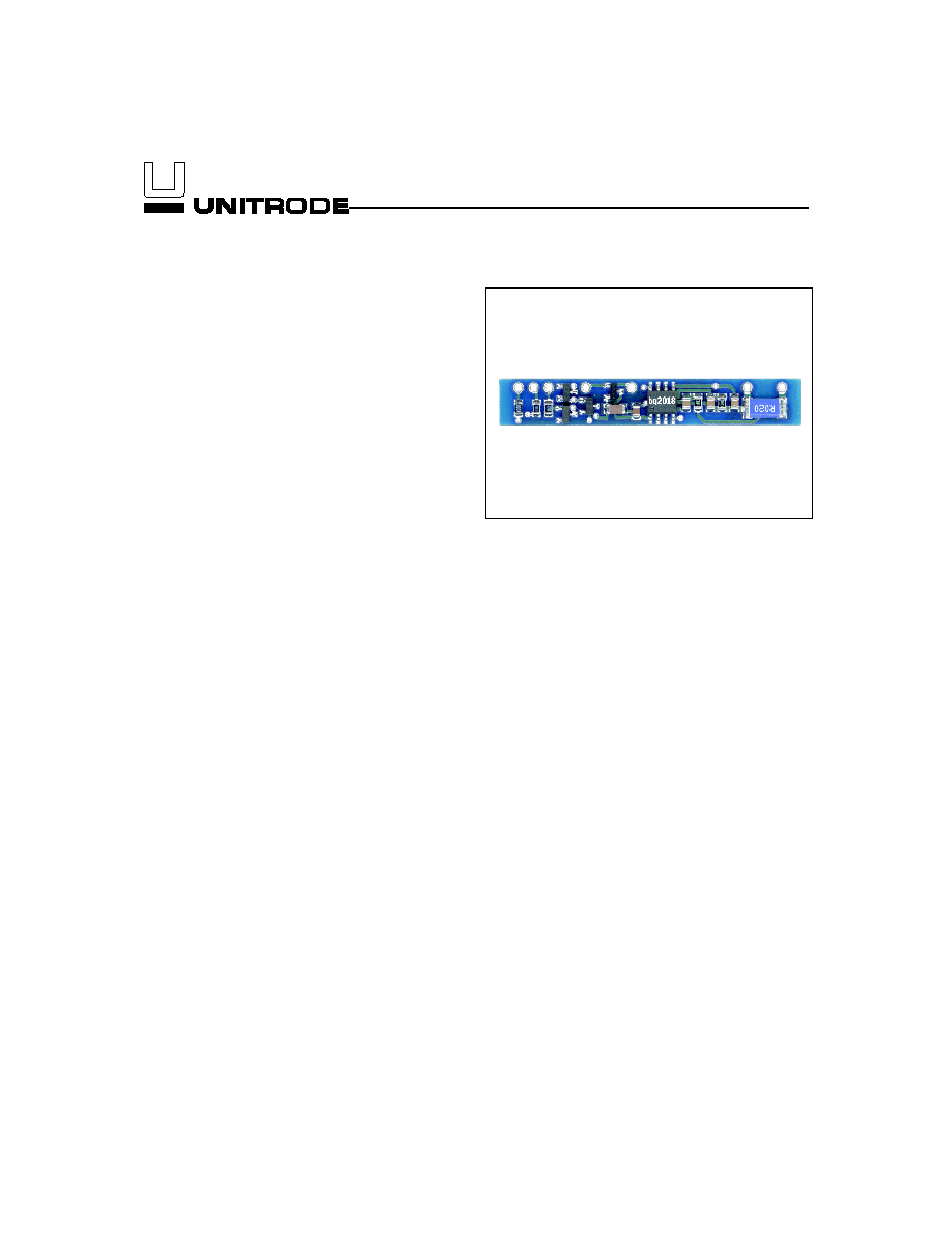
General Description
The bq2118 Power Minder mini-board provides a com-
plete and compact solution for charge and discharge
counting of all types of battery chemistries, including
NiCd, NiMH, or Li-Ion batteries. Designed for battery
pack integration,
the bq2118 incorporates a bq2018
Power Minder IC, supply voltage regulator, sense resistor,
and backup capacitor on a small circuit board. The mod-
ule provides direct connections for the positive and nega-
tive terminals of the series cells in the battery pack, and
can fit in the crevice formed by two adjacent cells. The
bq2118 allows a battery pack to be equipped easily with
accurate charge/discharge counting electronics.
Unitrode configures the bq2118 based on the informa-
tion requested in Table 1. The configuration defines the
battery chemistry, the number of series cells, and the
charge/discharge current. Figure 1 shows how the mod-
ule connects to the cells.
A module development kit is also available for the
bq2118. The bq2118B-KT includes one configured mod-
ule and the following:
1.
An EV2200-18 interface board that allows connec-
tion to the serial port of an AT-compatible com-
puter.
2.
Menu-driven software to display charge/discharge
activity and to allow user interface to the bq2118
from any standard Windows 3.1 or 95 PC.
Pin Descriptions
BAT+
Battery positive/pack positive
BAT-
Battery negative
HDQ
Communications port
PACK-
Pack negative
WAKE
Wakeup output
RBI
Register backup input
V
CC
bq2018 supply voltage
1
Power MinderTM Mini-Board
Preliminary
bq2118
5/99
2
bq2118
Preliminary
Customer Name: ___________________________________________________________________________
Contact: _________________________________________
Phone: ______________________________
Address: _________________________________________________________________________________
_________________________________________________________________________________
Sales Contact: ____________________________________
Phone: ______________________________
Number of series battery cells
____________________
Coke or graphite cell anode
____________________
Battery pack capacity (mAh)
____________________
Discharge rate into load (4.0A max)
Min. ________ Avg. _________ Max. _________
Charge rate (4.0A max)
____________________
FAE Approval: _____________________________________
Date:________________________________
Table 1. bq2118 Module Configuration
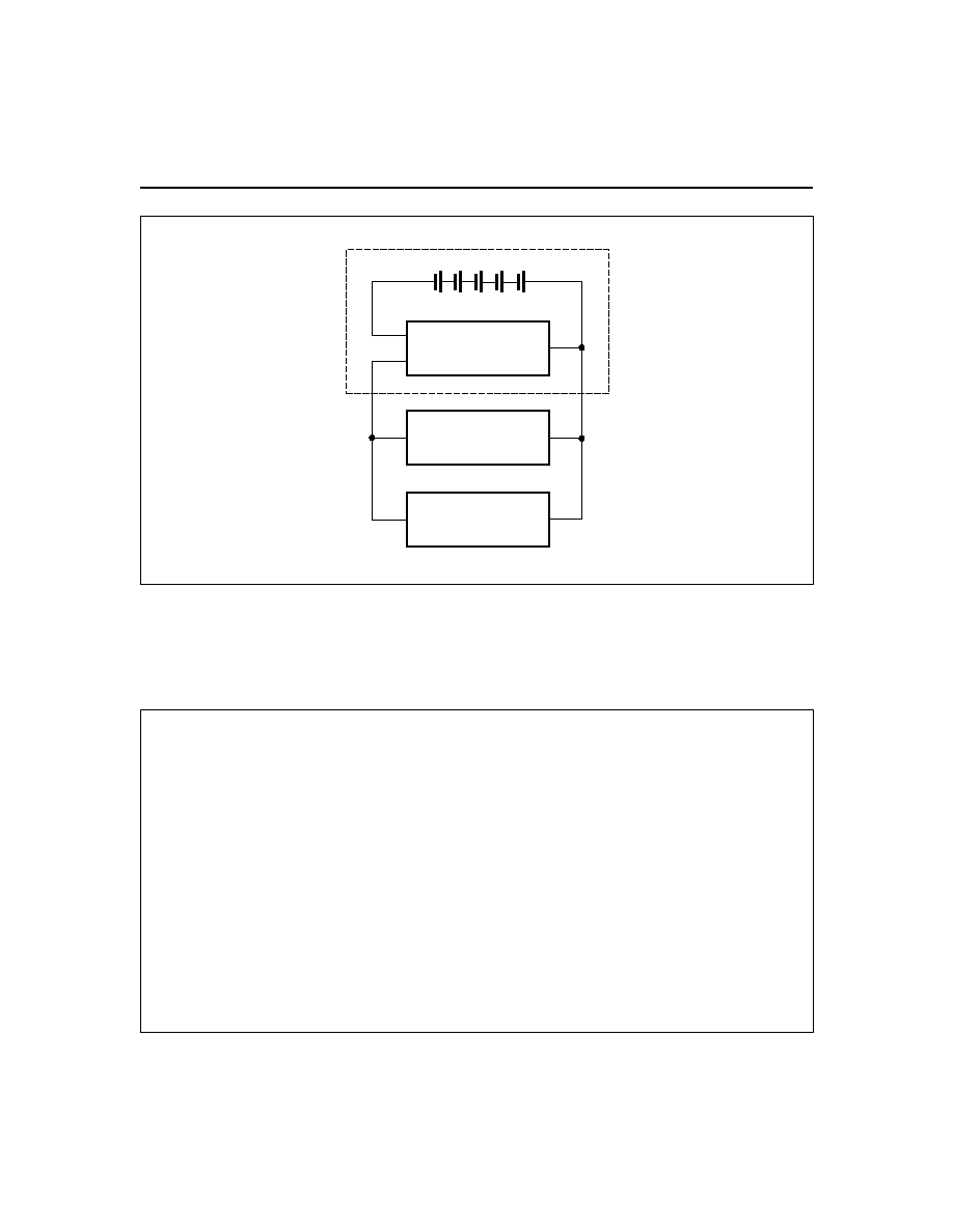
FG2118MCD.eps
Battery Pack
BAT-
PACK-
BAT+
bq2118
Load
Charger
Cells
PACK+
PACK-
Figure 1. Module Connection Diagram
3
RBI
SR2
SR1
WAKE
HDQ
VSS
VCC
REG
BQ2018
U1
1
2
3
4
5
6
7
8
C1
VCC
SST113
Q1
BAT+
BZX84C5V6
D1
2
HDQ
BZX84C5V6
D2
2
100
R5
C4
C2
C3
BAV99
D3
100K
d
s
R4
RBI
PACK-
BAT-
1W
0.05
R1
100K
R3
100K
R2
WAKE
1K
R6
VCC
0.01
µF
0.1
µF
0.1
µF
0.1
µF
0.1
µF
C5
2018typAp.eps
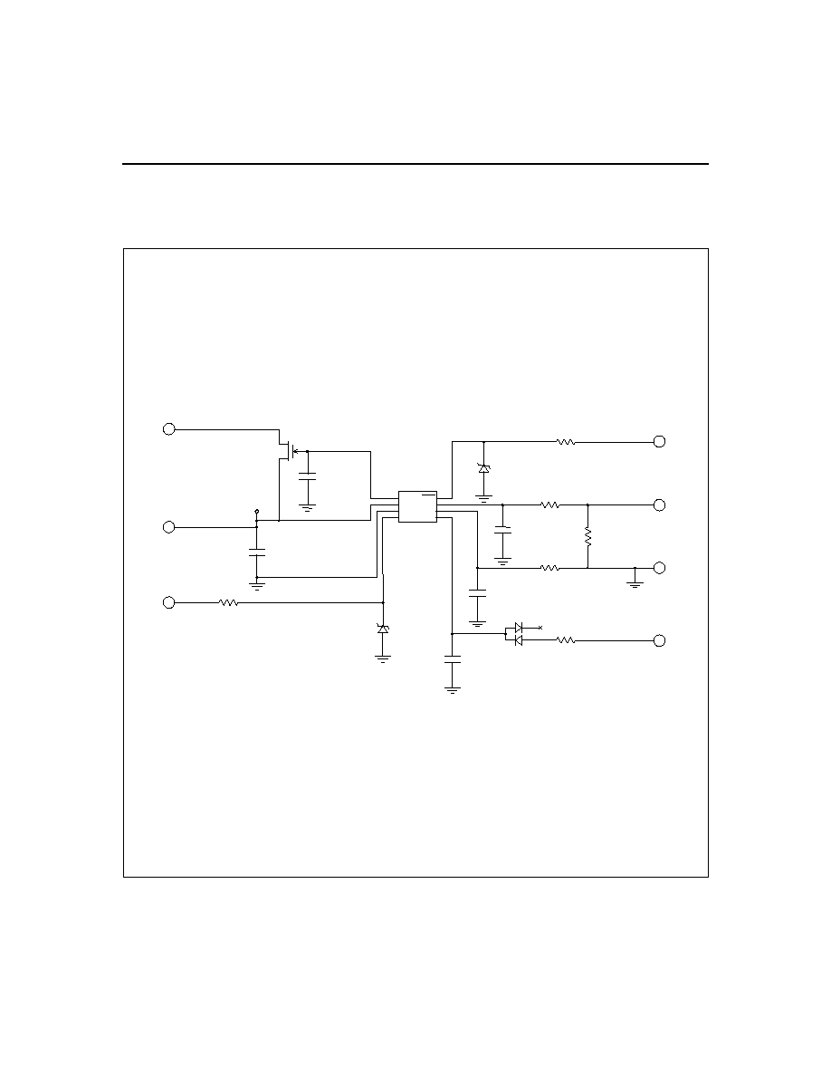
bq2118 Schematic
Preliminary
bq2118
4
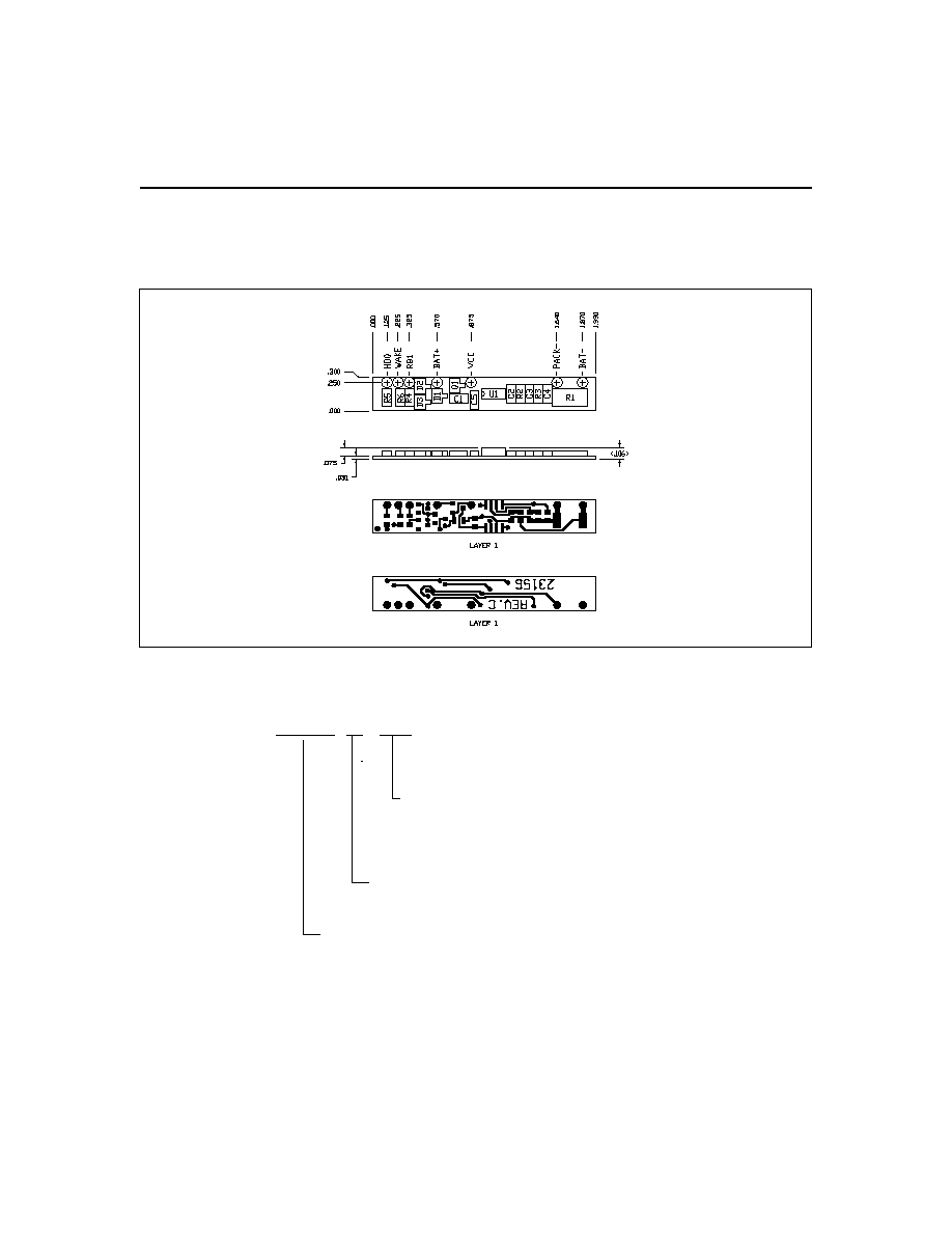
bq2118 Board
bq2118
Preliminary
bq2118
B XXX
Package Option:
B = Board-level product
Device:
Power Minder Mini-Board
Customer Code:
Blank = Sample or Pre-production
1
KT = Evaluation system
XXX = Customer-specific; assigned by Unitrode
2
Ordering Information
Notes:
1.
Requires configuration sheet (see Table 1)
2.
Example production part number: bq2118B-001

IMPORTANT NOTICE
Texas Instruments and its subsidiaries (TI) reserve the right to make changes to their products or to discontinue
any product or service without notice, and advise customers to obtain the latest version of relevant information
to verify, before placing orders, that information being relied on is current and complete. All products are sold
subject to the terms and conditions of sale supplied at the time of order acknowledgement, including those
pertaining to warranty, patent infringement, and limitation of liability.
TI warrants performance of its semiconductor products to the specifications applicable at the time of sale in
accordance with TI's standard warranty. Testing and other quality control techniques are utilized to the extent
TI deems necessary to support this warranty. Specific testing of all parameters of each device is not necessarily
performed, except those mandated by government requirements.
CERTAIN APPLICATIONS USING SEMICONDUCTOR PRODUCTS MAY INVOLVE POTENTIAL RISKS OF
DEATH, PERSONAL INJURY, OR SEVERE PROPERTY OR ENVIRONMENTAL DAMAGE ("CRITICAL
APPLICATIONS"). TI SEMICONDUCTOR PRODUCTS ARE NOT DESIGNED, AUTHORIZED, OR
WARRANTED TO BE SUITABLE FOR USE IN LIFE-SUPPORT DEVICES OR SYSTEMS OR OTHER
CRITICAL APPLICATIONS. INCLUSION OF TI PRODUCTS IN SUCH APPLICATIONS IS UNDERSTOOD TO
BE FULLY AT THE CUSTOMER'S RISK.
In order to minimize risks associated with the customer's applications, adequate design and operating
safeguards must be provided by the customer to minimize inherent or procedural hazards.
TI assumes no liability for applications assistance or customer product design. TI does not warrant or represent
that any license, either express or implied, is granted under any patent right, copyright, mask work right, or other
intellectual property right of TI covering or relating to any combination, machine, or process in which such
semiconductor products or services might be or are used. TI's publication of information regarding any third
party's products or services does not constitute TI's approval, warranty or endorsement thereof.
Copyright
©
1999, Texas Instruments Incorporated