Features
ä Complete smart battery solution for NiCd, NiMH,
and Li-Ion battery packs
ä Based on the bq2945 Gas Gauge IC
ä Accurate measurement of available battery
capacity
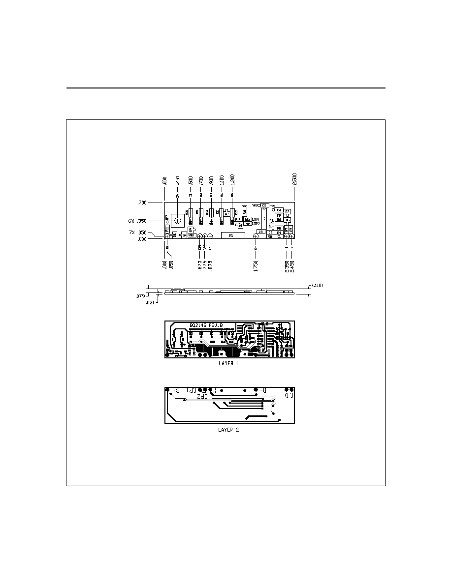
ä Designed for battery pack integration:
Measures only 2.5 (L) x 0.7 (W) inches
I n cl u d e s G a s G a u g e I C, c o n f i g u r a t i o n
EEPROM, and sense resistor
Five onboard state-of-charge LEDs with
push-button activation
Low operating current for minimal battery
drain
ä Critical battery information available over two-wire
serial port
General Description
The bq2145 Smart Battery Module provides a complete
solution for the design of intelligent battery packs. The
bq2145 uses the SMBus protocol and supports Smart
Battery Data commands in the SMB/SBD specifications.
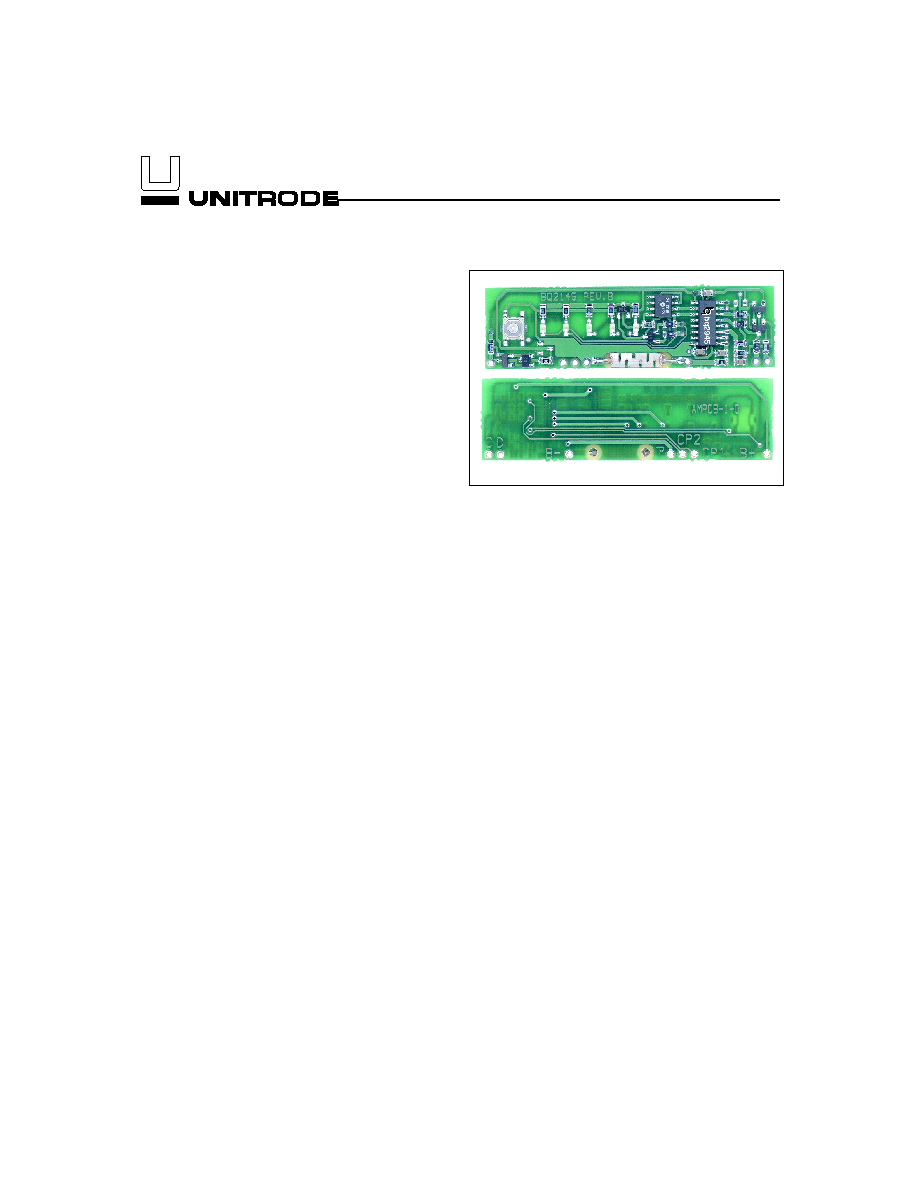
Designed for battery pack integration, the bq2145 com-
bines the bq2945 Gas Gauge IC with a serial EEPROM
on a small printed circuit board. The board includes all
the necessary components to accurately monitor battery
capacity and communicate critical battery parameters to
the host system or battery charger. The bq2145 also in-
cludes five LEDs. The push-button switch activates the
LEDs to show remaining battery capacity in 20% incre-
ments.
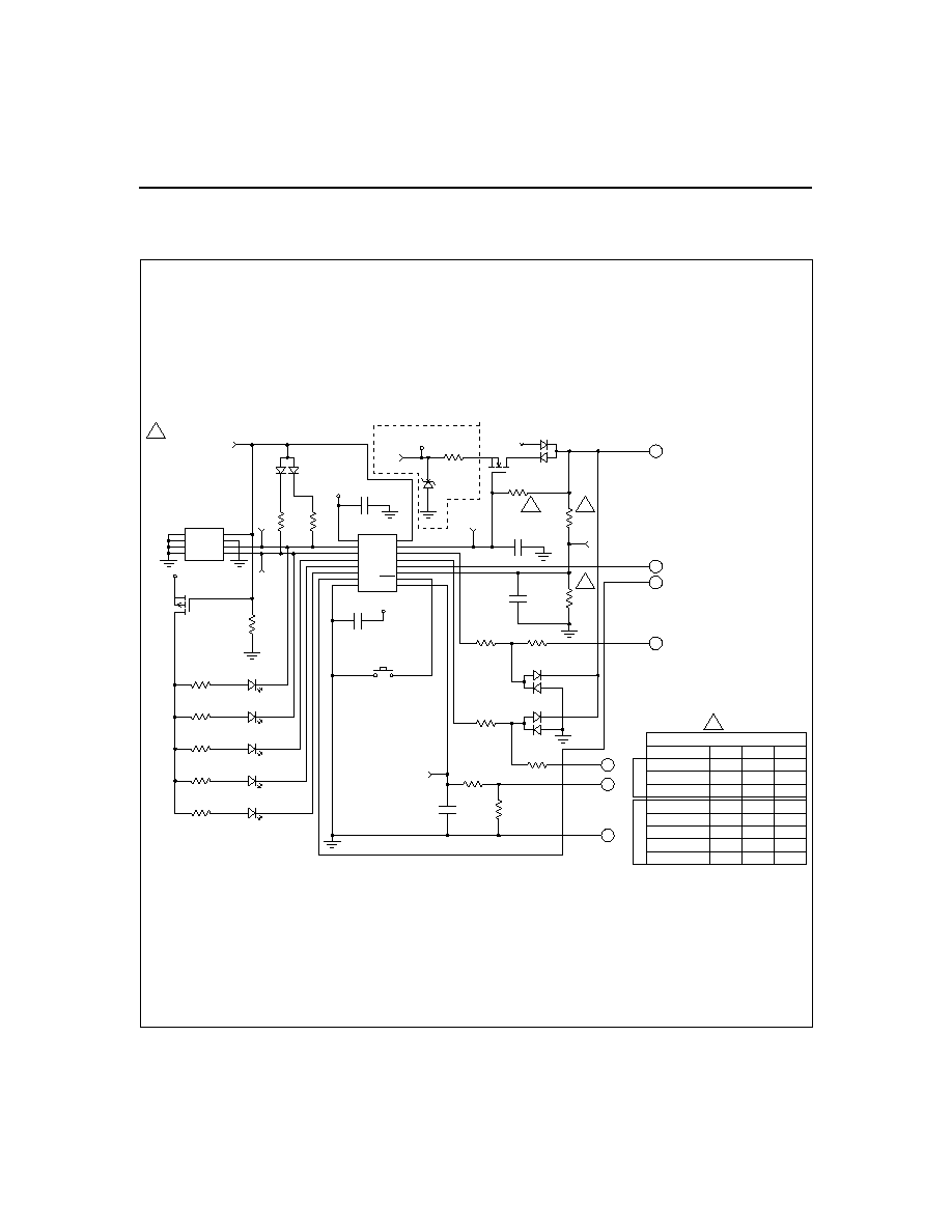
Contacts are provided on the bq2145 for direct connec-
tion to the battery stack (B+, B-) and the two-wire inter-
face (C, D). Please refer to the bq2945 data sheet for
specific information on the operation of the Gas Gauge
and communication interface.
Unitrode configures the bq2145 based on the informa-
tion requested in Table 1. The configuration defines the
pack voltage, capacity, and chemistry and charge control
parameters.
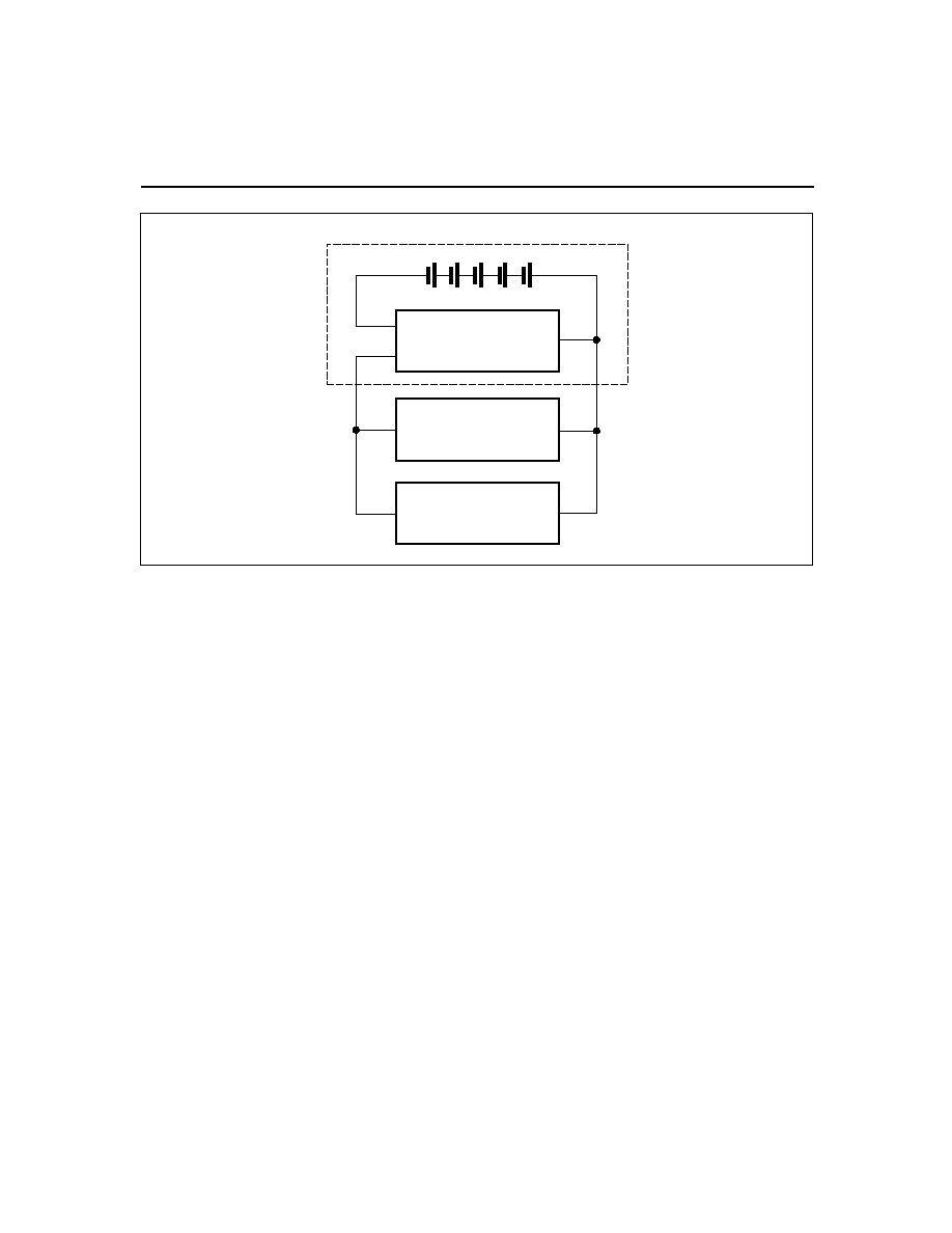
The Smart Battery Module uses the on-
board sense resistor to track charge and discharge activ-
ity of the battery pack. Figure 1 shows how the module
connects to the cells.
A module development kit is also available for the
bq2145. The bq2145B-KT or the bq2145LB-KT includes
one configured module and the following:
1)
An EV2200-45 interface board that allows connec-
tion to the serial port of any AT-compatible com-
puter.
2)
Menu-driven software to display charge/discharge
activity and to allow user interface to the Gas
Gauge IC and serial E
2
PROM from any standard
Windows 95 or 3.1x PC.
Pin Descriptions
B+
BAT+/Battery positive/Pack positive
P-
PACK-/Pack negative
C
SMBC/Communications clock
D
SMBD/Serial data
B-
BAT-/Battery negative
CP2
Control pin 2
CP1
Control pin 1
1
Smart Battery Module with LEDs
Preliminary
bq2145
5/99

3
Customer Name: ______________________________________________________________________________________________
Contact: _______________________________________________________
Phone:____________________________
Address:________________________________________________________________________________________________
Sales Contact: __________________________________________________
Phone: ____________________________
Board Configuration
LEDs and switch
________________
Yes or No
Display mode
________________
Relative or Absolute
Discharge rate (3.0A max.)
Min ____________
Avg ____________
Max ___________
Duration at max. discharge
________________
Number of series cells
________________
EEPROM Configuration
Typical Values
NiMH
Li-Ion
Remaining time alarm (min) _______________
Sets the low time alarm level
10 min
10 min
Remaining capacity alarm
(mAh)
_______________
Sets the low capacity alarm level
C/10
C/10
Charging voltage (mV)
_______________
Sets the requested charging voltage
65535
4.1V/cell
Design cpaacity (mAh)
_______________
Defines the battery pack capacity
3000
3600
Design voltage (mV)
_______________
Defines the battery pack voltage
12000
10800
Manufacturer date
_______________
Battery pack manufacturer date
mm/dd/yy mm/dd/yy
Serial number
_______________
Battery pack serial number
0-65535
0-65535
Fast-charging current (mA)
_______________
Sets the requested charging current
1C
1C
Maintenance charging
current (mA)
_______________
Sets the requested maintenance charging
current
C/20
0
Li-Ion taper current (mA)
_______________
Sets the upper limit for charge termination
NA
C/10
Maximum overcharge (mAh) _______________
Sets the maximum amount of overcharge
256mAh
128mAh
Maximum temperature (
°C) _______________ Sets the maximum charge temperature
61
°C
61
°C
T/t (°C/min)
_______________
Sets the termination rate
3°C/3min
4.6°C/20s
Fast-charge efficiency (%)
_______________
Sets the fast-charge efficiency factor
95%
100%
Maintenance charge effi-
ciency (%)
_______________
Sets the maintence charge efficiency factor
80%
100%
Self-discharge rate (%/day)
_______________
Sets the batterys self-discharge rate
1.5%/day
0.2%/day
EDV1 (mV)
_______________
Sets the initial end-of-discharge warning
1.05V/cell
3.0V/cell
EDVF (mV)
_______________
Sets the final end-of-discharge warning
1.0V/cell
2.8V/cell
Hold-off timer for
T/t (sec.) _______________ Sets the hold off period for T/t
termination
180s
320s
Manufacturer name
_______________
Programs manufacturer's name (11 char.
max)
bq
bq
Device name
_______________
Programs device name (7 char. max)
bq36
bq202
Chemistry
_______________
Programs pack's chemistry (7 char. max)
NiMH
LION
Manufacturer data
_______________
Open field (5 char. max)
2040
2040
FAE Approval
____________________________________
Date: ____________
Table 1. bq2145 Module Configuration
Preliminary
bq2145