 | ÐлекÑÑоннÑй компоненÑ: BQ2150H | СкаÑаÑÑ:  PDF PDF  ZIP ZIP |
Äîêóìåíòàöèÿ è îïèñàíèÿ www.docs.chipfind.ru
Features
ä Complete bq2050H Power Gauge solution for Li-Ion
battery packs
ä Battery information available over a single-wire
(HDQ) bidirectional serial port
ä Control signals to enhance pack protection
ä Battery state-of-charge monitoring for 2- to 5-cell
series applications
ä On-board regulator allows direct connection to the
battery
ä "L" version includes push-button activated LEDs to
display state-of-charge information
ä Nominal capacity pre-configured
ä Compact size for battery pack integration
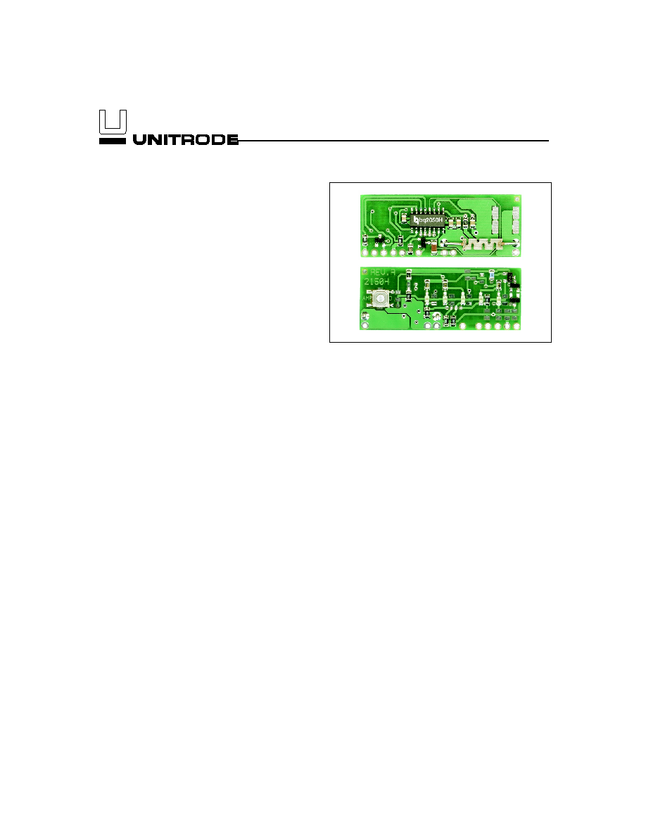
General Description
The bq2150H Power Gauge Module provides a complete
and compact solution for capacity monitoring of Li-Ion bat-
tery packs. Designed for battery pack integration, the
bq2150 incorporates a bq2150H Gas Gauge IC, a current
sense resistor, and all other components necessary to accu-
rately monitor and display the capacity of 2 to 5 series
cells.
The bq2150L includes five LEDs to display remaining ca-
pacity in 20% increments of the learned capacity.
The
LEDs are activated with the onboard push-button switch.
Contacts are provided on the bq2150H for direct connec-
tion to the battery stack (BAT+, BAT-) and the serial
communications port (HDQ). The RBI input provides
backup power to the bq2150H in the event that the cells
are removed or the battery is turned off. The bq2150H
has a 1
µF capacitor onboard connected to RBI to supply
backup power for about an hour. In battery packs that
use high-side FETs to control the charge/discharge of
the Li-Ion cells, the RBI input can be wired to a single
cell to provide prolonged data retention times. The SD
input allows an external signal (active low) to turn the
bq2050H IC off to minimize internal current consump-
tion of the battery pack and maximize storage life of the
pack in the system. When turned off, the bq2150H is
non-functional, and the RBI power source maintains
register information. Please refer to the bq2050H data
sheet for the specifics on the operation of the Gas Gauge.
Unitrode configures the bq2150H based on the informa-
tion requested in Table 1. The configuration defines the
number of series cells, the nominal battery pack capac-
ity, and the Li-Ion battery type (coke or graphite anode).
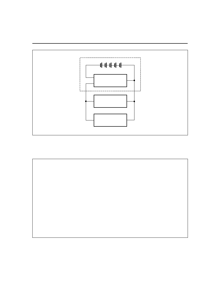
Figure 1 shows how the module connects to the cells.
A module development kit is also available for the
bq2150. The bq2150HB-KT or the bq2150HLB-KT in-
cludes one configured module and the following:
1)
An EV2200-50H interface board that allows con-
nection to the serial port of an AT-compatible com-
puter.
2)
Menu-driven software to display charge/discharge
activity and to allow user interface to the bq2150H
from any standard Windows 3.1x or 95 PC.
Pin Descriptions
P1
HDQ/Serial Communications port
P2
PSTAT/Protector status input
P3
BAT+/Battery positive/pack positive
P4
SD/Shutdown
P5
RBI/Register backup input
P6
GND/Ground
P7
PACK-/Pack negative
P8
BAT-/Battery negative
P9
CFC/Charge FET control output
1
Li-Ion Power GaugeTM Module
Preliminary
bq2150H
10/97
2
bq2150H
Preliminary
Customer Name: ___________________________________________________________________________
Contact: _________________________________________
Phone: ______________________________
Address: _________________________________________________________________________________
_________________________________________________________________________________
Sales Contact: ____________________________________
Phone: ______________________________
Number of series battery cells (2-5)
____________________
Coke or graphite cell anode
____________________
Battery pack capacity (mAh)
____________________
Discharge rate into load (A)
min. ________ avg. _________ max. _________
Charge rate
____________________
Self-discharge compensation (Y/N)
____________________
LEDs and switch (Y/N)
____________________
FAE Approval: __________________________________
Date: _______________________________
Table 1. bq2150H Module Configuration
FG2150H1.eps
Battery Pack
P8
P7
P3
bq2150H
Load
Charger
Cells
PACK+
PACK-
Figure 1. Module Connection Diagram
3
Preliminary
bq2150H
VCC
100K
R12
100K
R14
100K
R17
100K
R19
100K
R23
100
R25
P8
1
100K
R24
100K
R20
100K
R18
100K
R15
100K
R13
VCC
GREEN
D1
GREEN
D2
GREEN
D5
GREEN
D4
GREEN
D3
100
R11
330
R16
330
R21
330
R22
0.1UF
C3
VCC
20K
R4
2
R9
P7
1
R8
R10
P6
1
P5
1
MOMENTARY
S1
3
4
NOT_USED
R5
VCC
0.1UF
C4
1%
R7
P1
1
R6
1%
100
R1
1
2
P2
1
BAV99
D7
P3
1
2N7002
Q1
R2
BAV99
D6
CFC
PSTAT
HDQ
DISP
RBI
SR
SB
REF
VSS
SEG5
SEG4
SEG3
SEG2
SEG1
VCC
LCOM
BQ2050H
U1
1
2
3
4
5
6
7
8
9
10
11
12
13
14
15
16
BZX84C5V1
D9
2
P4
1
100K
R3
1
2
P9
1
0.1UF
C1
BAV99
D8
1
2
3
10K
R27
1
2
C2
0.1UF
BAV99
D10
C5
1
2
1UF
R26
HDQ
GND
CFC
BAT-
BAT+
PSTAT
RBI
SD
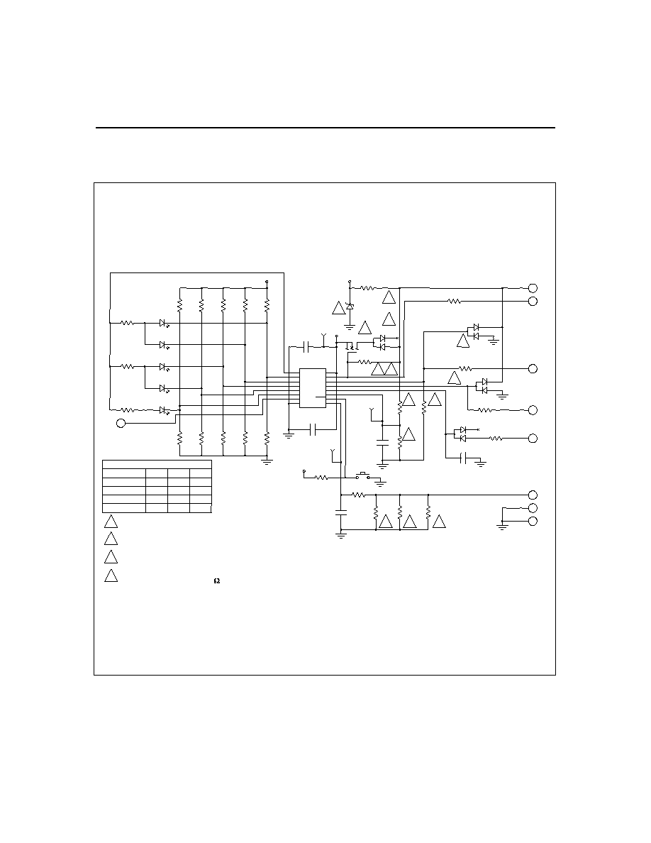
For PSTAT function, install R25 and D10.
If not using PSTAT, install 0 jumper at R26.
4
R7
69.8K
100K
100K
100K
1.3M
1.5M
1.1M
698K
4
4
4
Sense resistor value depends on application.
3
3
3
3
# OF CELLS
TABLE 1
1M
499K
300K
200K
5
4
3
2
R6
R2
1
1
1
2
2
2
2
2
PACK-
For 1 cell configuration install R11 and R9,
for greater than 1 cell configuration install Q1, D6, and R2.
See Table 1 for resistor values.
2
1
2150H/9-16-97/A
bq2150H Schematic
4
LED Option:
L = LEDs plus switch
Notes:
1.
Requires configuration sheet (Table 1)
2.
Example production part number: bq2150HLB-001
Ordering Information
bq2150H
B --
Customer Code:
Blank = Sample or Pre-production
1
KT = Evaluation system
XXX = Customer-specific; assigned by Unitrode
2
Package Option:
B = Board-level product
Device:
Li-Ion Power Gauge Module
bq2150H
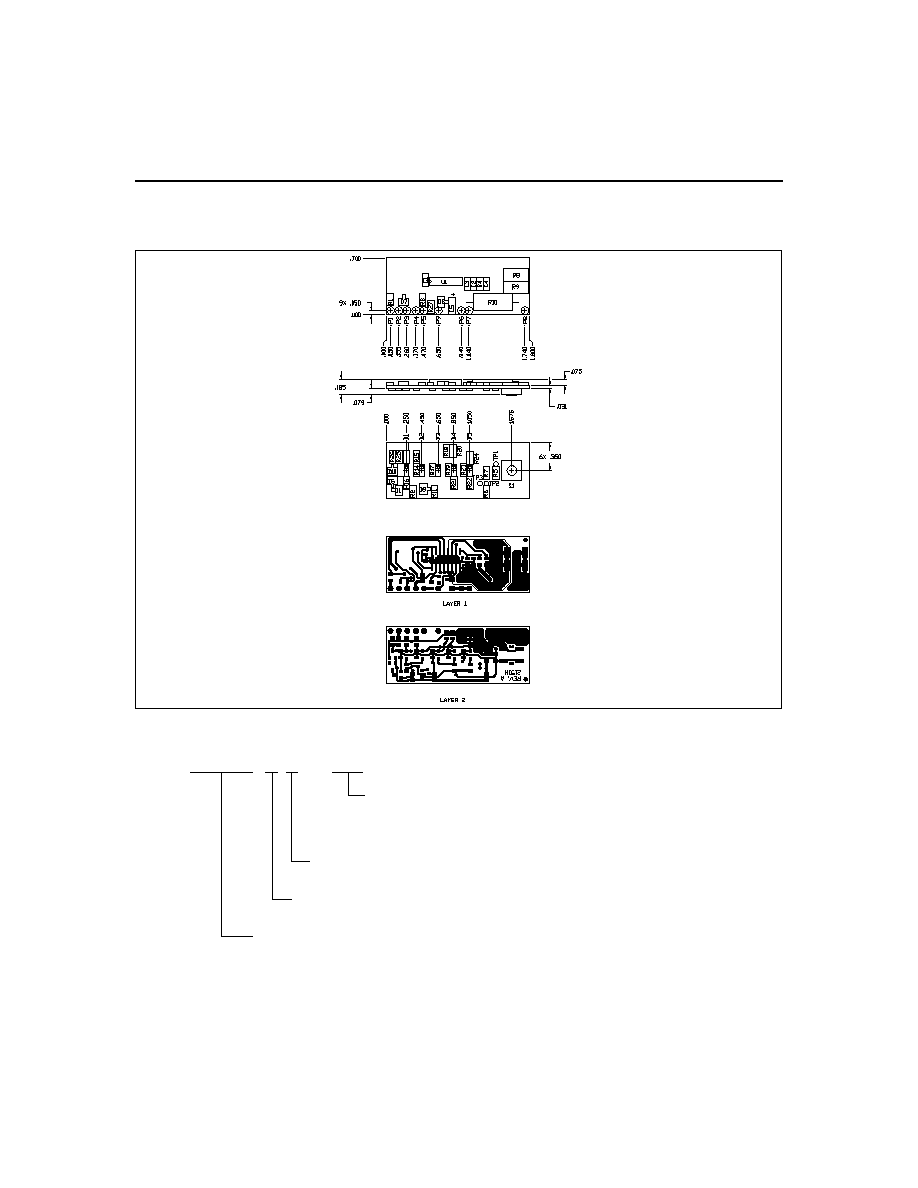
Preliminary
bq2150H Board

IMPORTANT NOTICE
Texas Instruments and its subsidiaries (TI) reserve the right to make changes to their products or to discontinue
any product or service without notice, and advise customers to obtain the latest version of relevant information
to verify, before placing orders, that information being relied on is current and complete. All products are sold
subject to the terms and conditions of sale supplied at the time of order acknowledgement, including those
pertaining to warranty, patent infringement, and limitation of liability.
TI warrants performance of its semiconductor products to the specifications applicable at the time of sale in
accordance with TI's standard warranty. Testing and other quality control techniques are utilized to the extent
TI deems necessary to support this warranty. Specific testing of all parameters of each device is not necessarily
performed, except those mandated by government requirements.
CERTAIN APPLICATIONS USING SEMICONDUCTOR PRODUCTS MAY INVOLVE POTENTIAL RISKS OF
DEATH, PERSONAL INJURY, OR SEVERE PROPERTY OR ENVIRONMENTAL DAMAGE ("CRITICAL
APPLICATIONS"). TI SEMICONDUCTOR PRODUCTS ARE NOT DESIGNED, AUTHORIZED, OR
WARRANTED TO BE SUITABLE FOR USE IN LIFE-SUPPORT DEVICES OR SYSTEMS OR OTHER
CRITICAL APPLICATIONS. INCLUSION OF TI PRODUCTS IN SUCH APPLICATIONS IS UNDERSTOOD TO
BE FULLY AT THE CUSTOMER'S RISK.
In order to minimize risks associated with the customer's applications, adequate design and operating
safeguards must be provided by the customer to minimize inherent or procedural hazards.
TI assumes no liability for applications assistance or customer product design. TI does not warrant or represent
that any license, either express or implied, is granted under any patent right, copyright, mask work right, or other
intellectual property right of TI covering or relating to any combination, machine, or process in which such
semiconductor products or services might be or are used. TI's publication of information regarding any third
party's products or services does not constitute TI's approval, warranty or endorsement thereof.
Copyright
©
1999, Texas Instruments Incorporated