Features
Complete and compact lithium ion gas gauge and
protection solution for three or four series cells
Accurate measurement of available battery
capacity
Provides overvoltage, undervoltage, and
overcurrent protection
Designed for battery pack integration
Small size
Includes bq2050 and bq2058 ICs
On-board charge and discharge control FETs
Low operating current for minimal battery drain
High side FET control
Battery capacity available through single-wire
serial port
"L" version includes 5 push-button activated LEDs
to display state-of-charge information
General Description
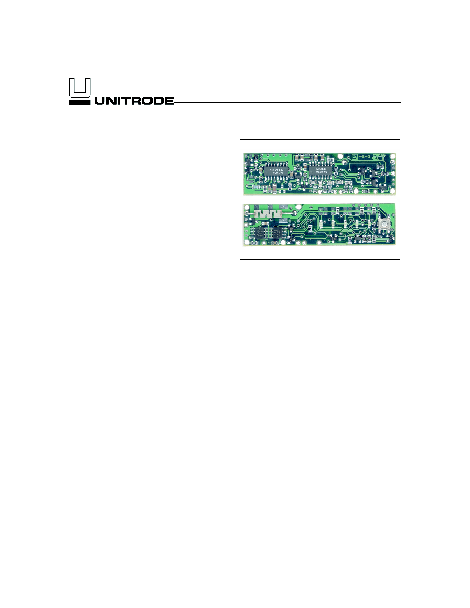
The bq2167 Power Gauge Module provides a complete and
compact battery management solution for Li-Ion battery
packs. Designed for battery pack integration, the bq2167
combines the bq2050 Power Gauge IC with the bq2058 Su-
pervisor IC on a small printed circuit board. The board in-
cludes all the necessary components to accurately monitor
battery capacity and protect the cells from overvoltage, un-
dervoltage, and overcurrent conditions. The board works
with three or four Li-Ion series cells.
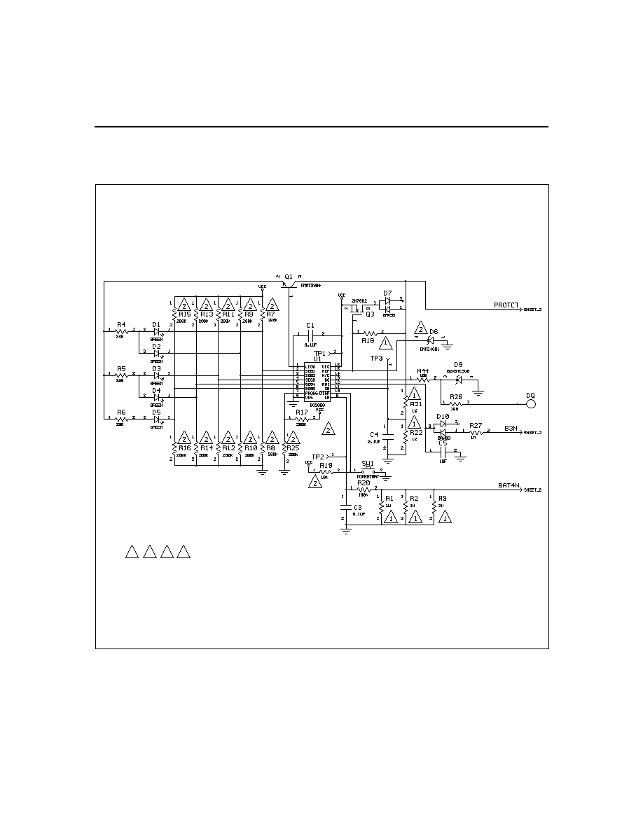
The Power Gauge IC uses the on-board sense resistor to
track charge and discharge activity of the battery pack.
Critical battery information can be accessed through the
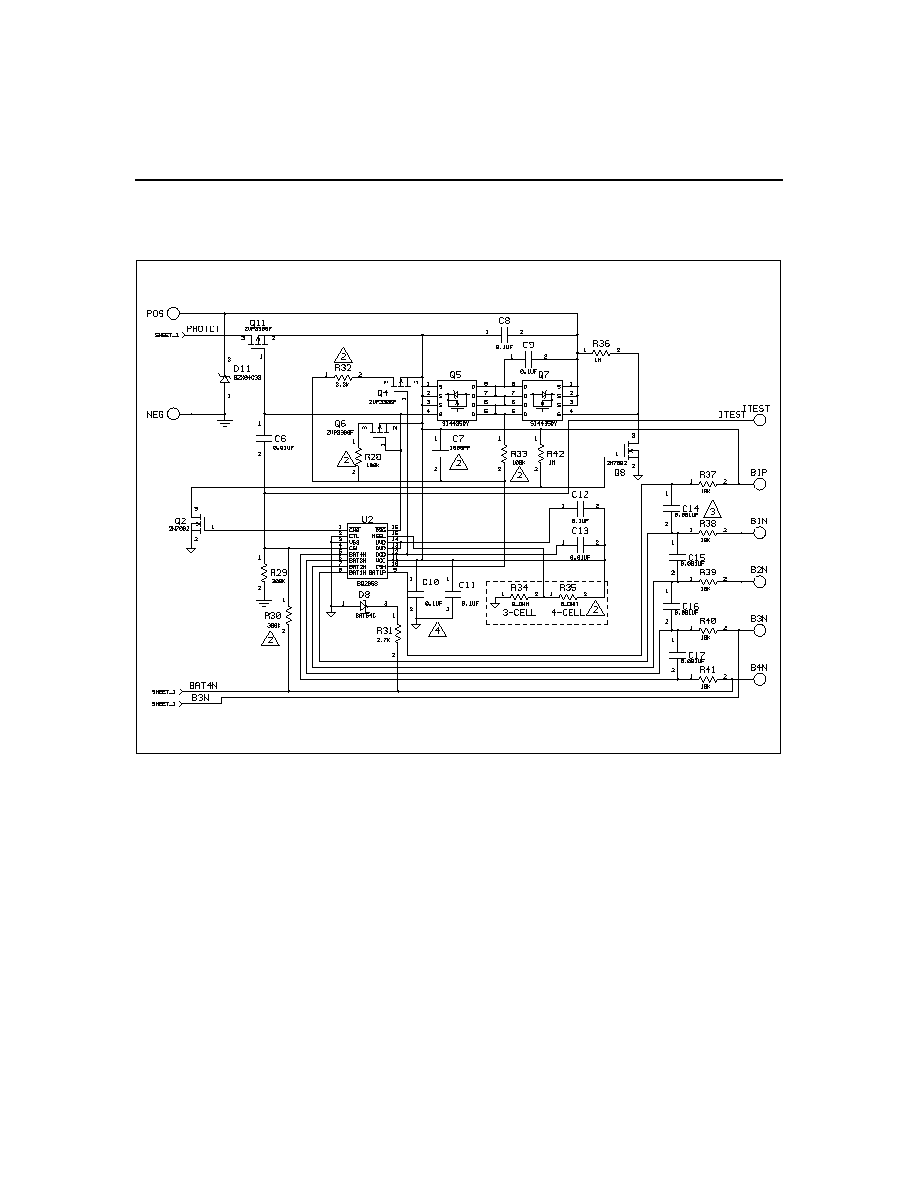
serial communications port at DQ. The supervisor cir-
cuit consists of the bq2058 and two FETs. The bq2058
controls the FETs to protect the batteries during
charge/discharge cycles and short circuit conditions. The
bq2167 provides contacts for the positive and negative
terminals of each battery in the stack. Please refer to
the bq2050 and bq2058 data sheets for the specifics on
the operation of the power gauge and supervisor ICs.
Unitrode configures the bq2167 based on the informa-
tion requested in Table 1. The configuration defines the
number of series cells, the nominal battery pack capac-
ity, the self-discharge rate, the Li-Ion battery type (coke
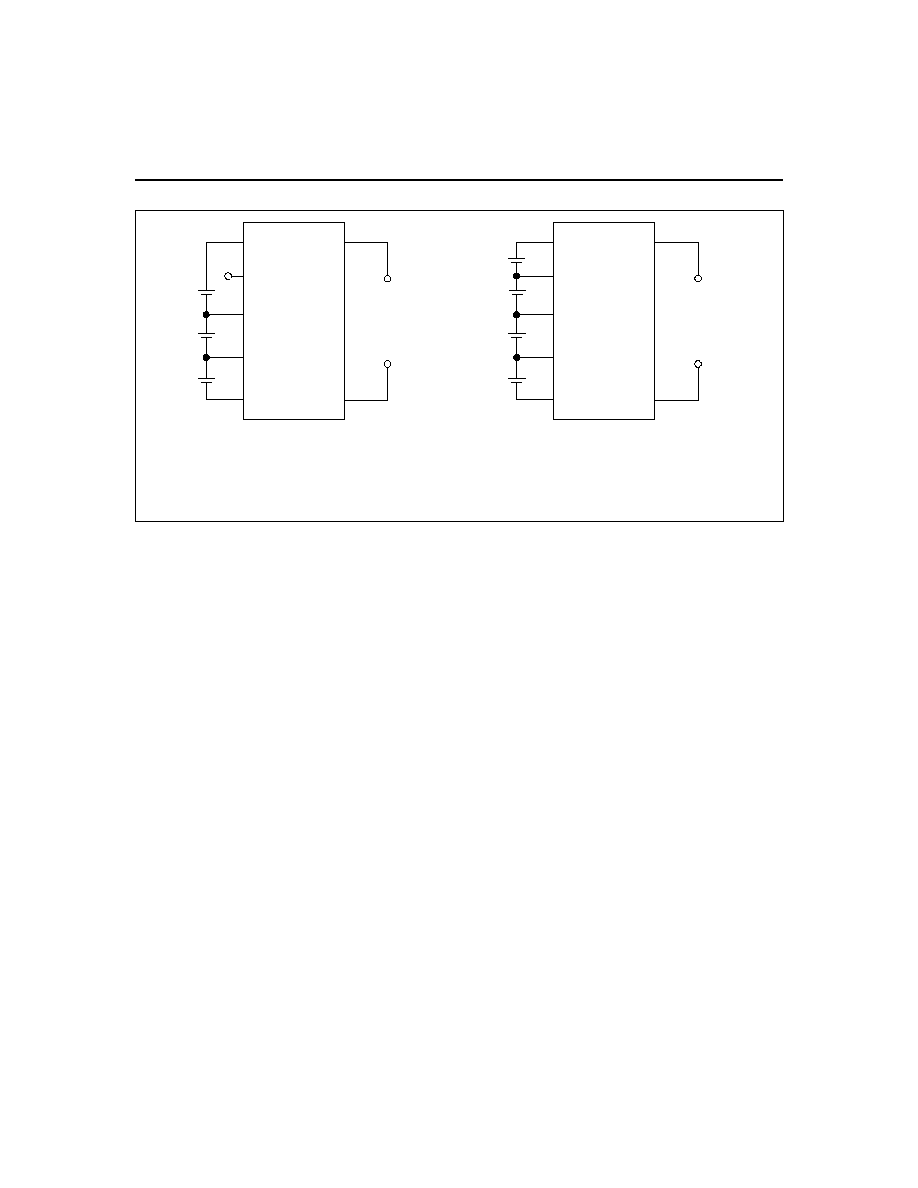
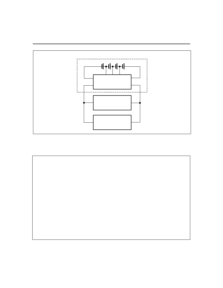
or graphite anode), and the threshold limits. Figure 1
shows how the module connects to the cells.
The bq2167L includes five LEDs to display remaining capac-
ity in 20% increments of the learned capacity. The LEDs are
activated with the onboard push-button switch.
A module development kit is also available for the
bq2167. The bq2167B-KT or the bq2167LB-KT includes
one configured module and the following:
1)
An interface board that allows connection to the
serial port of any AT-compatible computer.
2)
Menu driven software to display charge/discharge
activity and to allow user interface to the bq2050
from any standard DOS PC.
Pin Descriptions
POS
Pack positive
B1P
BAT
1P
/Battery 1 positive input
B1N
BAT
1N
/Battery 1 negative input
B2N
BAT
2N
/Battery 2 negative input
B3N
BAT
3N
/Battery 3 negative input
B4N
BAT
4N
/Battery 4 negative input
ITEST
Overcurrent test input
DQ
Serial communications port
NEG
Pack negative
1
bq2167
5/99 B
Li-Ion Power GaugeTM Module
with Pack Supervisor
2
bq2167
FG2167-1.eps
Battery Pack
B4N
B3N B2N B1N
B1P
NEG
POS
bq2167
Load
Charger
Cells
PACK+
PACK-
Figure 1. Module Connection Diagram
Customer Name: ___________________________________________________________________________
Contact: _________________________________________
Phone: ______________________________
Address: _________________________________________________________________________________
_________________________________________________________________________________
Sales Contact: ____________________________________
Phone: ______________________________
Number of series cells (3 or 4)
_____________
Coke or graphite cell anode
_____________
Battery pack capacity (mAh)
_____________
Discharge current into load (3.9A max.)
Min. ________ Avg. _________ Max. _________
Charge current (3.9A max)
_____________
Self-discharge compensation (Y/N)
_____________
Overvoltage threshold (4.25, 4.30, or 4.35V)
_____________
LEDs and switch (Y/N)
_____________
FAE approval: ____________________________________
Date: _______________________________
Table 1. bq2167 Module Configuration