www.ti.com
PRODUCT PREVIEW
FEATURES
APPLICATIONS
DESCRIPTION
+
Protector
R2
100 kW
Optional Battery Monitor/Gas Gauge
Pack +
Pack -
HDQ
1
2
3
4
5
V
CC
VSS
HDQ
SRN
SRP
GPIO
BAT
R3
5 kW
bq26150
R1
0.02 W
0.01 F
m
bq26150
SLUS641A ≠ JANUARY 2005 ≠ REVISED JULY 2005
BATTERY PACK SECURITY AND AUTHENTICATION IC
FOR PORTABLE APPLICATIONS (bqSECURETM)
∑
Small 5-Pin SC 70 package
∑
Provides Authentication of Battery Packs
Through a Programmable CRC With a 96-bit
∑
Cellular Phones
Unique Device ID
∑
PDA and Smart Phones
∑
16 Bytes of User-Programmable Nonvolatile
∑
MP3 Players
Memory
∑
Digital Cameras
∑
12.5 KV IEC ESD Protection on HDQ Input
∑
Internet Appliances
∑
Internal Time-Base Eliminates External
∑
Handheld Devices
Crystal Oscillator
∑
Low-Power Operating: <30
µ
A
∑
Single-Wire HDQ Interface
∑
Powered Directly From the Communication
Bus
∑
Pass-Through HDQ Version Supports Existing
Packs With Gas Gauges
The bq26150 provides a method to authenticate battery packs, ensuring that only packs manufactured by
authorized sub-contractors are used in the end application. The bq26150 uses a 96-bit unique device ID, device
unique 16-bit seed, and a 16-bit device specific CRC to provide security. The device ID, CRC seed, and CRC
polynomial coefficients are stored securely in each bq26150 device, allowing the host to authenticate each pack.
The bq26150 communicates to the system over a simple one-wire, bidirectional serial interface. The 5 kbits/s
HDQ bus interfaces reduces communications overhead in the external microcontroller. The bq26150 also uses
the HDQ bus to charge an external capacitor that provides power to the bq26150.
TYPICAL APPLICATION
Please be aware that an important notice concerning availability, standard warranty, and use in critical applications of Texas
Instruments semiconductor products and disclaimers thereto appears at the end of this data sheet.
bqSECURE is a trademark of Texas Instruments.
PRODUCT PREVIEW information concerns products in the forma-
Copyright © 2005, Texas Instruments Incorporated
tive or design phase of development. Characteristic data and other
specifications are design goals. Texas Instruments reserves the
right to change or discontinue these products without notice.
www.ti.com
PRODUCT PREVIEW
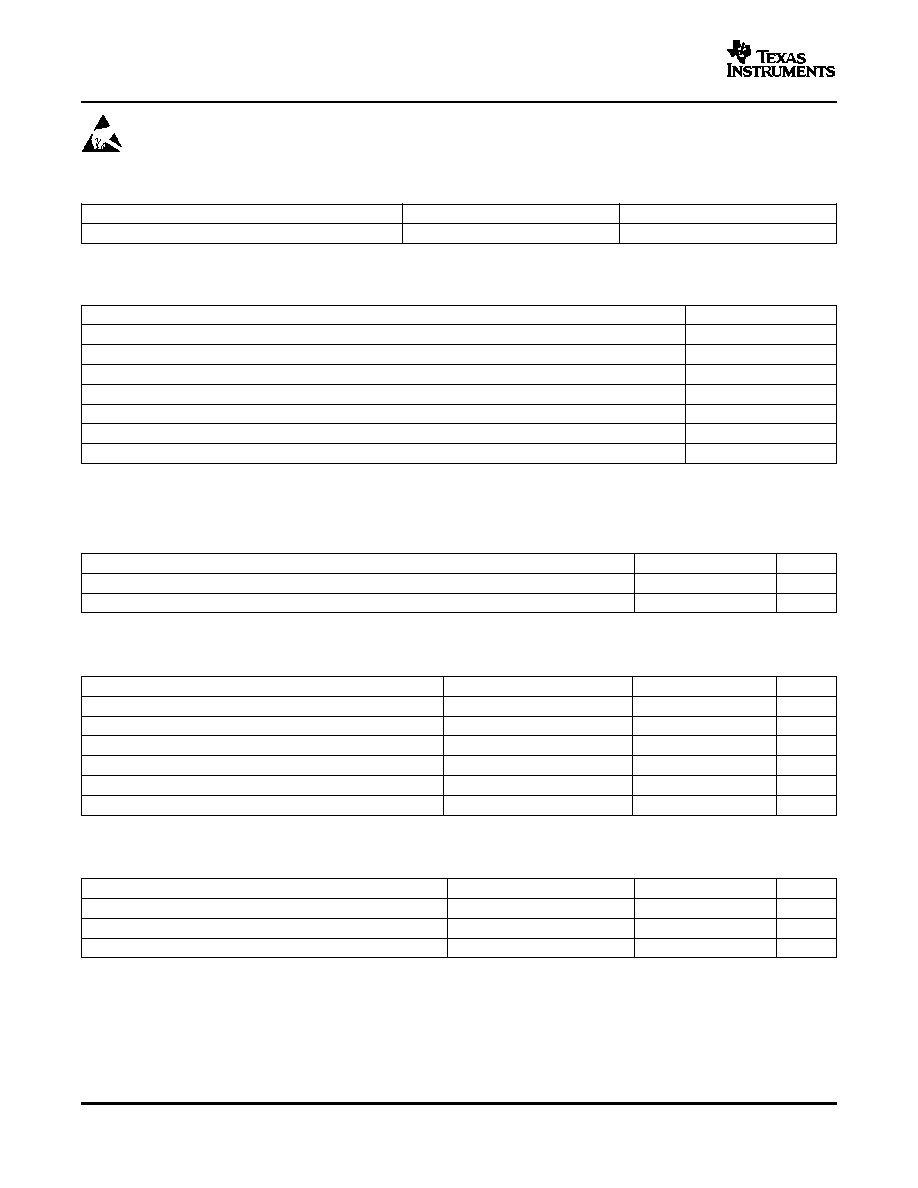
ABSOLUTE MAXIMUM RATINGS
(1)
RECOMMENDED OPERATING CONDITIONS
ELECTRICAL CHARACTERISTICS
HDQ AND HDQP PINS
bq26150
SLUS641A ≠ JANUARY 2005 ≠ REVISED JULY 2005
These devices have limited built-in ESD protection. The leads should be shorted together or the device
placed in conductive foam during storage or handling to prevent electrostatic damage to the MOS gates.
AVAILABLE OPTIONS
T
A
PACKAGE
PART NUMBER
≠20
∞
C to 70
∞
C
5-Lead SC 70
bq26150
UNIT
V
SS
Supply voltage (HDQ with respect to V
SS
)
≠0.3 V to 7.7 V
V
I
Input voltage (HDQP with respect to V
SS
)
≠0.3 V to 7 V
I
O
Output current (HDQ and HDQP)
5 mA
T
A
Operating free-air temperature range
≠20
∞
C to 70
∞
C
T
stg
Storage temperature range
≠65
∞
C to 150
∞
C
T
J
Junction temperature range
≠40
∞
C to 125
∞
C
Lead temperature (soldering, 10 sec)
300
∞
C
(1)
Stresses beyond those listed under absolute maximum ratings may cause permanent damage to the device. These are stress ratings
only, and functional operation of the device at these or any other conditions beyond those indicated under recommended operating
conditions is not implied. Exposure to absolute-maximum-rated conditions for extended periods may affect device reliability.
MIN
NOM
MAX
UNIT
Supply voltage, HDQ pull-up
2.5
5
V
T
J
Operating free-air temperature range
≠20
70
∞
C
All parameters over recommended operating temperature and supply voltage range (unless otherwise noted)
PARAMETER
TEST CONDITIONS
MIN
TYP
MAX
UNIT
C
I
Input capacitance
HDQ
400
pF
t
d1
Power up communication delay
Power capacitor charge time
100
ms
I
CC
V
CC
current
V
CC
> V
CC(min)
20
30
µ
A
V
(POR)
POR threshold
Low-to-high
1.5
V
Nonvolatile memory programming voltage
7.0
7.7
V
Nonvolatile memory programming supply current
≠40
∞
C and V
CC
= 2.75 V
308
µ
A
over recommended operating temperature and supply voltage range (unless otherwise noted)
PARAMETER
TEST CONDITIONS
MIN
TYP
MAX
UNIT
V
IH
Input high voltage
1.8
V
V
IL
Input low voltage
0.7
V
I
OL
Output low sink current
V
OL
= 0.4 V
1
mA
2
www.ti.com
PRODUCT PREVIEW
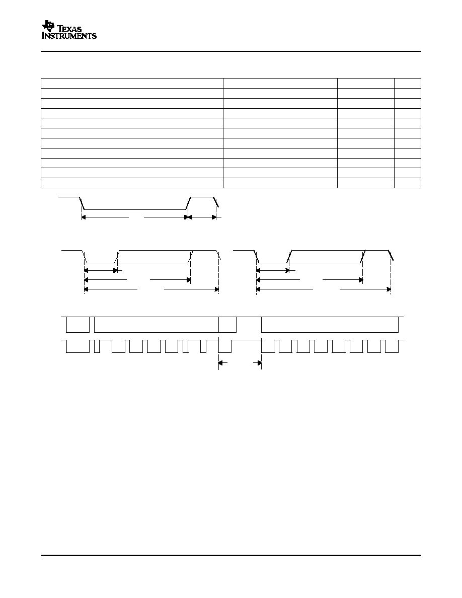
STANDARD SERIAL COMMUNICATION (HDQ) TIMING
BREAK
7 bit
ADDRESS
1 bit
R/W
8 bit
DATA
t
(B)
t
(BR)
(a) Break and Break Recovery Timing;
t
(HW0)
t
(HW1)
t
(CYCH)
t
(DW1)
t
(DW0)
t
(CYCD)
(b) Host Transmitted Bit Timing;
(c) bq26150 Transmitted Bit Timing;
t
(RSPS)
(d) bq26150 to Host Response Timing
bq26150
SLUS641A ≠ JANUARY 2005 ≠ REVISED JULY 2005
over recommended operating temperature and supply voltage range (unless otherwise noted) See
Figure 1
PARAMETER
TEST CONDITIONS
MIN
TYP
MAX
UNIT
Power up delay
Power capacitor charge time
100
ms
t
(B)
Break timing
190
µ
s
t
(BR)
Break recovery
40
µ
s
t
(CYCH)
Host bit window
190
µ
s
t
(HW1)
Host sends 1
0.5
50
µ
s
t
(HW0)
Host sends 0
86
145
µ
s
t
(RSPS)
bq26150 to host response
190
320
µ
s
t
(CYCD)
bq26150 bit window
190
250
µ
s
t
(DW1)
bq26150 sends 1
32
50
µ
s
t
(DW0)
bq26150 sends 0
80
145
µ
s
Figure 1. HDQ Bit Timing Diagrams
3
www.ti.com
PRODUCT PREVIEW
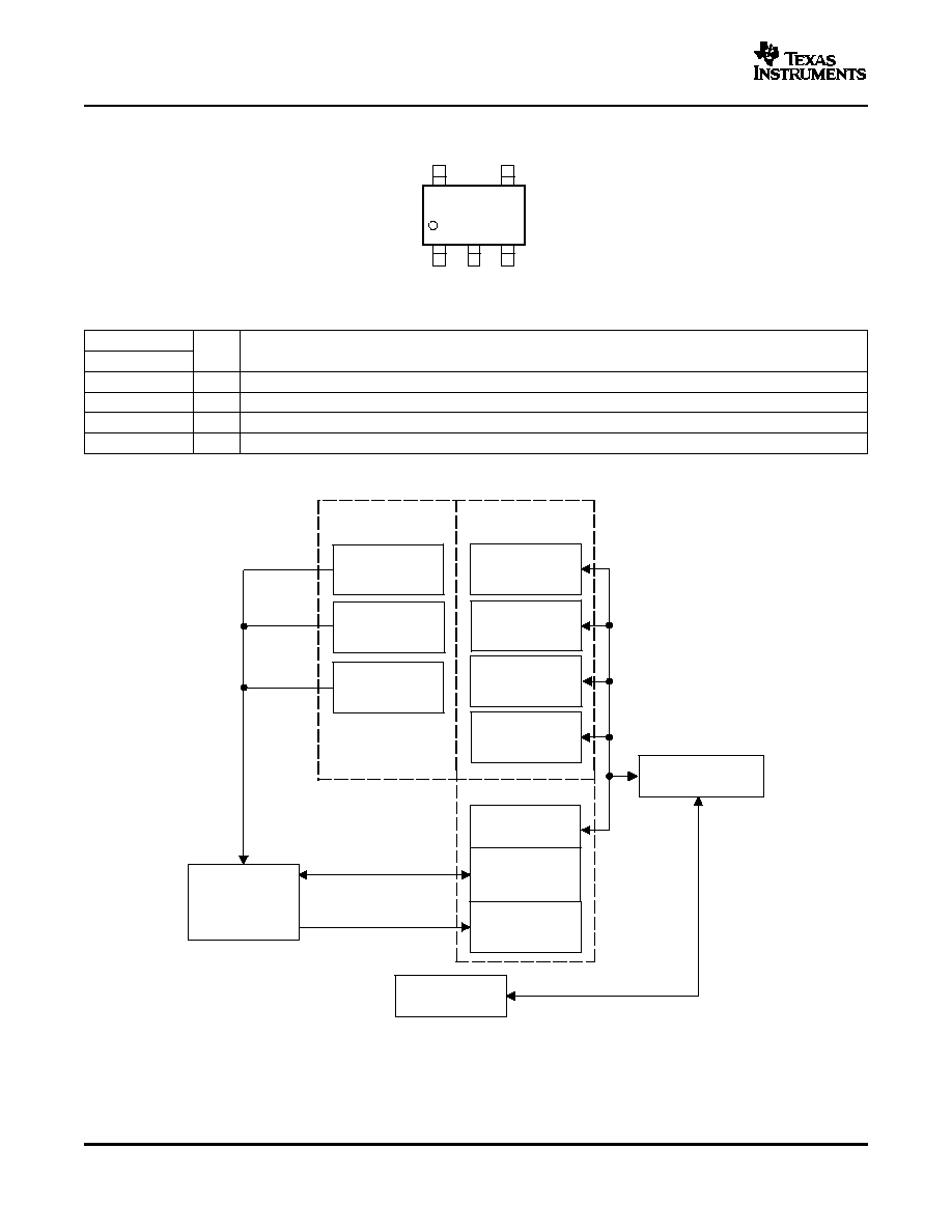
PIN ASSIGNMENT
3
2
4
5
1
V
SS
V
SS
HDQ
HDQP
PWR
Private Nonvolatile
Memory
Public Nonvolatile
Memory
96 bits
Encrypted ID
8 bits
Control
32 bits
Message
96 bits
Plaintext ID
HDQ
Communication
Power Control
Public RAM
128 bits
General Use
16 bits
16 bits
Plaintext
Polynomial
16 bits
Encrypted
Polynomial
Plaintext Seed
16 bits
Encrypted Seed
16 bits
Auth Code
Authentication
CRC
bq26150
SLUS641A ≠ JANUARY 2005 ≠ REVISED JULY 2005
TERMINAL FUNCTIONS
TERMINAL
I/O
DESCRIPTION
NAME
NO.
HDQ
1
I/O
Single-wire HDQ interface to host
VSS
2, 3
I
Ground
HDQP
4
I/O
Single-wire HDQ interface to 2nd HDQ device
PWR
5
I/O
Power capacitor
FUNCTIONAL BLOCK DIAGRAM
4
www.ti.com
PRODUCT PREVIEW
APPLICATION INFORMATION
+
Protector
R2
100 kW
Optional Battery Monitor/Gas Gauge
Pack +
Pack -
HDQ
1
2
3
4
5
V
CC
VSS
HDQ
SRN
SRP
GPIO
BAT
R3
5 kW
bq26150
R1
0.02 W
0.01 F
m
FUNCTIONAL DESCRIPTION
bq26150
SLUS641A ≠ JANUARY 2005 ≠ REVISED JULY 2005
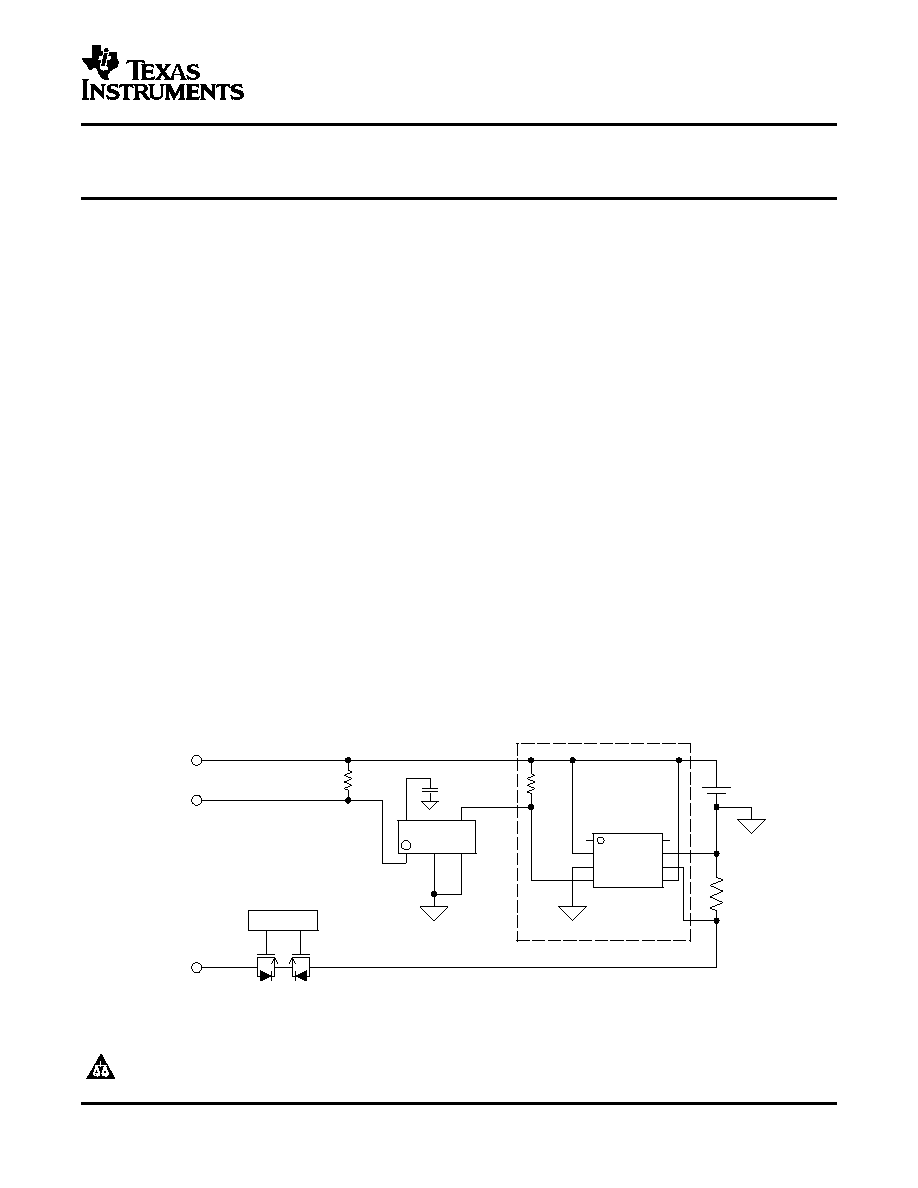
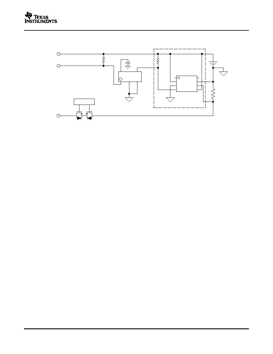
Figure 2. Typical Application Circuit
The bq26150 provides a simple and cost effective method to authenticate battery packs for end equipment.
Security is achieved through the use of a 16-bit CRC, a 16-bit CRC seed, a 96-bit device ID, and a 32-bit random
challenge. The CRC polynomial, CRC seed, and 96-bit ID are unique from device to device, and are stored as
encrypted text in public memory, and as plain text in private memory. The host system can decrypt the
polynomial, seed, and ID values using a shared key that is stored in end-equipments memory. The encryption
method and shared key used to store the polynomial coefficients and the device ID can be selected by the
manufacturer. Contact TI for information regarding specifics for encryption of the device ID and CRC polynomial
coefficients.
To authenticate a battery pack, the host reads the encrypted device ID, polynomial, and seed values. It decrypts
those values, then generates a 32-bit random challenge, which is transmitted to the bq26150. The bq26150 uses
the plain-text version of the polynomial coefficients and device ID, along with the 32-bit random challenge from
the host, to calculate the authentication CRC value. The host uses the polynomial coefficients, seed, and device
ID that it decrypted, along with the 32-bit random challenge it sent to the bq26150, to calculate the authentication
CRC value. When the host and bq26150 have completed the calculations, the host can read the authentication
CRC value the bq26150 computed and compare to its own value. If the values match, the battery pack is
authenticated.
The bq26150 has a communication pass-through mode that allows it to be used in systems with an existing HDQ
based battery monitor or gas gauge. Once the battery pack is authenticated, the bq26150 can be put in
continuous pass-through mode, allowing the host system to communicate with a second HDQ device with no
additional overhead. A one-time pass-through mode is also available, allowing the host to communicate once to
the second HDQ device as needed.
The bq26150 obtains the power needed to run from the HDQ bus. An external capacitor is charged when the bus
is high and discharges while the bus is low. If the bq26150 is not authenticating or communicating and the HDQ
bus is low, the power is reduced and it enters sleep mode. If the bus is held low until the capacitor fully
discharges, the bq26150 is disabled.
5