 | –≠–ª–µ–∫—Ç—Ä–æ–Ω–Ω—ã–π –∫–æ–º–ø–æ–Ω–µ–Ω—Ç: BQ2902 | –°–∫–∞—á–∞—Ç—å:  PDF PDF  ZIP ZIP |
1
Features
Safely charges two rechargeable
alkaline batteries such as Re-
newal
Æ
from Rayovac
Æ
Terminates pulsed charge with
maximum voltage limit
Contains LED charge status out-
put
Features a pin-selectable
low-battery cut-off
Pre-charge qualification indicates
fault condition
Available in 8-pin 300-mil DIP or
150-mil SOIC
General Description
The bq2902 is a low-cost charger for
rechargeable alkaline batteries such
as Renewal
Æ
batteries from Rayovac
Æ
.
The bq2902 combines sensitive, full-
charge detection for two recharge-
able alkaline cells, with a low-battery
cut-off for overdischarge protection.
Designed for system integration
into a two-cell system, the bq2902
can improve the service life of the
rechargeable alkaline cells by prop-
erly managing the charge and dis-
charge. The bq2902 requires a
voltage limited current source to
generate the proper charge pulses
for the Renewal
Æ
cell. Each cell is
individually monitored to ensure
full charge without a damaging
overcharge.
Charge completion is indicated
when the average charge rate falls
below approximately 3% of the fast
charge rate. A status output is pro-
vided to indicate charge in progress,
charge complete, or fault indication.
The bq2902 avoids over-depleting
the battery by using the internal
end-of-discharge control circuit.
The bq2902 also eliminates the
external power switching transis-
tors needed to separately charge
individual Renewal cells.
For safety, charging is inhibited if
the per-cell voltage is greater than
3.0V during charge (closed-circuit
voltage), or if the cell voltage is less
than 0.4V (open-circuit voltage).
Rechargeable Alkaline Charge/Discharge
Controller IC
bq2902
5/99 C
1
PN290201.eps
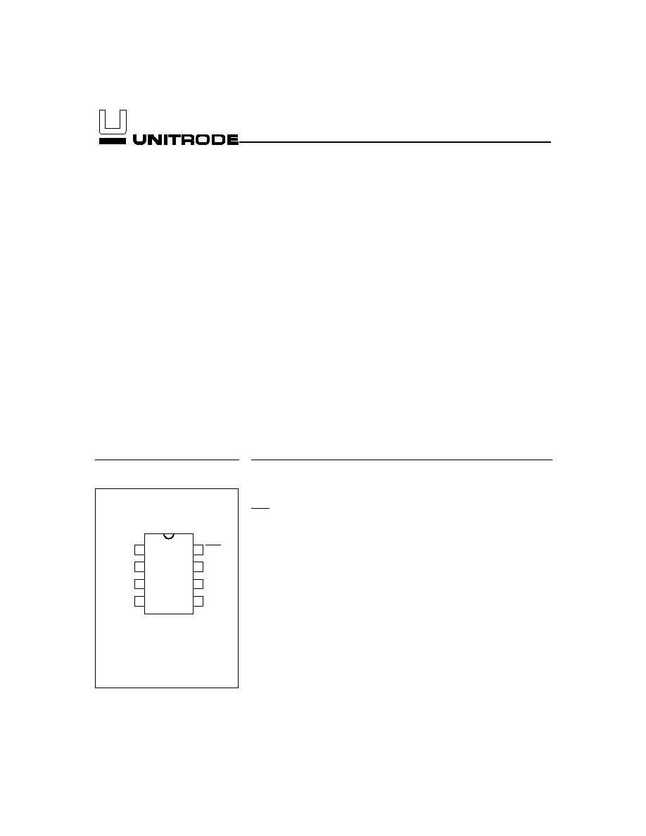
8-Pin Narrow DIP
or SOIC
2
3
4
8
7
6
5
VSEL
BAT1N
BAT1P
DC
CHG
VSS
VSS
LRTN
DC
Charging supply input
CHG
Battery status output
BAT
1P
Battery 1 positive input
BAT
1N
Battery 1 negative input
V
SS
Battery 2 negative input
IC ground
LRTN
System load return
V
SEL
End-of-discharge voltage
select input
Pin Names
Pin Connections
Pin Descriptions
DC
DC supply input
This input is used to charge the rechargeable
alkaline cells and power the bq2902 during
charge. To charge the batteries, this input
should be connected to a current-source lim-
ited to 300 mA. If the DC input current is
greater than 300mA, the power dissipation
limits of the package may be exceeded. The
DC input should also be capable of supplying
a minimum of 3.3V and should not exceed
5.5V.
CHG
Charge status
This open-drain output is used to signify the
battery charging status and is valid only
when DC is applied.
V
SEL
End-of-discharge select input
This three-level input selects the desired
end-of-discharge cut-off voltage for the
bq2902. V
SEL
= BAT
1P
selects an EDV of
1.10V. V
SEL
floating selects EDV = 1.0V. V
SEL
= V
SS
selects EDV = 0.9.V
BAT
1P
Battery 1 positive input
This input connects to the positive terminal
of the battery designated BAT
1
(see Figure
3). This pin also provides power to the bq2902
when DC is not present.
BAT
1N
Battery 1 negative input
This input connects to the negative terminal
of the battery designated BAT
1
(see Figure 3).
V
SS
Battery 2 negative input/IC ground
This input connects to the negative terminal
of the battery designated BAT
2
(see Figure 3).
LRTN
Load return
This open-drain pull-down output is typi-
cally used as a low-side switch. High-side
load switching is also possible with the addi-
tion of an external P-FET.
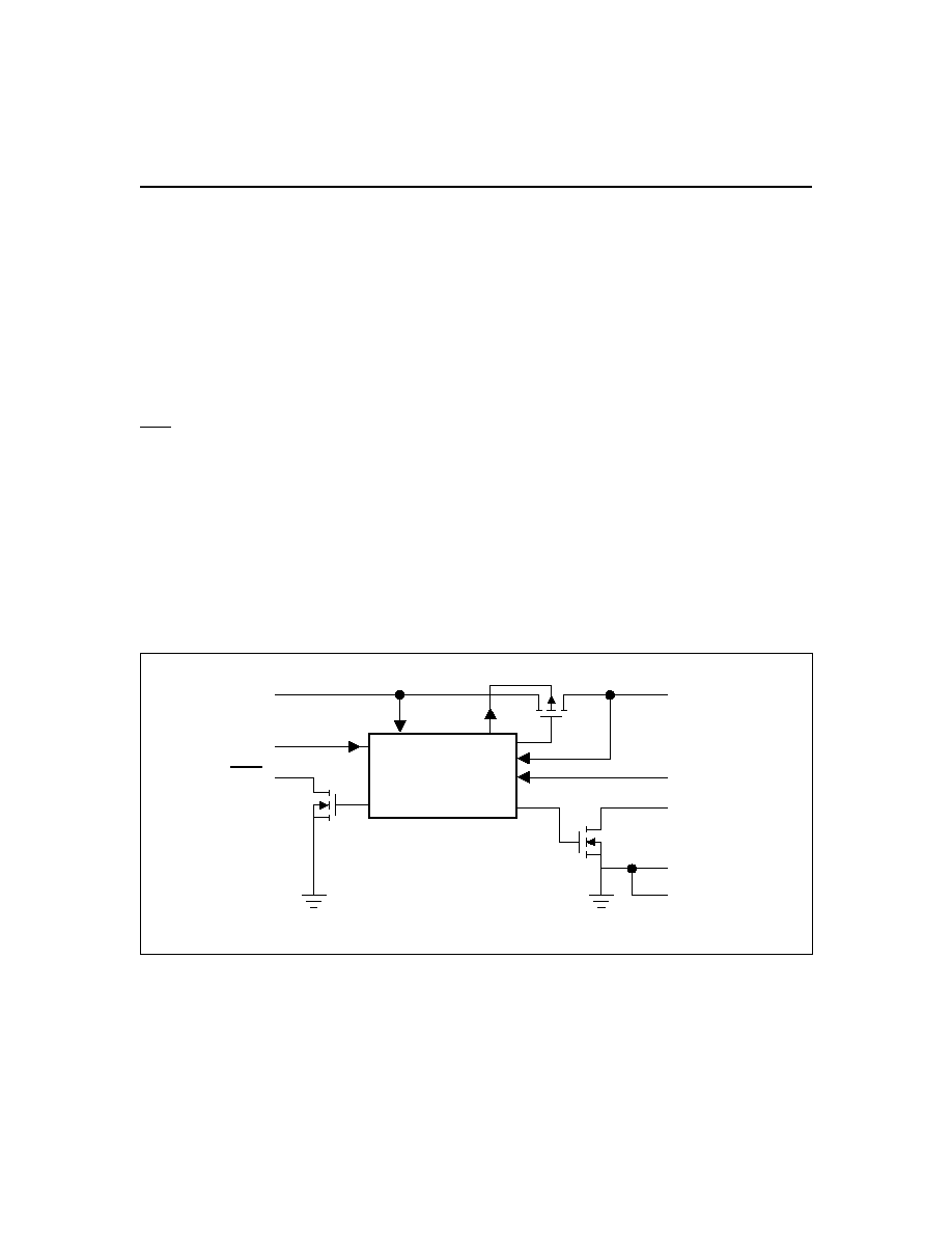
Functional Description
Figure 1 is a block diagram outlining the major compo-
nents of the bq2902.
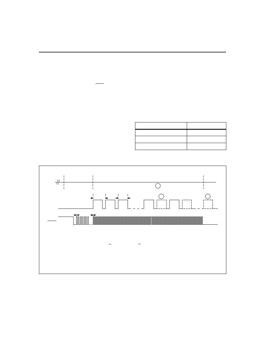
Figure 2 illustrates the charge control and display
status during a bq2902 cycle. Table 1 outlines the vari-
2
bq2902
BD290201.eps
Control/Status
Logic
DC
VSEL
CHG
BAT1P
BAT1N
LRTN
VSS
VSS
3
2
5
6
7
4
1
8
Figure 1. Functional Block Diagram

ous operational states and their associated conditions
which are described in detail in the following section.
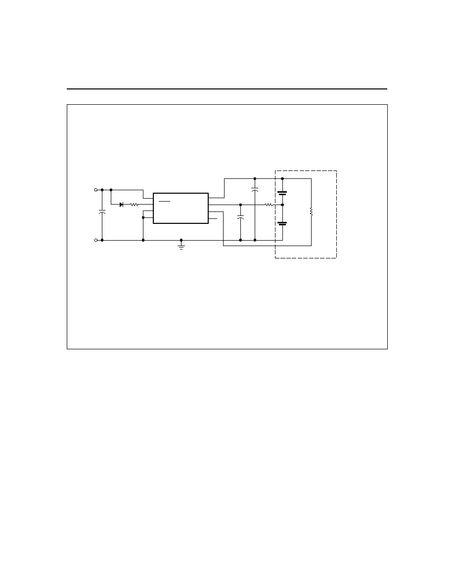
Figure 3 is an application example.
Charge Initiation
The bq2902 always initiates and performs a charge cycle
whenever a valid DC input is applied. A charge cycle
consists of pulse charging the battery and then checking
for a termination condition.
The charging section ex-
plains charging in greater detail.
Charge Pre-Qualification
After DC is applied, the bq2902 checks the open-circuit
voltage (V
OCV
) of each cell for an undervoltage condition
(V
MIN
= 0.4V) and begins a charge cycle when the V
OCV
of all cells is above V
MIN
. If V
OCV
of any cell is below
V
MIN
, the bq2902 enters a charge-pending mode and in-
dicates a fault condition (see Table 1). The bq2902 re-
mains in a charge-pending mode until V
OCV
of each cell
is above V
MIN
.
Charge Termination
Once a charge cycle begins, the bq2902 terminates
charge when the average charge rate falls below 3% of
the maximum charge rate. The bq2902 also terminates
charge when the closed-circuit voltage (V
CCV
) of any cell
exceeds 3.0V (V
FLT
) during charge and indicates a fault
condition on the CHG output (see Table 1).
Charge Re-Initiation
If DC remains valid, the bq2902 suspends all charge
activity after full-charge termination. A charge cycle is
re-initiated when all cell potentials fall below 1.4V. The
rechargeable alkaline cells, unlike other rechargeable
chemistries, do not require a maintenance charge to
keep the cells in a fully charged state. The self-discharge
rate for the Renewal cells is typically 4% per year at
room temperature.
Charge Status Indication
Table 1 and Figure 2 outline the various charge action
states and the associated BAT
1P
, and CHG output
states. The charge status output is designed to work
with an LED indicator. In all cases, if DC is not present
at the DC pin, or if the DC supply is less than the volt-
age at the BAT
1P
pin, the CHG output is held in a high-
impedance condition.
Charging
The bq2902 controls charging by periodically connecting
the DC current-source to the battery stack, not to the in-
dividual battery cells.
The charge current is pulsed
from the internal clock at approximately a 80Hz rate on
the BAT
1P
pin.
The bq2902 pulse charges the battery for approximately
10ms of every 12.5ms, when conditions warrant. The
bq2902 measures the open-circuit voltage (V
OCV
) of each
battery cell during the idle period. If a single-cell poten-
3
bq2902
Charge Action State
Conditions
BAT
1P
Input
CHG
Output
DC absent
V
DC
< V
BAT1P
Low battery detection per V
SEL
Z
Charge initiation
DC applied
-
-
Charge pending/
fault
V
OCV
< 0.4V
1
or V
CCV
> 3.0V
2
-
2
3
sec = Low
2
3
sec = Z
Charge pulse
V
OCV
1.63V before pulse
Charge pulsed @ 80Hz per Figure 2
1
6
sec = Low
1
6
sec = Z
Pulse skip
V
OCV
> 1.63V
before pulse
Pulse skipped per Figure 2
1
6
sec = Low
1
6
sec = Z
Charge complete
Average charge rate falls below 3% of
the fast charge rate
Charge complete
Low
Notes:
1.
V
OCV
= Open-circuit voltage of each cell between positive and negative leads.
2.
V
CCV
= Closed-circuit voltage.
Table 1. bq2902 Operational Summary
tial of any battery is above the maximum open-circuit
voltage (V
MAX
= 1.63V
±3%), the following pulses are
skipped until all cell potentials fall below the V
MAX
limit. Charging is terminated when the average charge
rate falls below approximately 3% of the maximum
charge rate. Once charging is terminated, the internal
charging FET remains off, and the CHG output becomes
active per Table 1 and Figure 2. With DC applied, the
internal discharge FET will always remain on.
End-of-Discharge Control
When DC is not present or less than the voltage present
on the BAT
1P
pin, the bq2902 power is supplied by the
voltage present at the BAT
1P
pin. In this state, the bat-
teries discharge down to the level determined by the
V
SEL
pin. The bq2902 monitors the cell voltage of the re-
chargeable alkaline cells.
If the voltage across any cell is below the voltage speci-
fied by the V
SEL
input, the bq2902 disconnects the bat-
tery stack from the load by turning the internal
discharge FET off. The discharge FET remains off until
either the batteries are replaced or DC is reapplied, ini-
tiating a new charge cycle. After disconnecting the bat-
tery stack from the load, the standby current in the
bq2902 is reduced to less than 1
µA. The end-of-
discharge voltage (V
EDV
) is selectable by connecting the
V
SEL
pin as outlined in Table 2. Typically, higher dis-
charge loads (>200mA) should use a lower discharge
voltage cut-off to maximize battery capacity.
4
bq2902
End-of-Discharge Voltage
Pin Connection
1.10V
V
SEL
= BAT
1P
1.00V
V
SEL
= Z
0.90V
V
SEL
= V
SS
Table 2. bq2902 EDV Selections
TD290201.eps
DC Valid
BAT1P
Charge
Complete
12.5ms
Notes:
Pending
Charging 1
2
3
CHG
1. Charging: 0.4 < VOCV 1.63V, VCCV 3.0V.
2. Pulses skipped when VOCV > 1.63V.
3. Charge complete when average charge falls below 3% of fast charge rate
<
<
2/3 sec.
1/6 sec.
10ms
Figure 2. bq2902 Application Diagram
5
bq2902
FG290201.eps
DC
CHG
VSS
VSS
BAT1P
BAT1N
LRTN
VSEL
bq2902
Battery 1
Battery 2
Load
C2
R2
C3
R1
D1
LED
C1
DC+
DC-
4
8
7
6
3
2
5
1
Battery and Load
Note: Load must be disconnected from
battery stack while charging.
Figure 3. bq2902 Application Example, 1.0V EDV