 | ÐлекÑÑоннÑй компоненÑ: BQ2945 | СкаÑаÑÑ:  PDF PDF  ZIP ZIP |
Äîêóìåíòàöèÿ è îïèñàíèÿ www.docs.chipfind.ru

1
Features
Provides accurate measurement
of available charge in NiCd,
NiMH, and Li-Ion batteries
Supports SBS v1.0 data set and
two-wire interface
Two programmable general
purpose output ports for added
flexibility
Designed for battery pack inte-
gration
-
Low operating current
-
Complete circuit can fit on less
than ¾ square inch of PCB
space
Supports SBS charge control
commands for NiCd, NiMH, and
Li-Ion
Drives a five-segment LED dis-
play for remaining capacity
indication
16-pin narrow SOIC
General Description
The bq2945 Gas Gauge IC With
SMBus Interface is intended for
battery-pack or in-system installa-
tion to maintain an accurate record
of available battery charge. The
bq2945 directly supports capacity
monitoring for NiCd, NiMH, and
Li-Ion battery chemistries.
The bq2945 uses the System Man-
agement Bus v1.0 (SMBus) protocol
and supports the Smart Battery
Data (SBData) commands. The
bq2945 also supports the SBData
charge control functions.
Battery
state-of-charge, remaining capacity,
remaining time, and chemistry are
av a i l a b l e o v e r t h e s e r i a l l i n k .
Battery-charge state can be directly
indicated using a five-segment LED
display to graphically depict battery
full-to-empty in 20% increments.
The bq2945 estimates battery self-
discharge based on an internal
timer and temperature sensor and
user-programmable rate informa-
tion stored in external EEPROM.
The bq2945 also automatically re-
calibrates or "learns" battery capac-
ity in the full course of a discharge
cycle from full to empty.
The bq2945 may operate directly
from three nickel chemistry cells.
With the REF output and an exter-
nal transistor, a simple, inexpensive
regulator can be built to provide V
CC
for other battery cell configurations.
An external EEPROM programs
initial values into the bq2945 and is
necessary for proper operation.
bq2945
Gas Gauge IC with SMBus Interface
V
CC
3.06.5V
LED
1
LED segment 1/
EEPROM clock
LED
2
LED segment 2/
EEPROM data
LED
3
LED segment 3
LED
4
LED segment 4
LED
5
LED segment 5
CP
1
Control pin 1
V
SS
System ground
1
PN294501.eps
16-Pin Narrow SOIC
2
3
4
5
6
7
8
16
15
14
13
12
11
10
9
VOUT
REF
SMBC
SMBD
CP2
SB
DISP
SR
VCC
LED1/ESCL
LED2/ESDA
LED3
LED4
LED5
CP1
VSS
SR
Sense resistor input
DISP
Display control input
SB
Battery sense input
CP
2
Control pin 2
SMBD
SMBus data input/output
SMBC
SMBus clock
REF
Voltage reference output
V
OUT
EEPROM supply output
6/99 C
Pin Connections
Pin Names

Pin Descriptions
V
CC
Supply voltage input
LED
1
LED
5
LED display segment outputs
Each output may drive an external LED.
ESCL
Serial memory clock
Output used to clock the data transfer be-
tween the bq2945 and the external non-
volatile configuration memory.
ESDA
Serial memory data and address
Bidirectional pin used to transfer ad-
dress and data to and from the bq2945
and the external nonvolitile configura-
tion memory.
CP
1
CP
2
Control pins 1 and 2
These open-drain outputs can be con-
trolled by an SMBus command from the
host. CP
2
can also act as a digital input.
V
SS
Ground
SR
Sense resistor input
The voltage drop (V
SR
) across pins SR and
V
SS
is monitored and integrated over time
to interpret charge and discharge activity.
The SR input is connected to the sense re-
sistor and the negative terminal of the
battery. V
SR
< V
SS
indicates discharge, and
V
SR
> V
SS
indicates charge. The effective
voltage drop, V
SRO
, as seen by the bq2945
is V
SR
+ V
OS
. (See Table 3.)
DISP
Display control input
DISP high disables the LED display. DISP
floating allows the LED display to be active
during charge if the rate is greater than
100mA. DISP low activates the display for
4 seconds.
SB
Secondary battery input
Monitors the pack voltage through a high-
impedance resistor divider network.
The
pack voltage is reported in the SBD register
function Voltage (0x09) and is monitored for
end-of-discharge voltage and charging volt-
age parameters.
SMBD
SMBus data
Open-drain bidirectional pin used to trans-
fer address and data to and from the
bq2945.
SMBC
SMBus clock
Open-drain bidirectional pin used to clock
the data transfer to and from the bq2945.
REF
Reference output for regulator
REF provides a reference output for an op-
tional FET-based micro-regulator.
V
OUT
Supply output
Supplies power to the external EEPROM
configuration memory.
2
bq2945
Functional Description
General Operation
The bq2945 determines battery capacity by monitoring
the amount of charge put into or removed from a re-
chargeable battery.
The bq2945 measures discharge
and charge currents, estimates self-discharge, and
monitors the battery for low-battery voltage thresholds.
The charge is measured by monitoring the voltage
across a small-value series sense resistor between the
battery's negative terminal and ground. The available
battery charge is determined by monitoring this voltage
over time and correcting the measurement for the envi-
ronmental and operating conditions.
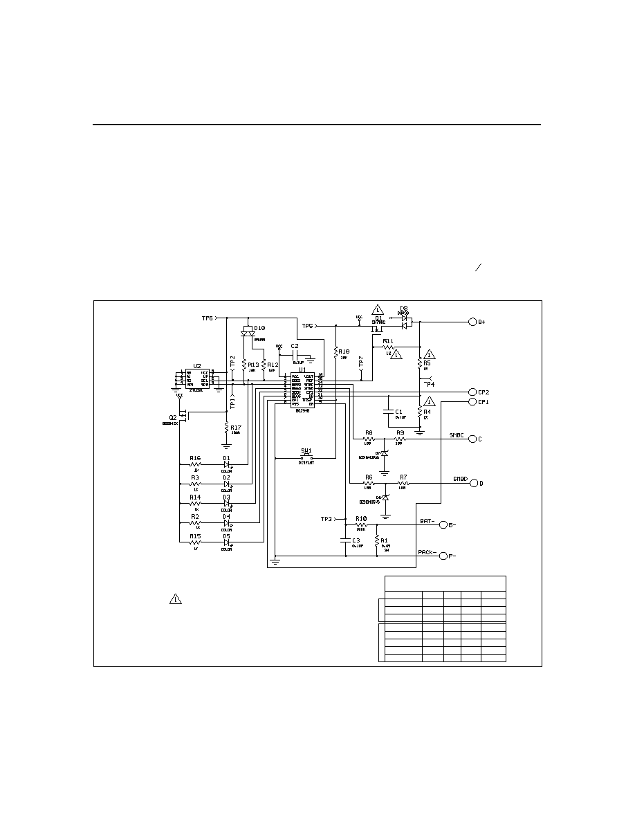
Figure 1 shows a typical battery pack application of the
bq2945 using the LED capacity display, the serial port,
and an external EEPROM for battery pack program-
ming information. The bq2945 must be configured and
calibrated for the battery-specific information to ensure
proper operation. Table 1 outlines the configuration in-
formation that must be programmed in the EEROM.
An internal temperature sensor eliminates the need
for an external thermistor--reducing cost and compo-
nents.
An internal, temperature-compensated time-
base eliminates the need for an external resonator,
further reducing cost and components. The entire cir-
cuit in Figure 1 can occupy less than
3
4
square inch of
board space.
3
bq2945
100K
100K
100K
100K
100K
100K
100K
86.5K
BSS138
BSS138
BSS138
2N7002
BSS138
2N7002
2N7002
2N7002
R5
R4
R11
Q1
No. of Cells
Chart 1
Li-Ion
NiMH
3
2
4
6
8
9
10
12
499K
301K
499K
499K
499K
698K
698K
806K
806K
806K
604K
604K
604K
909K
909K
909K
See Chart 1 for resistor values and
Q1 FET selection
Figure 1. Battery Pack Application Diagram--LED Display
Notes:
R4, R5, and R11 values depend on the battery voltage.
R12 and R13 nominal values must be 10k

4
bq2945
Parameter Name
Address
Description
Length
Units
EEPROM length
0x00
Number of EEPROM data locations
must = 0x64
8 bits
NA
EEPROM check1
0x01
EEPROM data integrity check byte
must = 0x5b
8 bits
NA
Remaining time alarm
0x02/0x03 Sets RemainingTimeAlarm (0x02)
16 bits
minutes
Remaining capacity alarm
0x04/0x05 Sets RemainingCapacityAlarm (0x01)
16 bits
mAh
Reserved
0x06/0x07 Reserved for future use
16 bits
NA
Initial charging current
0x08/0x09 Sets the initial charging current
16 bits
mA
Charging voltage
0x0a/0x0b Sets ChargingVoltage (0x15)
16 bits
mV
Battery status
0x0c/0x0d Initializes BatteryStatus (0x16)
16 bits
NA
Cycle count
0x0e/0x0f Initializes and stores CycleCount (0x17)
16 bits
cycles
Design capacity
0x10/0x11 Sets DesignCapacity (0x18)
16 bits
mAh
Design voltage
0x12/0x13 Sets DesignVoltage (0x19)
16 bits
mV
Specification information
0x14/0x15 Programs SpecificationInfo (0x1a)
16 bits
NA
Manufacturer date
0x16/0x17 Programs ManufactureDate (0x1b)
16 bits
NA
Serial number
0x18/0x19 Programs SerialNumber (0x1c)
16 bits
NA
Fast-charging current
0x1a/0x1b Sets ChargingCurrent (0x14)
16 bits
mA
Maintenance-charge current
0x1c/0x1d Sets the trickle current request
16 bits
mA
Reserved
0x1e/0x1f Reserved must = 0x0000
16 bits
mAh
Manufacturer name
0x20-0x2b Programs ManufacturerName (0x20)
96 bits
NA
Current integration gain
0x2c/0x2d Programs the sense resistor scale
16 bits
NA
Reserved
0x2e/0x2f Reserved for future use
16 bits
NA
Device name
0x30-0x37 Programs DeviceName (0x21)
64 bits
NA
Li-Ion taper current
0x38/0x39
Sets the upper limit of the taper current for charge
termination
16 bits
mA
Maximum overcharge limit
0x3a/0x3b Sets the maximum amount of overcharge
16 bits
NA
Reserved
0x3c
Reserved must = 0x00
8 bits
NA
Access protect
0x3d
Locks commands outside of the SBS data set
8 bits
NA
FLAGS1
0x3e
Initializes FLAGS1
8 bits
NA
FLAGS2
0x3f
Initializes FLAGS2
8 bits
NA
Device chemistry
0x40-0x47 Programs DeviceChemistry (0x22)
64 bits
NA
Battery voltage offset
0x48
Voltage calibration value
8 bits
NA
Temperature offset
0x49
Temperature calibration value
8 bits
NA
Maximum temperature and
T step
0x4a
Sets the maximum charge temperature and the
T
step for
T/t termination
8 bits
NA
Table 1. Configuration Memory Map

5
bq2945
Parameter Name
Address
Description
Length
Units
Charge efficiency
0x4b
Sets the high/low charge rate efficiencies
8 bits
NA
Full-charge percentage
0x4c
Sets the percent at which the battery is consid-
ered fully charged
8 bits
NA
Digitial filter
0x4d
Sets the minimum charge/discharge threshold
8 bits
NA
Reserved
0x4e
Reserved for future use
8 bits
NA
Self-discharge rate
0x4f
Sets the battery's self-discharge rate
8 bits
NA
Manufacturer data
0x50-0x55 Programs ManufacturerData (0x23)
48 bits
NA
Voltage gain1
0x56/0x57 Battery divider calibration value
16 bits
NA
Reserved
0x58-0x59 Reserved
16 bits
NA
Current measurement gain
0x5a/0x5b Sense resistor calibration value
16 bits
NA
End of discharge voltage1
0x5c/0x5d Sets EDV1
16 bits
NA
End of discharge voltage final
0x5e/0x5f Sets EDVF
16 bits
NA
Full-charge capacity
0x60/0x61 Initializes and stores FullChargeCapacity (0x10)
16 bits
mAh
t step
0x62
Sets the
t step for T/t termination
8 bits
NA
Hold-off time
0x63
Sets
T/t hold-off timer
8 bits
NA
EEPROM check 2
0x64
EEPROM data integrity check byte
must = 0xb5
8 bits
NA
Reserved
0x65-0x7f Reserved for future use
NA
Table 1. Configuration Memory Map (Continued)