System-on-Chip for 2.4 GHz ZigBee(TM) /IEEE 802.15.4 with Location Engine (Rev. A)
CC2431
CC2431 PRELIMINARY Data Sheet (Rev. 1.01)
SWRS034A Page 1 of 13
System-on-Chip for 2.4 GHz ZigBee
TM/
IEEE 802.15.4 with Location Engine
Applications
· ZigBeeTM systems
· 2.4 GHz IEEE 802.15.4 systems
· Home/building automation
· Industrial Control and Monitoring
· Low power wireless sensor networks
· Access Control
· PC peripherals
· Set-top boxes and remote controls
· Consumer Electronics
· Container/Vehicle Tracking
· Active RFID
· Inventory Control
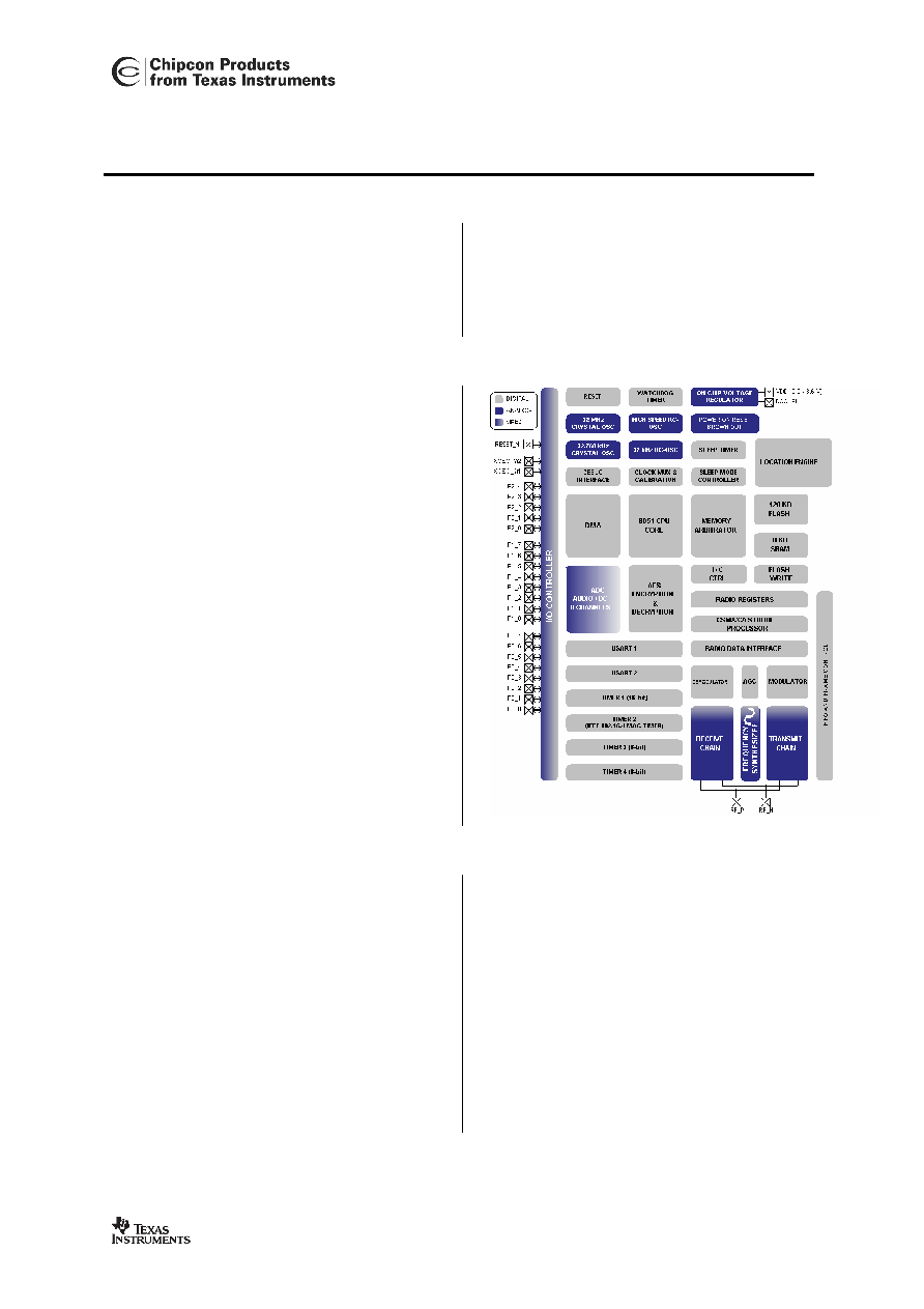
Product Description
The
CC2431 is a true System-On-Chip (SOC)
for wireless sensor networking ZigBeeTM /
802.15.4 solutions with location detection
engine hardware onboard allowing location
accuracy of around 3 meters or less. It
enables ZigBeeTM nodes to be built with very
low total bill-of-material costs. The
CC2431
combines the excellent performance of the
leading
CC2420 RF transceiver with an
industry-standard enhanced 8051 MCU, 128
KB flash memory, 8 KB RAM and many other
powerful features. Combined with the industry
leading ZigBeeTM protocol stack (Z-StackTM)
from Figure 8 Wireless / Chipcon, the
CC2431
provides the market's most competitive
ZigBeeTM solution.
The
CC2431 is highly suited for systems where
ultra low power consumption is required. This
is achieved by various operating modes. Short
transition times between these modes further
ensure low power consumption.
Key Features
· Location Engine accurately calculates
the location of a node in a network
· High performance and low power
8051 microcontroller core.
· 2.4 GHz IEEE 802.15.4 compliant RF
transceiver (industry leading
CC2420
radio core).
· Excellent receiver sensitivity and
robustness to interferers
· 128 KB in-system programmable flash
· 8 KB RAM, 4 KB with data retention in
all power modes
· Powerful DMA functionality
· Very few external components
· Only a single crystal needed for mesh
network systems
· Low current consumption (RX: 27mA,
TX: 25mA, microcontroller running at
32 MHz)
·
Only 0.9µA current consumption in
power-down mode, where external
interrupts or the RTC can wake up the
system
This data sheet contains preliminary data, and supplementary data will be published at a later date. Chipcon
reserves the right to make changes at any time without notice in order to improve design and supply the best
possible product. The product at this point is not fully qualified.

CC2431
CC2431 PRELIMINARY Datasheet (Rev. 1.01)
SWRS034A
Page 2 of 13
Key Features (continued)
· Less than 0.6µA current consumption
in power-down mode, where external
interrupts can wake up the system
· Very fast transition times from low-
power modes to active mode enables
ultra low average power consumption
in low duty-cycle systems
· CSMA/CA hardware support
· Wide supply voltage range (2.0V
3.6V)
· Digital RSSI/ LQI support
· Battery monitor and temperature
sensor
· 8-14 bits ADC with up to eight inputs
· 128-bit AES security coprocessor
· Two powerful USARTs with support
for several serial protocols.
· Hardware debug support
· Watchdog
timer
· One IEEE 802.15.4 MAC Timer, one
general 16-bit timer and two 8-bit
timers
· RoHS compliant 7x7mm QLP48
package
· 21 general I/O pins, two with 20mA
sink/source capability
·
Powerful and flexible development
tools available
Note:
The CC2431 and the CC2430 are pin compatible, and the MCU and RF parts of the
CC2430-F128 are identical to the CC2431 except the Location Engine. This data sheet
complements the CC2430 data sheet with a description of the Location Engine. For
complete information about the CC2431, please refer to the CC2430 data sheet in
addition to this data sheet.

CC2431
CC2431 PRELIMINARY Datasheet (Rev. 1.01) SWRS034A Page 3 of 13
Table Of Contents
1
REGISTER CONVENTIONS ................................................................................................................. 4
2
LOCATION ENGINE .............................................................................................................................. 5
2.1
L
OCATION
E
NGINE
O
PERATION
................................................................................................................... 5
2.2
L
OCATION
E
NGINE
R
EGISTERS
.................................................................................................................. 10
3
ORDERING INFORMATION .............................................................................................................. 12
4
GENERAL INFORMATION ................................................................................................................ 12
4.1
D
OCUMENT
H
ISTORY
................................................................................................................................. 12
4.2
P
RODUCT
S
TATUS
D
EFINITIONS
................................................................................................................. 12
4.3
D
ISCLAIMER
.............................................................................................................................................. 13
4.4
T
RADEMARKS
............................................................................................................................................ 13
4.5
L
IFE
S
UPPORT
P
OLICY
............................................................................................................................... 13

CC2431
CC2431 PRELIMINARY Datasheet (Rev. 1.01) SWRS034A Page 4 of 13
1 Register
conventions
Each RF register is described in a separate table. The table heading is given in the following
format:
REGISTER NAME (XDATA Address)
In the register descriptions, each register bit is shown with a symbol indicating the access
mode of the register bit. The register values are always given in binary notation unless
prefixed by `0x' which indicates hexadecimal notation.
Symbol
Access Mode
R/W Read/write
R Read
only
R0
Read as 0
R1
Read as 1
W Write
only
W0
Write as 0
W1
Write as 1
H0 Hardware
clear
H1 Hardware
set
Table 1: Register bit conventions

CC2431
CC2431 PRELIMINARY Datasheet (Rev. 1.01) SWRS034A Page 5 of 13
2 Location
Engine
The Location Engine is used to estimate
the position of nodes in an ad-hoc wireless
network. Reference nodes exist with
known coordinates, typically because they
are part of an installed infrastructure.
Other nodes are blind nodes, whose
coordinates need to be estimated. These
blind nodes are often mobile and attached
to assets that need to be tracked.
The Location Engine implements a
distributed computation algorithm that
uses received signal strength indicator
(RSSI) values from known reference
nodes, such as mobile neighbor nodes
with the same Location Engine, or fixed
infrastructure nodes. Performing location
calculations at the node level reduces
network traffic and communication delays
otherwise present in a centralized
computation approach.
The Location Engine has the following
main features:
· Three to eight reference nodes
can be used for the location
estimation algorithm
· Location estimate with resolution
of 0.5 meters
· Time to estimate node location
less than 40 µs
· Location range 64 x 64 meters
· Location error can be less than 3
meters, depending on factors
described below
· Runs location estimation with
minimum CPU usage
To achieve the best possible accuracy one
should use antennas that have near-
isotropic radiation characteristics. The
location error depends on signal
environment, deployment pattern of
reference nodes and the density of
reference nodes in a given area. In
general, having more reference nodes
available improves the accuracy of the
location estimation.
2.1 Location Engine Operation
This section describes the basic steps
required to obtain location estimates from
the Location Engine.
The Location Engine requires a set of
three to eight reference coordinates to be
input together with a set of measured
parameters. The output from the Location
Engine consists of a pair of estimated
location coordinates.
Before any input data is written, the
Location Engine must be enabled by
writing a 1 to the enable bit,
LOCENG.EN
.
When the Location Engine is not in use,
writing a 0 to
LOCENG.EN
will reduce the
power consumption of the CC2431 by
gating off the Engine's clock signal.
Figure 1 shows the basic operation of the
Location Engine.
Document Outline