MSP430x12x
MIXED SIGNAL MICROCONTROLLER
SLAS312A ≠ JULY 2001 ≠ REVISED MARCH 2003
1
POST OFFICE BOX 655303
∑
DALLAS, TEXAS 75265
D
Low Supply Voltage Range 1.8 V ≠ 3.6 V
D
Ultralow-Power Consumption:
≠ Active Mode: 200
µ
A at 1 MHz, 2.2 V
≠ Standby Mode: 0.7
µ
A
≠ Off Mode (RAM Retention): 0.1
µ
A
D
Five Power Saving Modes
D
Wake-Up From Standby Mode in 6
µ
s
D
16-Bit RISC Architecture, 125 ns
Instruction Cycle Time
D
Basic Clock Module Configurations:
≠ Various Internal Resistors
≠ Single External Resistor
≠ 32 kHz Crystal
≠ High Frequency Crystal
≠ Resonator
≠ External Clock Source
D
16-Bit Timer_A With Three
Capture/Compare Registers
D
On-Chip Comparator for Analog Signal
Compare Function or Slope A/D
Conversion
D
Serial Communication Interface (USART)
Software-Selects Asynchronous UART or
Synchronous SPI
D
Serial Onboard Programming,
No External Programming Voltage Needed
Programmable Code Protection by Security
Fuse
D
Family Members Include:
MSP430F122:
4KB + 256B Flash Memory
256B RAM
MSP430F123:
8KB + 256B Flash Memory
256B RAM
D
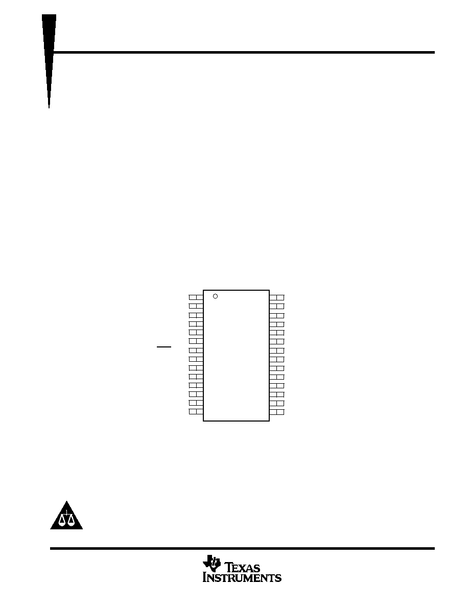
Available in a 28-Pin Plastic Small-Outline
Wide Body (SOWB) Package and 28-Pin
Plastic Thin Shrink Small-Outline Package
(TSSOP)
D
For Complete Module Descriptions, See the
MSP430x1xx Family User's Guide,
Literature Number SLAU049
1
2
3
4
5
6
7
8
9
10
11
12
13
14
28
27
26
25
24
23
22
21
20
19
18
17
16
15
TEST
V
CC
P2.5/R
osc
V
SS
XOUT
XIN
RST/NMI
P2.0/ACLK
P2.1/INCLK
P2.2/CAOUT/TAO
P3.0/STE0
P3.1/SIMO0
P3.2/SOMI0
P3.3/UCLK0
P1.7/TA2/TDO/TDI
P1.6/TA1/TDI
P1.5/TA0/TMS
P1.4/SMCLK/TCK
P1.3/TA2
P1.2/TA1
P1.1/TA0
P1.0/TACLK
P2.4/CA1/TA2
P2.3/CA0/TA1
P3.7
P3.6
P3.5/URXD0
P3.4/UTXD0
DW OR PW PACKAGE
(TOP VIEW)
description
The Texas Instruments MSP430 family of ultralow power microcontrollers consist of several devices featuring
different sets of peripherals targeted for various applications. The architecture, combined with five low power
modes is optimized to achieve extended battery life in portable measurement applications. The device features
a powerful 16-bit RISC CPU, 16-bit registers, and constant generators that attribute to maximum code efficiency.
The digitally controlled oscillator (DCO) allows wake-up from low-power modes to active mode in less than 6
µ
s.
Please be aware that an important notice concerning availability, standard warranty, and use in critical applications of
Texas Instruments semiconductor products and disclaimers thereto appears at the end of this data sheet.
Copyright
2001, ≠ 2003 Texas Instruments Incorporated
PRODUCTION DATA information is current as of publication date.
Products conform to specifications per the terms of Texas Instruments
standard warranty. Production processing does not necessarily include
testing of all parameters.
MSP430x12x
MIXED SIGNAL MICROCONTROLLER
SLAS312A ≠ JULY 2001 ≠ REVISED MARCH 2003
2
POST OFFICE BOX 655303
∑
DALLAS, TEXAS 75265
description (continued)
The MSP430F12x series is an ultralow-power mixed signal microcontroller with a built-in 16-bit timer and
twenty-two I/O pins.The MSP430F12x series also has a built-in communication capability using asynchronous
(UART) and synchronous (SPI) protocols in addition to a versatile analog comparator.
Typical applications include sensor systems that capture analog signals, convert them to digital values, and then
process the data and display them or transmit them to a host system. Stand alone RF sensor front end is another
area of application. The I/O port inputs provide single slope A/D conversion capability on resistive sensors.
AVAILABLE OPTIONS
PACKAGED DEVICES
TA
PLASTIC 28-PIN SOWB
(DW)
PLASTIC 28-PIN TSSOP
(PW)
∞
∞
MSP430F122IDW
MSP430F122IPW
≠ 40
∞
C to 85
∞
C
MSP430F122IDW
MSP430F123IDW
MSP430F122IPW
MSP430F123IPW
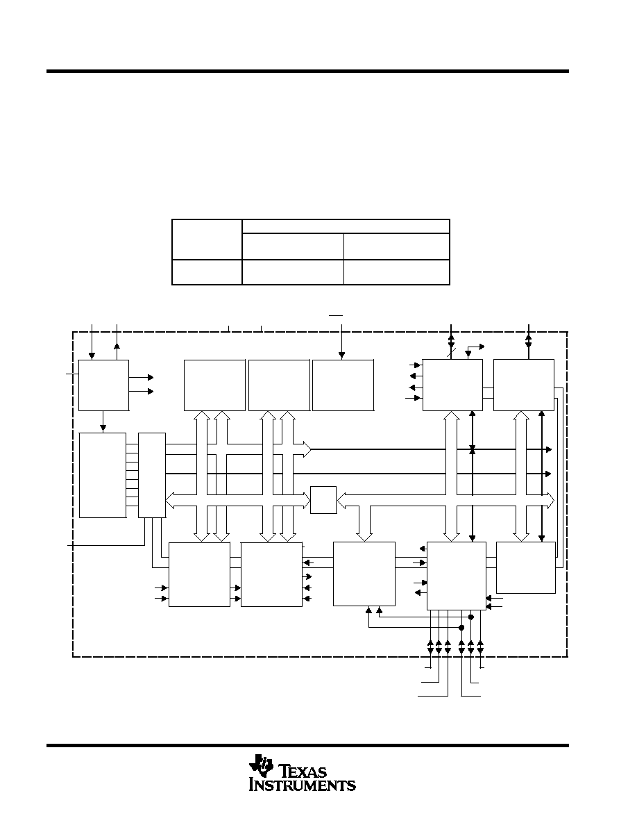
functional block diagram
ACLK
SMCLK
Power-on-
Reset
I/O Port P1
CPU
Incl. 16 Reg.
Test
JTAG
Bus
Conv
MAB,
MDB,
MAB, 4 Bit
MDB, 8 Bit
MCB
XIN
XOUT
VCC
VSS
RST/NMI
P1.0≠7
DCOR
ACLK
P2.0 / ACLK
Rosc
TEST
Outx
MCLK
ACLK
SMCLK
Outx
CCIx
CCIx
TACLK
INCLK
INCLK
Out0
CCI0
JTAG
CCIxA
TACLK
SMCLK
I/O Port P2
6 I/O's All With
8
Interrupt
Capabililty
Comparator_A
Input Multiplexer
RC Filtered O/P
Internal Vref
Analog Switch
P2.1 / INCLK
P2.2 / CAOUT/TA0
P2.5 / Rosc
P2.4 / CA1/TA2
P2.3 / CA0/TA1
CCI1
+ Flash INFO
4KB/8KB Flash
8 I/O's, All With
Interrupt
Capabililty
P1.0≠7
8
P3.0-7
I/O
Port P3
256B
RAM
Watchdog
Timer
15/16 Bit
or
CCI1
USART
UART
Mode
SPI
Mode
Timer_A
3 CC
CCR0/1/2
x = 0, 1, 2
Register
16 Bit
16 bit
Oscillator
System Clock
MSP430x12x
MIXED SIGNAL MICROCONTROLLER
SLAS312A ≠ JULY 2001 ≠ REVISED MARCH 2003
3
POST OFFICE BOX 655303
∑
DALLAS, TEXAS 75265
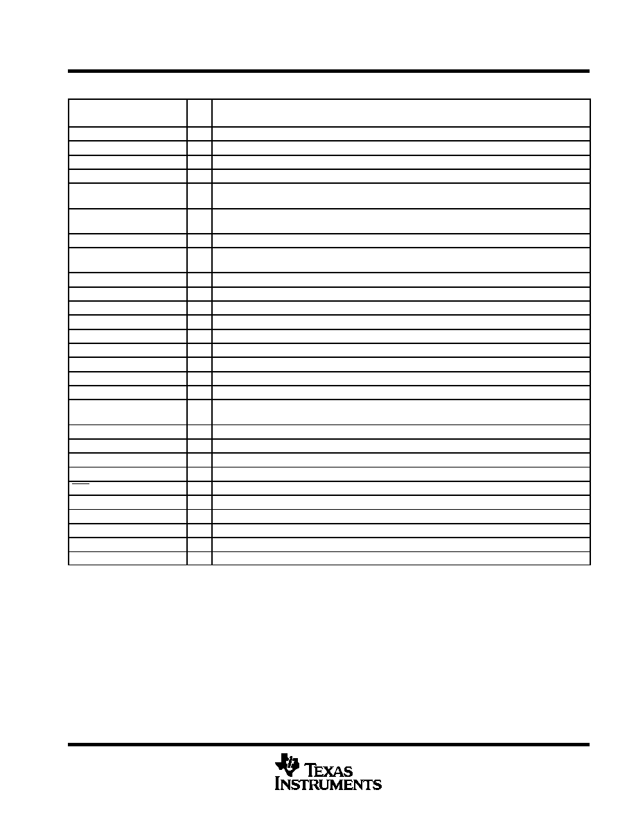
Terminal Functions
TERMINAL
NAME
NO.
I/O
DESCRIPTION
P1.0/TACLK
21
I/O
General-purpose digital I/O pin/Timer_A, clock signal TACLK input
P1.1/TA0
22
I/O
General-purpose digital I/O pin/Timer_A, capture: CCI0A input, compare: Out0 output
P1.2/TA1
23
I/O
General-purpose digital I/O pin/Timer_A, capture: CCI1A input, compare: Out1 output
P1.3/TA2
24
I/O
General-purpose digital I/O pin/Timer_A, capture: CCI2A input, compare: Out2 output
P1.4/SMCLK/TCK
25
I/O
General-purpose digital I/O pin/SMCLK signal output/test clock, input terminal for device programming
and test
P1.5/TA0/TMS
26
I/O
General-purpose digital I/O pin/Timer_A, compare: Out0 output/test mode select, input terminal for
device programming and test
P1.6/TA1/TDI
27
I/O
General-purpose digital I/O pin/Timer_A, compare: Out1 output/test data input terminal
P1.7/TA2/TDO/TDI
28
I/O
General-purpose digital I/O pin/Timer_A, compare: Out2 output/test data output terminal or data input
during programming
P2.0/ACLK
8
I/O
General-purpose digital I/O pin/ACLK output
P2.1/INCLK
9
I/O
General-purpose digital I/O pin/Timer_A, clock signal at INCLK
P2.2/CAOUT/TA0
10
I/O
General-purpose digital I/O pin/Timer_A, capture: CCI0B input/comparator_A, output
P2.3/CA0/TA1
19
I/O
General-purpose digital I/O pin/Timer_A, compare: Out1 output/comparator_A, input
P2.4/CA1/TA2
20
I/O
General-purpose digital I/O pin/Timer_A, compare: Out2 output/comparator_A, input
P2.5/Rosc
3
I/O
General-purpose digital I/O pin/Input for external resistor that defines the DCO nominal frequency
P3.0/STE0
11
I/O
General digital I/O, slave transmit enable--USART0/SPI mode
P3.1/SIMO0
12
I/O
General digital I/O, slave in/master out of USART0/SPI mode
P3.2/SOMI0
13
I/O
General digital I/O, slave out/master in of USART0/SPI mode
P3.3/UCLK0
14
I/O
General digital I/O, external clock input--USART0/UART or SPI mode, clock output--USART0/SPI
mode clock input
P3.4/UTXD0
15
I/O
General digital I/O, transmit data out--USART0/UART mode
P3.5/URXD0
16
I/O
General digital I/O, receive data in--USART0/UART mode
P3.6
17
I/O
General digital I/O
P3.7
18
I/O
General digital I/O
RST/NMI
7
I
Reset or nonmaskable interrupt input
TEST
1
I
Select of test mode for JTAG pins on Port1
VCC
2
Supply voltage
VSS
4
Ground reference
XIN
6
I
Input terminal of crystal oscillator
XOUT
5
I/O
Output terminal of crystal oscillator
TDO or TDI is selected via JTAG instruction.
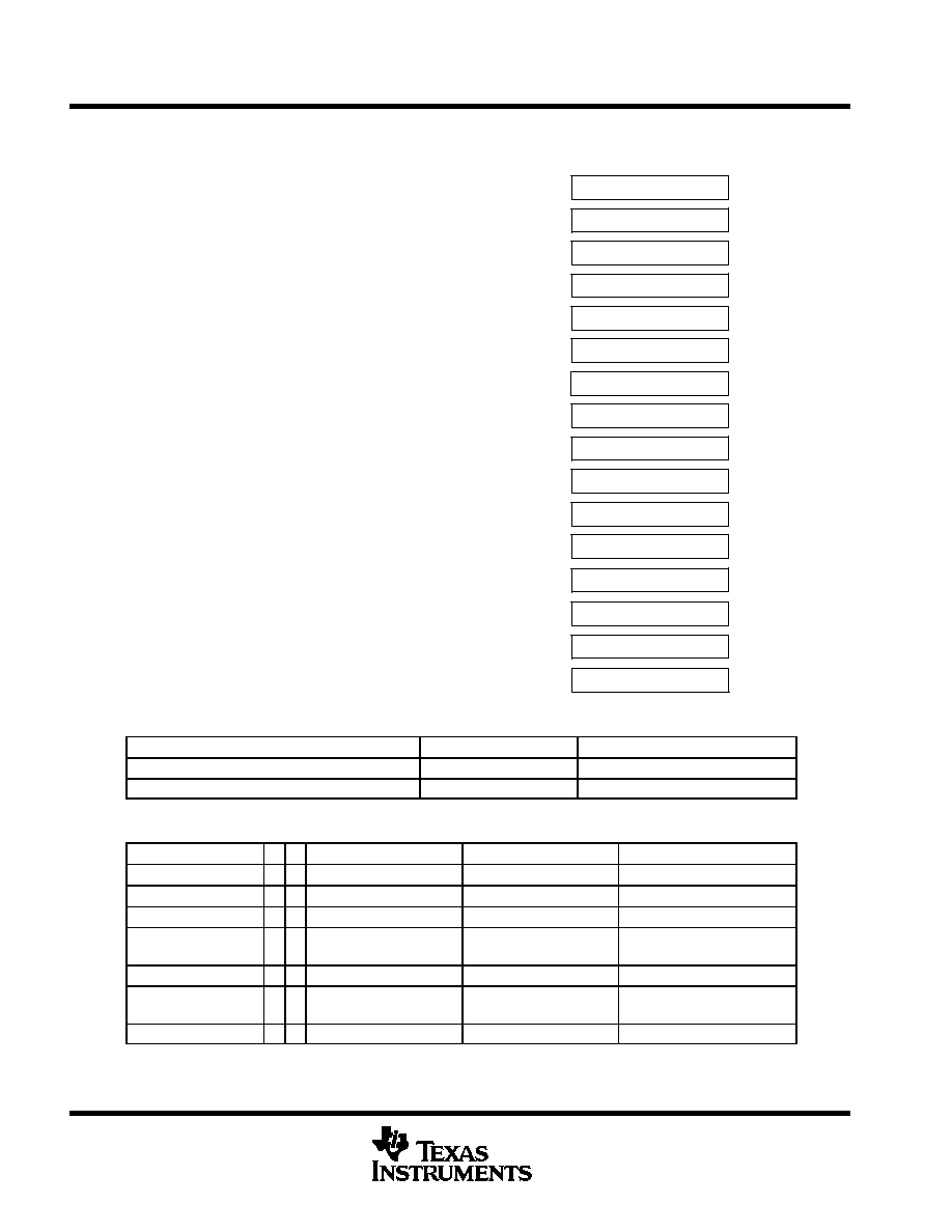
General-Purpose Register
Program Counter
Stack Pointer
Status Register
Constant Generator
General-Purpose Register
General-Purpose Register
General-Purpose Register
PC/R0
SP/R1
SR/CG1/R2
CG2/R3
R4
R5
R12
R13
General-Purpose Register
General-Purpose Register
R6
R7
General-Purpose Register
General-Purpose Register
R8
R9
General-Purpose Register
General-Purpose Register
R10
R11
General-Purpose Register
General-Purpose Register
R14
R15
MSP430x12x
MIXED SIGNAL MICROCONTROLLER
SLAS312A ≠ JULY 2001 ≠ REVISED MARCH 2003
4
POST OFFICE BOX 655303
∑
DALLAS, TEXAS 75265
short-form description
CPU
The MSP430 CPU has a 16-bit RISC architecture
that is highly transparent to the application. All
operations, other than program-flow instructions,
are performed as register operations in conjunc-
tion with seven addressing modes for source
operand and four addressing modes for destina-
tion operand.
The CPU is integrated with 16 registers that
provide reduced instruction execution time. The
register-to-register operation execution time is
one cycle of the CPU clock.
Four of the registers, R0 to R3, are dedicated as
program counter, stack pointer, status register,
and constant generator respectively. The remain-
ing registers are general-purpose registers.
Peripherals are connected to the CPU using data,
address, and control buses, and can be handled
with all instructions.
instruction set
The instruction set consists of 51 instructions with
three formats and seven address modes. Each
instruction can operate on word and byte data.
Table 1 shows examples of the three types of
instruction formats; the address modes are listed
in Table 2.
Table 1. Instruction Word Formats
Dual operands, source-destination
e.g. ADD R4,R5
R4 + R5 ≠≠≠> R5
Single operands, destination only
e.g. CALL R8
PC ≠≠>(TOS), R8≠≠> PC
Relative jump, un/conditional
e.g. JNE
Jump-on-equal bit = 0
Table 2. Address Mode Descriptions
ADDRESS MODE
S
D
SYNTAX
EXAMPLE
OPERATION
Register
n n
MOV Rs,Rd
MOV R10,R11
R10 ≠≠> R11
Indexed
n n
MOV X(Rn),Y(Rm)
MOV 2(R5),6(R6)
M(2+R5)≠≠> M(6+R6)
Symbolic (PC relative)
n n
MOV EDE,TONI
M(EDE) ≠≠> M(TONI)
Absolute
n n
MOV and MEM,and
TCDAT
M(MEM) ≠≠> M(TCDAT)
Indirect
n
MOV @Rn,Y(Rm)
MOV @R10,Tab(R6)
M(R10) ≠≠> M(Tab+R6)
Indirect
autoincrement
n
MOV @Rn+,Rm
MOV @R10+,R11
M(R10) ≠≠> R11
R10 + 2≠≠> R10
Immediate
n
MOV #X,TONI
MOV #45,TONI
#45 ≠≠> M(TONI)
NOTE: S = source D = destination

MSP430x12x
MIXED SIGNAL MICROCONTROLLER
SLAS312A ≠ JULY 2001 ≠ REVISED MARCH 2003
5
POST OFFICE BOX 655303
∑
DALLAS, TEXAS 75265
operating modes
The MSP430 has one active mode and five software selectable low-power modes of operation. An interrupt
event can wake up the device from any of the five low-power modes, service the request and restore back to
the low-power mode on return from the interrupt program.
The following six operating modes can be configured by software:
D
Active mode AM;
≠
All clocks are active
D
Low-power mode 0 (LPM0);
≠
CPU is disabled
ACLK and SMCLK remain active. MCLK is disabled
D
Low-power mode 1 (LPM1);
≠
CPU is disabled
ACLK and SMCLK remain active. MCLK is disabled
DCO's dc-generator is disabled if DCO not used in active mode
D
Low-power mode 2 (LPM2);
≠
CPU is disabled
MCLK and SMCLK are disabled
DCO's dc-generator remains enabled
ACLK remains active
D
Low-power mode 3 (LPM3);
≠
CPU is disabled
MCLK and SMCLK are disabled
DCO's dc-generator is disabled
ACLK remains active
D
Low-power mode 4 (LPM4);
≠
CPU is disabled
ACLK is disabled
MCLK and SMCLK are disabled
DCO's dc-generator is disabled
Crystal oscillator is stopped