
TFB2010
FUTUREBUS+ ARBITRATION BUS CONTROLLER
SLLS125A ≠ OCTOBER 1990 ≠ REVISED NOVEMBER 1993
POST OFFICE BOX 655303
∑
DALLAS, TEXAS 75265
Copyright
©
1993, Texas Instruments Incorporated
7≠1
∑
Supports Distributed Arbitration for
Futurebus+ Master Selection
∑
Supports Arbitrated Messages in
Distributed and Central Modes
∑
Enables Use of a Common Hardware and
Software Interface for Both Distributed and
Central Modes
∑
Requires No Hardware Modifications for
Changing Between Distributed and Central
Modes
∑
Provides a CSR Bus Interface for Easy
Integration into the Futurebus+ CSR
Address Space
∑
Has Two Bus Request Lines That Each May
Be Assigned Any One of 256 Priority Levels
∑
Supports Round-Robin Fairness Arbitration
Within Two Separate Priority Levels to
Avoid Starvation of Any Single Module
∑
Supports Distributed-Mode Bus Parking to
Improve Performance of Successive Bus
Acquisitions By a Single Module During
Idle Bus Conditions
∑
Offers Accurate Arbitration Settling Time
and Glitch Filter Programmability to Allow
Optimal Arbitration Bus Performance
∑
Provides a FIFO for Capturing up to Four
Incoming Arbitrated Messages
∑
Provides Hardware Support of Targeted
Interrupts
∑
Supports Power-Fail Message Indication
With a Separate Terminal and Interrupt
∑
Provides On-Chip Error Time-Out Detection
∑
Has a JTAG Test Port
description
The TFB2010 arbitration bus controller (ABC) is a member of the Texas Instruments Futurebus
+
chip set. This
chip set provides an integrated approach to the Futurebus
+
interface that reduces new-product design time,
allows more functionality per circuit board, improves overall interface reliability, and reduces end-user down time
through built-in test capabilities.
The TFB2010 performs the Futurebus
+
distributed-arbitration protocol to gain tenure of the bus (distributed
mode only), to send and receive arbitrated messages (central or distributed mode), and to update central-mode
arbiter priorities (central mode only).
The TFB2010 can be used in conjunction with a central-bus arbiter as an arbitrated-message controller to
program the central-bus arbiter, send asynchronous interrupts, or send event messages or interrupts to other
modules. In the case of a failure in the central-bus arbiter or if distributed arbitration is desired, it can be used
as a distributed-arbitration controller without a change in the host software. Priority changes are sent to the
central arbiter as arbitrated messages. This device monitors the bus for arbitration messages, storing these in
a FIFO or in the targeted interrupt register for reference by the processor. It also provides the necessary control
functions to gain control of the Futurebus
+
for a module attempting to perform a bus transaction when operating
in the distributed-arbitration mode.
The TFB2010 is offered in a 100-pin plastic quad flat package (PJM) to enhance interface capability. The
TFB2010 is characterized for operation over the commercial temperature range of 0
∞
C to 70
∞
C.
NOTE: To maintain consistency with the notation used in the Futurebus
+
standard (IEEE Std 896.1≠1991), an active low-signal is denoted herein
by use of the trailing asterisk (*) on the signal name.
PRODUCTION DATA information is current as of publication date.
Products conform to specifications per the terms of Texas Instruments
standard warranty. Production processing does not necessarily include
testing of all parameters.

TFB2010
FUTUREBUS+ ARBITRATION BUS CONTROLLER
SLLS125A ≠ OCTOBER 1990 ≠ REVISED NOVEMBER 1993
POST OFFICE BOX 655303
∑
DALLAS, TEXAS 75265
7≠2
terminal assignments
ARO
ARI
AQO
AQI
APO
API
OEA
CMPT*
LE*
WIN
GND
CNP
CN7
CN6
CN5
CN4
CN3
GND
CA9
CA8
CA7
CA6
GND
CA5
CA4
CA3
CA2
CA1
GND
CDP
CD7
CD6
CD5
CD4
81
82
83
84
85
86
87
88
89
90
91
92
93
94
95
96
97
98
99
100
50
49
48
47
46
45
44
43
42
41
40
39
38
37
36
35
34
33
32
31
CA10
CA11
GND
GA4*
GA3*
GA1*
GA0*
TMS
TCK
TDI
TDO
GND
CLK
GND
PFAIL*
INT*
REF
80
79
78
77
76
75
74
73
72
71
70
69
68
67
66
65
64
63
62
61
NC
ASI
REI
GND
ACI0
ACO1
ACI1
60
59
58
57
56
55
54
53
52
51
CD3
GND
CD2
CD1
CD0
COE*
CCE*
CWE*
GND
REFCLK
GND
RST*
SYSRESET*
BUSI*
ARBERR1
ARBERR0
GND
RQ1
RQ0
GR
PE
CENTMODE
CN0
CN1
CN2
GND
1
2
3
4
5
6
7
8
9
10
11
12
13
14
15
16
17
18
19
20
21
22
23
24
25
26
27
28
29
30
V
CC
CA0
V
CC
V
CC
V
CC
V
CC
V
CC
V
CC
V
CC
ACO0
V
CC
NC
V
CC
GA2*
BINIT*
V
CC
NC ≠ No internal connection
PJM . . . PACKAGE
(TOP VIEW)

TFB2010
FUTUREBUS+ ARBITRATION BUS CONTROLLER
SLLS125A ≠ OCTOBER 1990 ≠ REVISED NOVEMBER 1993
POST OFFICE BOX 655303
∑
DALLAS, TEXAS 75265
7≠3
Terminal Functions
CSR bus
TERMINAL
I/O
FROM/TO
DESCRIPTION
NAME
NO.
I/O
FROM/TO
DESCRIPTION
CA<11:0>
79,80,81,83,
84,85,87,88,
89,91,92,93
I
CSR bus
CSR bus address inputs
CCE*
8
I
CSR bus
CSR bus chip enable input
CD<7:0>
96,97,99,
100,1,3,4,5
I/O
CSR bus
CSR bus data
CDP
95
I/O
CSR bus
CSR bus data odd parity
COE*
7
I
CSR bus
CSR bus output enable input
CWE*
9
I
CSR bus
CSR bus write enable input
protocol controller interface
TERMINAL
I/O
FROM/TO
DESCRIPTION
NAME
NO.
I/O
FROM/TO
DESCRIPTION
ARBERR<1:0>
18,19
O
Arbitration error outputs:
LL
No error
LH
AC0 and AC1 asserted during phase 3
LH
AC0 and AC1 asserted during hase 3
HL
Arbitration comparison error or parity error
HH
Arbitration time-out error (phase 2 or 4)
GR
23
O
Futurebus + mastership has been granted output (bus tenure may begin). This signal remains
in the high-impedance state while in the central-bus arbitration mode.
PE
25
I/O
In distributed mode when this device is the bus master, the TFB2010 asserts PE to indicate
that a module with a higher priority has become the master elect. PE is released along with
GR when RQ1 and RQ0 are released. In central mode, the TFB2010 puts this output in a
high-impedance state to allow the central-arbitration controller to control preemption. PE is
monitored by the TFB2010 during a Futurebus + system reset to determine the system
operational mode (central or distributed) following the reset.
RQ<1:0>
21,22
I
Futurebus + mastership is requested in centralized mode input:
RQ0 asserted:
use arbitration number in the RQ0 priority register
RQ0 asserted:
use arbitration number in the RQ0 riority register
RQ1 asserted:
use arbitration number in the RQ1 priority register
Once a request is asserted, it is not released until GR* has been asserted (the TI protocol
controllers perform this handshake internally). Once GR* is asserted, RQn* may be released
at any time after AS has been asserted by the module in the last bus transaction (AS may
already be released if no further transactions are to take place). Both request lines must be
released prior to release of GR*. Another RQn* can be asserted after GR* and PE have been
released.

TFB2010
FUTUREBUS+ ARBITRATION BUS CONTROLLER
SLLS125A ≠ OCTOBER 1990 ≠ REVISED NOVEMBER 1993
POST OFFICE BOX 655303
∑
DALLAS, TEXAS 75265
7≠4
Terminal Functions
other module interfaces
TERMINAL
I/O
FROM/TO
DESCRIPTION
NAME
NO.
I/O
FROM/TO
DESCRIPTION
CLK
65
I
Clock input. CLK is used by the CSR bus master(s).
INT*
62
O
(open-collector)
Host interrupt output. When an enabled interrupt condition occurs, INT is driven low.
Interrupts are cleared by writing a zero to the appropriate bit in the interrupt register. The
interrupt goes high during the write cycle to the interrupt register even if another interrupt
is pending.
PFAIL*
63
O
Power-fail message received output
REFCLK
11
I
Module
Clock input. The recommended frequency and duty cycle are 33 MHz, 50%
±
5%;
25 MHz to 33 MHz and 50%
±
5% can be tolerated.
JTAG test port
TERMINAL
I/O
FROM/TO
DESCRIPTION
NAME
NO.
I/O
FROM/TO
DESCRIPTION
TCK
70
I
Module
JTAG test clock input
TDI
69
I
Module
JTAG test data input
TDO
68
O
Module
JTAG test data output
TMS
71
I
Module
JTAG test mode select input
reset port
TERMINAL
I/O
FROM/TO
DESCRIPTION
NAME
NO.
I/O
FROM/TO
DESCRIPTION
BINIT*
14
I
Module
Bus interface reset input. BINIT is an open-collector signal indicating that a bus interface
reset is required
BUSI*
17
I
Bus has been idle for longer than 1
µ
s, and reset is asserted by this module.
REF
61
O
Futurebus+ reset filtered output
REI
57
I
Futurebus+ reset input
RST*
13
I
Module
Module power-up reset input. RST resets all logic; output signals go to their inactive states;
3-state outputs and bidirectionals go to the high-impedance state (for live-insertion
considerations).
SYSRESET*
15
I
Module
System reset input. SYSRESET* signal indicates that a system reset is required.
TFB2010
FUTUREBUS+ ARBITRATION BUS CONTROLLER
SLLS125A ≠ OCTOBER 1990 ≠ REVISED NOVEMBER 1993
POST OFFICE BOX 655303
∑
DALLAS, TEXAS 75265
7≠5
Terminal Functions
Futurebus
+
interface
TERMINAL
I/O
DESCRIPTION
NAME
NO.
I/O
DESCRIPTION
ACI<1:0>
52,54
I
Futurebus+ arbitration condition input
ACO<1:0>
53,55
O
Futurebus+ arbitration condition output
API, AQI, ARI
44,47,49
I
Futurebus+ arbitration handshake input
APO, AQO, ARO
45,48,50
O
Futurebus+ arbitration handshake output
ASI
58
I
Futurebus+ address handshake input
CENTMODE
26
O
Central-mode operation is in effect output
CMPT*
41
O
Arbitration contest logic compete indication output. Connects to COMPETE and OEB on the
competition transceiver.
CN<7:0>, CNP
36,35,33,32,31,
29,28,27,37
I/O
Futurebus+ contest number and parity
GA<4:0>*
77,76,75,74,73
I
Futurebus+ geographical address input
LE*
40
O
Enable latch on competition transceiver output (1 = competition number latched)
OEA
43
O
Enable TTL drivers on competition transceiver output
WIN
39
I
Arbitration contest logic win indication input
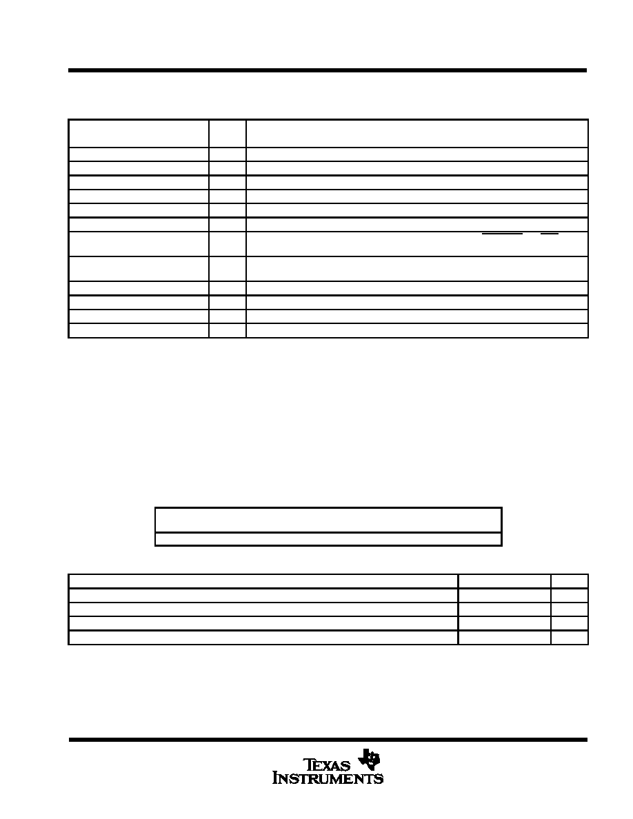
absolute maximum ratings over operating free-air temperature range (unless otherwise noted)
Supply voltage range, V
CC
(see Note 1)
≠ 0.5 V to 7 V
. . . . . . . . . . . . . . . . . . . . . . . . . . . . . . . . . . . . . . . . . . . . . .
Input voltage range, V
I
≠ 0.5 V to 7 V
. . . . . . . . . . . . . . . . . . . . . . . . . . . . . . . . . . . . . . . . . . . . . . . . . . . . . . . . . . . . . .
Output voltage range, V
O
≠ 0.5 V to 7 V
. . . . . . . . . . . . . . . . . . . . . . . . . . . . . . . . . . . . . . . . . . . . . . . . . . . . . . . . . . .
Continuous total power dissipation
See Dissipation Rating Table
. . . . . . . . . . . . . . . . . . . . . . . . . . . . . . . . . . . . .
Power dissipation
500 mW
. . . . . . . . . . . . . . . . . . . . . . . . . . . . . . . . . . . . . . . . . . . . . . . . . . . . . . . . . . . . . . . . . . . . . .
Operating free-air temperature range, T
A
0
∞
C to 70
∞
C
. . . . . . . . . . . . . . . . . . . . . . . . . . . . . . . . . . . . . . . . . . . . . .
Storage temperature range
≠ 65
∞
C to 150
∞
C
. . . . . . . . . . . . . . . . . . . . . . . . . . . . . . . . . . . . . . . . . . . . . . . . . . . . . . .
Case temperature for 10 seconds
260
∞
C
. . . . . . . . . . . . . . . . . . . . . . . . . . . . . . . . . . . . . . . . . . . . . . . . . . . . . . . . . .
NOTE 1: All voltage values are with respect to GND.
DISSIPATION RATING TABLE
PACKAGE
TA
25
∞
C
POWER RATING
DERATING FACTOR
ABOVE TA = 25
∞
C
TA = 70
∞
C
POWER RATING
PJM
1500 mW
12 mW/
∞
C
960 mW
recommended operating conditions
MIN
NOM
MAX
UNIT
Supply voltage, VCC
4.75
5
5.25
V
High-level input voltage, VIH
2
VCC
V
Low-level input voltage, VIL
≠ 0.5
0.8
V
Operating free-air temperature range, TA
0
70
∞
C