 | –≠–ª–µ–∫—Ç—Ä–æ–Ω–Ω—ã–π –∫–æ–º–ø–æ–Ω–µ–Ω—Ç: UC3638N | –°–∫–∞—á–∞—Ç—å:  PDF PDF  ZIP ZIP |

UC2638
UC3638
SLUS290A - JANUARY 1998 - REVISED JANUARY 2003
BLOCK DIAGRAM
∑
Single or Dual Supply Operation
∑
Accurate High Speed Oscillator
∑
Differential X5 Current Sense
Amplifier
∑
Bidirectional Pulse-by-Pulse
Current Limiting
∑
Programmable Oscillator
Amplitude and PWM Deadband
∑
Dual 500mA Totem Pole Output
Drivers
∑
Dual 60V, 50mA Open Collector
Drivers
∑
Undervoltage Lockout
Advanced PWM Motor Controller
FEATURES
DESCRIPTION
UDG-95048-4
The UC2638 family of integrated circuits are advanced pulse width modula-
tors intended for a variety of PWM motor drive and amplifier applications re-
quiring either uni-directional or bi-directional drive circuits. Similar in
architecture to the UC2637, all necessary circuitry is included to generate an
analog error signal and modulate two bi-directional pulse train outputs in pro-
portion to the error signal magnitude and polarity.
Key features of the UC2638 include a programmable high speed triangle os-
cillator, a 5X differential current sensing amplifier, a high slew rate error am-
plifier, high speed PWM comparators, and two 50mA open collector as well
as two
±
500mA totem pole output stages. The individual circuit blocks are
designed to provide practical operation to switching frequencies of 500kHz.
Significant improvements in circuit speed, elimination of many external pro-
gramming components, and the inclusion of a differential current sense am-
plifier, allow this controller to be specified for higher performance
applications, yet maintain the flexibility of the UC2637. The current sense
amplifier in conjunction with the error amplifier can be configured for average
current feedback. The additional open collector outputs provide a drive signal
continued
application
INFO
available
2
UC2638
UC3638
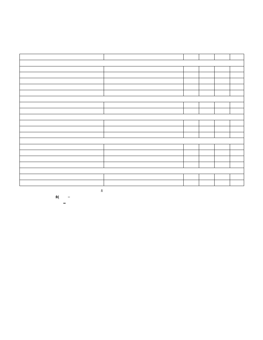
ABSOLUTE MAXIMUM RATINGS
for the highside switches in a full bridge configuration.
The programmable AREFIN pin allows for single or dual
supply operation. Oscillator ramp amplitude and PWM
deadband are programmable by tapping a voltage di-
vider off the 5V reference to the appropriate program-
ming input (PVSET or DB).
Additional features include a precision externally avail-
able 5V reference, undervoltage lockout, pulse-by-pulse
peak current limiting, and a remote shutdown port. The
UC1638 family is available in the 20 pin N, DW and J
packages. Consult the factory for other packaging op-
tions.
Supply Voltage VCC (referenced to VEE) . . . . . . . . . . . . . 40V
Output Drivers (AOUT2, BOUT2)
Currents (continuous) . . . . . . . . . . . . . . . . . . . . . . . .
±
0.25A
Currents (peak) . . . . . . . . . . . . . . . . . . . . . . . . . . . .
±
500mA
REF Output Current . . . . . . . . . . . . . . . . . . . . Internally Limited
PVSET, DB, RT, INV, REF, CSOUT . . . . . . . . . . . . . 0.3 to 10V
CS+, CS- . . . . . . . . . . . . . . . . . . . . . . . . . . . . . VEE≠1V to VCC
CT, AREF, AREFIN, COMP, SD . . . . . . . . . . . . . . . . VEE
-
0.3
Output Voltage (AOUT1, BOUT1) . . . . . . . . . . . . . . . . . . . . 60V
Storage temperature . . . . . . . . . . . . . . . . . . . .
-
65∞C to +150∞C
Junction Temperature . . . . . . . . . . . . . . . . . . .
-
55∞C to +150∞C
Lead temperature (soldering, 10 sec.) . . . . . . . . . . . . . . +300∞C
Currents are positive into, negative out of the specified termi-
nal. Consult packaging section of data book for thermal limita-
tion considerations of packages.
DESCRIPTION (cont.)
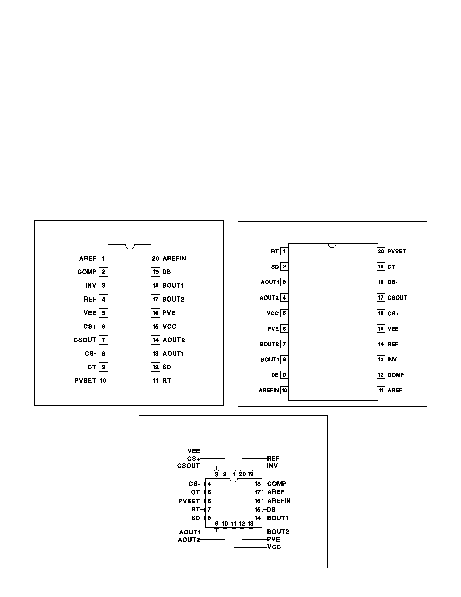
CONNECTION DIAGRAMS
DIL-20 (Top View)
N Package
SOIC-20 (Top View)
DW Package
PLCC-20 (Top View)
Q Package

3
UC2638
UC3638
ELECTRICAL CHARACTERISTICS
Unless otherwise specified; VCC = 15V, VEE =≠15V, CT = 680pF, RT = 3k,
V
PVSET
= 1.5V, V
COMP
= 0V, V
CSOUT
= 0V, V
DB
= REF, V
EXTREF
= 0V, V
SD
=
VCC ≠ 3V, T
A
=
-
25∞C to 85∞C for the UC2638, 0∞C to 70∞C for the UC3638,
T
A
= T
J
.
PARAMETER
TEST CONDITIONS
MIN
TYP
MAX
UNITS
Overall
Supply Current, Operating
15
23
mA
UVLO Threshold
Reference to VEE
9
10
V
UVLO Hysteresis
Reference to VEE
1
V
Voltage Amplifier
Input Offset Voltage COMP = 0V
-20 0 20 mV
V
SENSE
Bias Current
0
0.5
2
A
Open Loop Gain
COMP =
-
5V to +5V
75
100
dB
CMRR
V
CM
=
-
5V to +5V
70
100
dB
PSRR
VCM = 0V, VCC
-
VEE = 10V to 36V
70
90
dB
V
OUT
High
INV =
-
0.1V, RL = 10k
13
13.6
V
V
OUT
Low
INV = +0.1V, RL = 10k
-
13.8
≠13
V
Slew Rate Rising and Falling
Overdrive =
±
1V
12
V/
µ
s
Output Source Current
COMP Shorted to VEE
5
15
mA
Output Sink Current
COMP Shorted to VCC
15
40
mA
Gain Bandwidth Product
F
IN
= 100kHz, 10mV p-p
1
5
MHz
5V Reference
Output Voltage
I
REF
=
-
1mA, T
A
= 25∞C
4.925
5
5.075
V
Output Voltage
I
REF
=
-
1mA
4.875
5
5.125
V
Load Regulation
I
REF
=
-
1mA to
-
10mA
-
15
2
15
mV
Line Regulation
VCC - VEE = 10V to 36V
-
15
2
15
mV
Short Circuit Current
V
REF
= 0V
15
70
mA
Oscillator
Initial Accuracy
T
A
= 0∞C ≠ 70∞C
86
98
110
kHz
Voltage Stability
VCC
-
VEE = 10V to 36V
2
%
Total Variation
Line, Temperature
76
98
120
kHz
PVSET Input Bias Current
0.5
3
µ
A
PVSET Input Voltage Range
(Note 1)
0.5
VREF
V
Amplitude Limit
(Note 1)
VEE+3
VCC
-
3
V
AOUT1, BOUT1 Output Drivers
Output Low Voltage
I
OUT
= 1mA, Ref. to PVE, PVE = 0V
0.9
1.3
V
I
OUT
= 50mA
1.2
1.8
V
Leakage Current
Output Voltage = 50V
0.1
50
µ
A
AOUT2, BOUT2 Output Drivers
Output High Voltage
I
OUT
=
-
20mA, Ref. to PVE, PVE = 0V
12.2
13.5
V
I
OUT
=
-
100mA, Ref. to PVE, PVE = 0V
12
13.5
V
Output High Clamp Level
I
OUT
=
-
20mA, Ref. to PVE, PVE = VEE
14.4
16.5
V
Output Low Voltage
I
OUT
= 20mA, Ref. to PVE, PVE = 0V
0.4
1
V
I
OUT
= 100mA, Ref. to PVE, PVE = 0V
0.6
2.2
V
Output Rise Time
C
OUT
= 1nF
50
100
ns
Output Fall Time
C
OUT
= 1nF
50
100
ns
4
UC2638
UC3638
Note 1: Oscillator triangle amplitude = 2.5 ∑ PV AREF.
Note 2: Deadband =
REF
DB), referenced to COMP.
Note 3: Offset = AREFIN
AREF.
AOUT1, BOUT1: AOUT1 and BOUT1 are open collector
output drivers capable of sinking 50mA. These outputs
can be pulled up to 60V maximum. With a few external
components, these outputs can drive the opposite high
side switches in a full bridge arrangement.
AOUT2, BOUT2: AOUT2 and BOUT2 are totem pole
output drivers capable of driving external power MOS-
FETs directly. The peak current ratings are
±
500mA. An
integrated zener clamp limits the drive output amplitude
to approximately 14V to prevent MOSFET gate oxide
overstress. These outputs are configured to drive the
opposite low side switches in a full bridge arrangement.
AREF: The voltage on AREF is simply a buffered ver-
sion of the voltage on AREFIN. In single supply applica-
tions, AREF should be bypassed to VEE with a 0.1
µ
F
ceramic capacitor to provide a stable reference level for
the internal circuitry.
AREFIN: The voltage on AREFIN is generated inter-
nally by a 50% voltage divider tied between VCC and
VEE. As such, it provides the mid supply reference
needed for the oscillator, voltage amplifier, current am-
plifier and current limit comparators when operating in
single supply mode. A buffer amplifier is connected be-
tween AREFIN and AREF. In bipolar supply applications
AREFIN is usually connected to VEE, which disables
the buffer amplifier, and AREF is connected to 0V.
COMP: This is the output of the high slew rate error am-
plifier. The level on COMP modulates the controller duty
cycle via the PWM comparators and the oscillator ramp.
Compensation and DC gain setting resistors are con-
nected between COMP and INV.
CS-: This is the inverting input to the X5 current sense
amplifier. The common mode input range for this pin ex-
tends from VEE
-
1V to VCC
-
4V. A low value resistor in
PIN DESCRIPTIONS
ELECTRICAL CHARACTERISTICS
Unless otherwise specified; VCC = 15V, VEE =≠15V, CT = 680pF, RT = 3k,
V
PVSET
= 1.5V, V
COMP
= 0V, V
CSOUT
= 0V, V
DB
= REF, V
EXTREF
= 0V, V
SD
=
VCC ≠ 3V, T
A
=
-
25∞C to 85∞C for the UC2638, 0∞C to 70∞C for the UC3638.
T
A
= T
J
.
PARAMETER
TEST CONDITIONS
MIN
TYP
MAX
UNITS
X5 Amplifier
Gain
V
ID
= 100mV to 400mV
4.75
5
5.25
V/V
Common Mode Rejection
V
CS+
, V
CS
-
= AREF
±
5V
50
65
dB
-
3dB Bandwidth
300
400
kHz
Slew Rate Rising
.75
1.5
V/
µ
s
Slew Rate Falling
.75
1.5
V/
µ
s
Shutdown
Threshold
Ref. to VCC
-
1.9
-
2.25
-
2.5
V
Input Bias Current
V
SD
= SD Threshold
-
0.5
-
10
µ
A
Current Limit
Threshold Positive
Measured Between CS+ and CS-
400
500
600
mV
Threshold Negative
Measured Between CS+ and CS-
≠ 600
-
500
≠ 400
mV
Propagation Delay to Outputs
Overdrive = 200mV
150
250
ns
Deadband Adjust
Maximum Deadband
V
DB
= 0V
±
5
V
Zero Deadband
V
DB
= REF
0
V
Deadband Adjustment Gain
V
DB
= 1V to 4V (Note 2)
±
0.9
±
1
±
1.2
V/V
Input Bias Current
V
DB
= VREF
3
15
µ
A
AREF Buffer
Gain
AREF / VCC
-
VEE
0.49
0.5
0.51
V/V
Offset
(Note 3)
30
100
mV
(continued)

5
UC2638
UC3638
PIN DESCRIPTIONS (cont.)
series with the source or emitter of the low side switch
in the full bridge develops the signal that is applied to
this pin. At differential inputs of
±
500mV typical (refer-
enced to CS+)the controller reaches the current limit
level, which truncates the output pulse.
CS+: This is the non-inverting input to the X5 current
sense amplifier. The common mode input range for this
pin extends from VEE
-
1V to VCC
-
4V. The characteris-
tics for this pin are identical to CS-.
CSOUT: This is the output of the X5 current sense am-
plifier. Voltage levels greater than
±
2.5V referenced to
AREF will cause the device to enter current limit. An in-
ternal 100 ohm resistor between the amplifier output
and CSOUT is provided to create a high frequency
noise filter with an external capacitor to VEE. When
used for average current feedback, CSOUT is summed
into INV.
CT: A capacitor from CT to VEE will set the triangle os-
cillator frequency according to the following equation:
F
1
5 RT CT
=
∑
∑
The waveform on CT is symmetrical about the voltage
on AREF and is applied internally to the inputs of hte
PWM comparators. Use a high quality ceramic capacitor
with low ESL and ESR for best results. A minimum CT
value of 200 pF insures good accuracy and less suscep-
tibility to circuit layout parasitics. The oscilator and PWM
are designed to provide practical operation to 500kHz.
DB: This high impedance input programs output pulse
train deadtime. A stable DC voltage between 0V and
REF will set a bi-directional deadband centered about
the level on COMP. The deadband level is equal to: 5V
-
VDB. That is, 1V on DB will program
±
4V of deadband
centered about the COMP pin level. A convenient
method for generating the programming level is a volt-
age divider tap off of REF.
INV: This is the inverting input to the Voltage amplifier.
The common mode input range for this pin extends from
VEE+2V to VCC
-
1V. It can be tied to a command signal
generated by a rate feedback element or to a position
control signal. In average current feedback applications,
this input is tied to the output of the X5 current sensing
amplifier (CSOUT).
PVE: This is the high current ground for the IC. The ex-
ternal MOSFET driver transistors are referenced to this
ground. Internal level shifting circuitry gives the option
of tying this pin to VEE, or the system ground in split
supply applications.
PVSET: A DC voltage on PVSET programs the upper
and lower thresholds for the oscillator by the following
relationship:
V
PK
-
V
VLY
= 5 ∑ V
PVSET
.
The input voltage range on PVSET is 0.5V to REF.
REF: REF is the output of the precision reference. The
output is capable of supplying 15mA to peripheral cir-
cuitry and is internally short circuit current limited. By-
pass REF to VEE with a 0.1
µ
F ceramic capacitor for
best performance.
RT: A single resistor from RT to VEE sets the charging
and discharging currents for the triangle oscillator. The
actual charge and discharge is 2X the current pro-
grammed by RT and PVSET. For best performance the
current out of RT should be limited to 1mA. The voltage
level on the RT pin is a buffered version of the PVSET
pin voltage. Therefore, if the PVSET voltage divider is
tied between VCC and VEE to incorporate line feedfor-
ward, the triangle waveform frequency will remain con-
stant.
SD: A voltage on SD within 2.5V (typical) of VCC will
cause the UC3638 to enter a UVLO condition which dis-
ables all of the driver outputs. With an external voltage
divider across VCC and VEE, and a capacitor between
SD and VCC, a delayed turn-on characteristic can be
generated. Since the 2.5V threshold is temperature sta-
bilized it can also be used as a higher UVLO threshold
for applications which require a starting voltage higher
than the internal 9V UVLO threshold.
VEE: All voltages are measured with respect to this pin.
All bypass capacitors and timing components except
those listed under the PVE section should be connected
to this pin. Component leads should be as short and di-
rect as possible. VEE is generally connected to the most
negative voltage supply in the system. In single supply
applications, VEE is tied to the system ground.
VCC: Positive supply rail for the IC. Bypass this pin to
VEE and PVE with 0.1 to 1
µ
F low ESL, ESR ceramic
capacitor(s). The maximum voltage for VCC is 40V ref-
erenced to VEE. The turn on voltage level on VCC is 9V
with 1V of hysteresis.
6
UC2638
UC3638
The UC3638 is designed to provide pulse width modula-
tion control of DC brush motors in applications requiring
precision torque, velocity, or position control. Due to its
high frequency capability, other high power applications
such as switch mode audio amplifiers can also be ad-
dressed. Through a combination of circuit sophistication
and integration, the designer can maintain a high level
of flexibility, while reducing cost compared to solutions
using other PWM ICs.
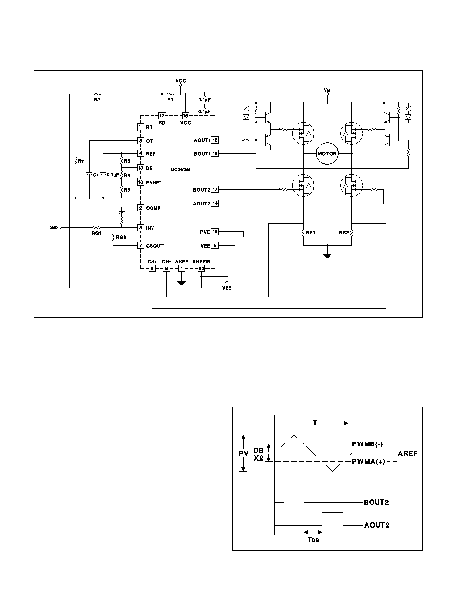
Figure 1 shows a typical application circuit for the
UC3638. By taking advantage of the UC3638's many in-
tegrated functions, a low cost and compact average cur-
rent mode motor controller can be designed. Depending
on the level of complexity, as many as 15 discrete com-
ponents and an additional high bandwidth amplifier can
be saved compared to a similar circuit using the
UC3637 PWM controller.
Oscillator Section and Modulation Scheme
Figure 2 depicts the UC3638 oscillator and PWM wave-
forms for the condition where the output of the voltage
amplifier (COMP) is at the null point (same voltage as
AREF). For applications using split voltage supply rails,
AREF will normally be tied to system ground. This re-
sults in a voltage null point of zero volts. For this condi-
tion, AREFIN should be tied to the negative voltage sup-
ply rail (VEE), which disables the internal voltage buffer,
allowing AREF to be tied to ground. For a single supply
system, AREFIN should be left open circuit, and AREF
should be decoupled to VEE (system ground) with at
least 0.1
µ
F. The resulting voltage null point for this case
APPLICATION INFORMATION
Figure 1. Average Motor Current Control Loop
UDG-95049-2
Figure 2. Oscillator and PWM Waveforms
UDG-95068-1

7
UC2638
UC3638
APPLICATION INFORMATION (cont.)
will be half way between ground and VCC, and will auto-
matically track changes in VCC. For cases where a dif-
ferent null point is desired, AREF can be tied to any
voltage between VEE + 2V and VCC
-
2V. Of course
the user must also allow sufficient headroom for the tri-
angle waveform.
Once the system null point has been chosen, the trian-
gle wave amplitude and PWM deadband must be pro-
grammed. The amplitude of the triangle wave is
determined by trading off noise immunity and gain re-
quirements. In general, the larger the triangle wave am-
plitude,
the
greater
the
immunity
to
premature
termination of PWM pulses due to switching noise. How-
ever, high amplitude triangle waves require a greater
voltage swing at the output of the voltage amplifier
which ultimately reduces forward loop gain.
Programming the PWM deadband allows the user to
trade off gain linearity requirements with power amplifier
efficiency. If the modulator is configured as in Figure 1,
motor current is alternately pulsed by diagonally oppo-
site drive FETs when the servo loop is at null. By adjust-
ing the deadband, the user can program the offset
voltage at the input of the PWM comparators. This offset
results in deadtime, or time when neither PWM signal is
active.
A minimum amount of deadtime is always recom-
mended to provide cross conduction protection at the
power amplifier. Setting the deadtime to this minimum
level will provide the maximum motor stiffness or holding
torque, at the expense of power losses in the output
stage. These losses result from the fact that the power
amplifier is always sourcing motor current, even at null.
As deadtime is increased, amplifier losses at null be-
come less, at the expense of nonlinearity in the gain
function. Eventually, if the deadband voltage is in-
creased to equal the amplitude of the triangle wave, er-
ror voltages at the null point will result in no PWM
pulsing, or a dead zone. After the triangle waveform am-
plitude and deadband are selected, the operating fre-
quency is easily set by proper selection of CT and RT.
Referring to Figure 1, if the voltage supply rails are
±
15V, and the desired triangle wave oscillator amplitude
is 6V p-p, PVSET is set by:
V
PK
-
V
VLY
= 5 ∑ V
PVSET
V
PVSET
=
6
5
= 1.2V
If 1V of deadband is chosen:
5
-
V
DB
= 1V
V
DB
= 4V
In order to select the programming resistors, a source
current for the reference is first selected. For a 1mA
source current:
R3 + R4 + R5 =
5
ISOURCE
=
5
1mA
= 5k
R3 =
5 - VDB
ISOURCE
=
1V
1mA
= 1k
R4 =
VDB - VPVSET
ISOURCE
=
4V - 1.2V
1mA
= 2.8k
R5 = 5k
-
1k
-
2.8k = 1.2k
All of the voltages described by these equations are ref-
erenced to the negative supply rail. In other words, for a
split supply system, VREF is actually a negative voltage
referenced to ground.
The oscillator frequency is programmed by proper se-
lection of RT and CT. If 220pF is chosen for CT, and an
operating frequency of 30kHz is desired, RT is chosen
by:
F =
1
5 RT CT
∑
∑
30kHz =
1
5
220pF RT
∑
∑
RT = 30k
With RT = 30k, the charge current out of the RT pin is
limited to
1.2V
30k
= 40
µ
A,
which is well within the specified maximum of 1mA.
To calculate the actual deadtime or minimum time be-
tween PWM pulses (T
DB
), the ratio of the deadband
voltage to the triangle wave amplitude is multiplied by
half the oscillator period:
T
DB
=
DB
VPK - VVLY
1
f
∑
=
5 - VDB
5
VPVSET
(5 RT CT)
∑
∑ ∑
∑
=
(5 - VDB) RT CT
VPVSET
∑
∑
For this example the deadtime is:
T
DB
=
1 30k
220pF
1.2
∑
∑
= 5.5
µ
sec
If voltage feedforward is desired, PVSET should be de-
rived off of the supply rails instead of VREF. This way
changes in the supply voltage will linearly regulate the
modulator gain, which decreases control loop suscepti-
bility to line voltage variations. Since the voltage on the
RT pin is a buffered version of PVSET, charge current
tracks oscillator amplitude, and therefore the frequency

8
UC2638
UC3638
remains constant, preventing low frequency oscillator
modulation in the presence of line voltage changes.
Output Drivers
The output driver section provides separate output driv-
ers for high and low side drive of both PWM signals. For
many applications, the 500mA peak output current ca-
pability of the low side drivers (AOUT2 and BOUT2) is
sufficient to directly connect to the appropriate low side
MOSFETs of the H-bridge. A current limiting gate resis-
tor may be used to control switching time if high levels of
dv/dt or di/dt are expected at the drains of the MOS-
FETs. If more current drive capability is required, the
PWM drive signals can be buffered with bipolar transis-
tors.
The open collector high side drivers (AOUT1 and
BOUT1) are designed to control high side P-channel
MOSFETs. Depending on voltage and speed require-
ments, the driver stage can be simplified from the one
shown on Figure 1. If high side N-channel MOSFETs
are desired, a boot strap or charge pump based drive
circuit can be used as long as 100% duty cycle opera-
tion is not required.
Average Current Control
The UC3638 incorporates all of the necessary features
for precise average current loop control of a DC motor.
In the circuit shown in Figure 1, motor current is sensed
differentially across two current sense resistors.By using
two current sense resistors both the current sourced
from the motor voltage supply (Vm) and the flyback cur-
rent are sensed in the correct polarity to provide true
torque control. If only one current sensed resistor is
used, the flyback current will circulate through the body
diodes of the lower MOSFETs and bypass the current
sense resistor. The result will be a duty cycle dependent
error term in the loop torque control function. In order to
prevent high frequency spikes from contributing exces-
sive error to the current control loop, the switching
speed of the MOSFETs must be controlled so that sig-
nificant transient current spikes do not couple across
the drain to source capacitance of the MOSFETs.
The X5 current amplifier multiplies the current signal by
a factor of 5 and feeds the average current signal into
the error amplifier. A window comparator detects if the
peak current signal at the output of the current amplifier
has a magnitude greater than 2.5V in either polarity and
provides pulse-by-pulse peak current limiting. The loop
should be designed so that peak motor current never
reaches this level during normal operation.
With integral compensation, the average current loop
will have very high DC gain, resulting in effectively no
average DC motor current error. For stability purposes,
the high frequency gain of the voltage error amplifier
must be designed such that magnitude of the slope of
the error amplifier output (COMP) must be less than or
equal to the magnitude of the slope of the triangle wave-
form.
If RS1 = RS2 = RS, the DC gain of the current control
loop can be calculated as:
IMOTOR
ICMD
=
RG2
5 RS
∑
If the UC3638 is set up in a simple velocity or position
control loop, the feedback voltage (speed or position) is
summed directly into the voltage error amplifier, and the
current sense amplifier is only used for peak current
limit control. The motor can also be replaced by another
high power device, such as an audio speaker, and the
same type of amplifier can be used. In the case of audio
however, a higher switching frequency will probably be
desired to prevent switching noise from infiltrating the
audio frequency range.
UVLO and Shutdown
The UC3638 contains undervoltage lockout (UVLO) cir-
cuitry to prevent unwanted bridge turn-on before suffi-
cient supply voltage is available. The open collector
drivers (AOUT1 and BOUT1) are held off (no sink cur-
rent) and the totem pole drivers (AOUT 2 and BOUT2)
are pulled low until the voltage between VCC and VEE
reaches 9V typical. The UVLO circuitry becomes active
at approximately 1V, and before this level the totem pole
drivers are held low with passive pull down resistors.
The shutdown pin holds the output drivers in their inac-
tive state unless it is pulled 2.5V below VCC. An open
collector gate or transistor can be used as an external
enable signal, or a turn-on voltage higher than UVLO
can be programmed with a resistive divider. In the case
of Figure 1, the turn on voltage V
START
can be calcu-
lated as:
V
START
=
2.5 (R1 + R2)
R1
∑
If a delayed start is desired, a capacitor can be placed
in parallel with R1 to slow down the change in voltage at
the shutdown pin, and thus provide a user programma-
ble startup time.
APPLICATION INFORMATION (cont.)
UNITRODE CORPORATION
7 CONTINENTAL BLVD. ∑ MERRIMACK, NH 03054
TEL. (603) 424-2410 ∑ FAX (603) 424-3460

IMPORTANT NOTICE
Texas Instruments Incorporated and its subsidiaries (TI) reserve the right to make corrections, modifications,
enhancements, improvements, and other changes to its products and services at any time and to discontinue
any product or service without notice. Customers should obtain the latest relevant information before placing
orders and should verify that such information is current and complete. All products are sold subject to TI's terms
and conditions of sale supplied at the time of order acknowledgment.
TI warrants performance of its hardware products to the specifications applicable at the time of sale in
accordance with TI's standard warranty. Testing and other quality control techniques are used to the extent TI
deems necessary to support this warranty. Except where mandated by government requirements, testing of all
parameters of each product is not necessarily performed.
TI assumes no liability for applications assistance or customer product design. Customers are responsible for
their products and applications using TI components. To minimize the risks associated with customer products
and applications, customers should provide adequate design and operating safeguards.
TI does not warrant or represent that any license, either express or implied, is granted under any TI patent right,
copyright, mask work right, or other TI intellectual property right relating to any combination, machine, or process
in which TI products or services are used. Information published by TI regarding third≠party products or services
does not constitute a license from TI to use such products or services or a warranty or endorsement thereof.
Use of such information may require a license from a third party under the patents or other intellectual property
of the third party, or a license from TI under the patents or other intellectual property of TI.
Reproduction of information in TI data books or data sheets is permissible only if reproduction is without
alteration and is accompanied by all associated warranties, conditions, limitations, and notices. Reproduction
of this information with alteration is an unfair and deceptive business practice. TI is not responsible or liable for
such altered documentation.
Resale of TI products or services with statements different from or beyond the parameters stated by TI for that
product or service voids all express and any implied warranties for the associated TI product or service and
is an unfair and deceptive business practice. TI is not responsible or liable for any such statements.
Mailing Address:
Texas Instruments
Post Office Box 655303
Dallas, Texas 75265
Copyright
2001, Texas Instruments Incorporated