 | –≠–ª–µ–∫—Ç—Ä–æ–Ω–Ω—ã–π –∫–æ–º–ø–æ–Ω–µ–Ω—Ç: UCC2818AD | –°–∫–∞—á–∞—Ç—å:  PDF PDF  ZIP ZIP |
Document Outline
- features
- description
- block diagram
- absolute maximum ratings over operating free-air temperature (unless otherwise noted)
- electrical characteristics, T A = 0C to 70C for the UCC3817 and T A = Ö40C to 85C for the UCC2817, T A
= T J, VCC = 12 V, R
- supply current section
- UVLO section
- voltage amplifier section
- over voltage protection and enable section
- current amplifier section
- voltage reference section
- oscillator section
- peak current limit section
- multiplier section
- feed-forward section
- soft start section
- gate driver section
- zero power section
- pin descriptions
- CAI:
- CAOUT:
- CT:
- DRVOUT:
- GND:
- IAC:
- MOUT:
- OVP/EN:
- PKLMT:
- RT:
- SS:
- VAOUT:
- VCC:
- VFF:
- VSENSE:
- VREF:
- APPLICATION INFORMATION
- power stage
- softstart
- multiplier
- voltage loop
- current loop
- start up
- capacitor ripple reduction
- IMPORTANT NOTICE
UCC2817, UCC2818, UCC3817, UCC3818
BiCMOS POWER FACTOR PREREGULATOR
SLUS395G - FEBRUARY 2000 - REVISED JUNE 2003
1
www.ti.com
D
Controls Boost Preregulator to Near-Unity
Power Factor
D
Limits Line Distortion
D
World Wide Line Operation
D
Over-Voltage Protection
D
Accurate Power Limiting
D
Average Current Mode Control
D
Improved Noise Immunity
D
Improved Feed-Forward Line Regulation
D
Leading Edge Modulation
D
150-
µ
A Typical Start-Up Current
D
Low-Power BiCMOS Operation
D
12-V to 17-V Operation
description
The UCCx817/18 family provides all the functions necessary for active power factor corrected preregulators.
The controller achieves near unity power factor by shaping the ac input line current waveform to correspond
to that of the ac input line voltage. Average current mode control maintains stable, low distortion sinusoidal line
current.
Designed in Texas Instrument's BiCMOS process, the UCC2817/UCC2818 offers new features such as lower
start-up current, lower power dissipation, overvoltage protection, a shunt UVLO detect circuitry, a leading-edge
modulation technique to reduce ripple current in the bulk capacitor and an improved, low-offset (
±
2 mV) current
amplifier to reduce distortion at light load conditions.
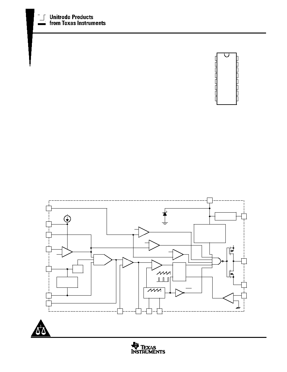
block diagram
UDG-98182
VREF
9
2
16
1
15
10
5
4
DRVOUT
GND
CAI
VCC
OVP/EN
VAOUT
1.9 V
PKLMT
7.5 V
REFERENCE
UVLO
16 V/10 V (UCC2817)
10.5 V/10 V (UCC2818)
VCC
3
OSCILLATOR
12
RT
14
CT
S
Q
R
PWM
LATCH
+
≠
PWM
CAOUT
+
≠
+
≠
+
≠
SS
VOLTAGE
ERROR AMP
8.0 V
13
7
11
VSENSE
VFF
8
IAC
6
MOUT
MIRROR
2:1
X2
+
≠
7.5 V
ENABLE
OVP
˜
X
X
MULT
OSC
CLK
CLK
CURRENT
AMP
16 V (FOR UCC2817 ONLY)
+
≠
0.33 V
ZERO POWER
R
+
≠
Copyright
2001, Texas Instruments Incorporated
PRODUCTION DATA information is current as of publication date.
Products conform to specifications per the terms of Texas Instruments
standard warranty. Production processing does not necessarily include
testing of all parameters.
Please be aware that an important notice concerning availability, standard warranty, and use in critical applications of
Texas Instruments semiconductor products and disclaimers thereto appears at the end of this data sheet.
D, DW, N, and PW PACKAGES
(TOP VIEW)
1
2
3
4
5
6
7
8
16
15
14
13
12
11
10
9
GND
PKLMT
CAOUT
CAI
MOUT
IAC
VAOUT
VFF
DRVOUT
VCC
CT
SS
RT
VSENSE
OVP/EN
VREF

UCC2817, UCC2818, UCC3817, UCC3818
BiCMOS POWER FACTOR PREREGULATOR
SLUS395G - FEBRUARY 2000 - REVISED JUNE 2003
2
www.ti.com
description (continued)
UCC2817 offers an on-chip shunt regulator with low start-up current, suitable for applications utilizing a
bootstrap supply. UCC2818 is intended for applications with a fixed supply (VCC).
Available in the 16-pin D, DW, N and PW packages.
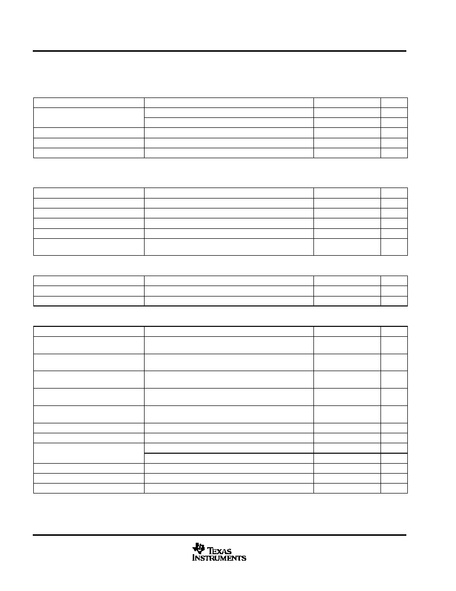
absolute maximum ratings over operating free-air temperature (unless otherwise noted)
Supply voltage VCC
18 V
. . . . . . . . . . . . . . . . . . . . . . . . . . . . . . . . . . . . . . . . . . . . . . . . . . . . . . . . . . . . . . . . . . . . . . . .
Supply current ICC
20 mA
. . . . . . . . . . . . . . . . . . . . . . . . . . . . . . . . . . . . . . . . . . . . . . . . . . . . . . . . . . . . . . . . . . . . . . .
Gate drive current, continuous
0.2 A
. . . . . . . . . . . . . . . . . . . . . . . . . . . . . . . . . . . . . . . . . . . . . . . . . . . . . . . . . . . . . .
Gate drive current
1.2 A
. . . . . . . . . . . . . . . . . . . . . . . . . . . . . . . . . . . . . . . . . . . . . . . . . . . . . . . . . . . . . . . . . . . . . . . . .
Input voltage, CAI, MOUT, SS
8 V
. . . . . . . . . . . . . . . . . . . . . . . . . . . . . . . . . . . . . . . . . . . . . . . . . . . . . . . . . . . . . . . . .
Input voltage, PKLMT
5 V
. . . . . . . . . . . . . . . . . . . . . . . . . . . . . . . . . . . . . . . . . . . . . . . . . . . . . . . . . . . . . . . . . . . . . . . .
Input voltage, VSENSE, OVP/EN
10 V
. . . . . . . . . . . . . . . . . . . . . . . . . . . . . . . . . . . . . . . . . . . . . . . . . . . . . . . . . . . . .
Input current, RT, IAC, PKLMT
10 mA
. . . . . . . . . . . . . . . . . . . . . . . . . . . . . . . . . . . . . . . . . . . . . . . . . . . . . . . . . . . . .
Input current, VCC (no switching)
20 mA
. . . . . . . . . . . . . . . . . . . . . . . . . . . . . . . . . . . . . . . . . . . . . . . . . . . . . . . . . . .
Maximum negative voltage, DRVOUT, PKLMT, MOUT
≠0.5 V
. . . . . . . . . . . . . . . . . . . . . . . . . . . . . . . . . . . . . . . .
Power dissipation
1 W
. . . . . . . . . . . . . . . . . . . . . . . . . . . . . . . . . . . . . . . . . . . . . . . . . . . . . . . . . . . . . . . . . . . . . . . . . . .
Junction temperature, T
J
≠55
∞
C to 150
∞
C
. . . . . . . . . . . . . . . . . . . . . . . . . . . . . . . . . . . . . . . . . . . . . . . . . . . . . . . . . .
Storage temperature, T
stg
≠65
∞
C to 150
∞
C
. . . . . . . . . . . . . . . . . . . . . . . . . . . . . . . . . . . . . . . . . . . . . . . . . . . . . . . . .
Lead temperature, T
sol
(soldering, 10 seconds)
300
∞
C
. . . . . . . . . . . . . . . . . . . . . . . . . . . . . . . . . . . . . . . . . . . . . . .
Power dissipation
1 W
. . . . . . . . . . . . . . . . . . . . . . . . . . . . . . . . . . . . . . . . . . . . . . . . . . . . . . . . . . . . . . . . . . . . . . . . . . .
Stresses beyond those listed under "absolute maximum ratings" may cause permanent damage to the device. These are stress ratings only, and
functional operation of the device at these or any other conditions beyond those indicated under recommended operating conditions is not implied.
Exposure to absolute-maximum-rated conditions for extended periods may affect device reliability.
AVAILABLE OPTIONS
PACKAGE DEVICES
SOIC (D) PACKAGE
SOIC (DW) PACKAGE
PDIP (N) PACKAGE
TSSOP (PW) PACKAGE
TA = TJ
Turn-on
Threshold
16 V
Turn-on
Threshold
10.2 V
Turn-on
Threshold
16 V
Turn-on
Threshold
10.2 V
Turn-on
Threshold
16 V
Turn-on
Threshold
10.2 V
Turn-on
Threshold
16 V
Turn-on
Threshold
10.2 V
≠40
∞
C to 85
∞
C
UCC2817D
UCC2818D
UCC2817DW
UCC2818DW
UCC2817N
UCC2818N
UCC2817PW
UCC2818PW
0
∞
C to 70
∞
C
UCC3817D
UCC3818D
UCC3817DW
UCC3818DW
UCC3817N
UCC3818N
UCC3817PW
UCC3818PW
THERMAL RESISTANCE TABLE
PACKAGE
jc(
∞
C/W)
ja(
∞
C/W)
SOIC≠16 (D)
22
40 to 70
(1)
SOIC≠16 (DW)
26
89 to 102
(1)
PDIP≠16 (N)
12
25 to 50
(1)
TSSOP≠16 (PW)
14
(2)
123 to 147
(2)
NOTES: (1) Specified
ja (junction to ambient) is for devices mounted to 5-inch2 FR4 PC board with one ounce copper
where noted. When resistance range is given, lower values are for 5 inch2 aluminum PC board. Test PWB
was 0.062 inch thick and typically used 0.635-mm trace widths for power packages and 1.3-mm trace
widths for non-power packages with a 100-mil x 100-mil probe land area at the end of each trace.
(2). Modeled data. If value range given for
ja, lower value is for 3x3 inch. 1 oz internal copper ground plane,
higher value is for 1x1-inch. ground plane. All model data assumes only one trace for each non-fused
lead.

UCC2817, UCC2818, UCC3817, UCC3818
BiCMOS POWER FACTOR PREREGULATOR
SLUS395G - FEBRUARY 2000 - REVISED JUNE 2003
3
www.ti.com
electrical characteristics
, T
A
= 0
∞
C to 70
∞
C for the UCC3817 and T
A
= ≠40
∞
C to 85
∞
C for the UCC2817, T
A
= T
J,
VCC = 12 V, R
T
= 22 k
, C
T
= 270 pF, (unless otherwise noted)
supply current section
PARAMETER
TEST CONDITIONS
MIN
TYP
MAX
UNITS
Supply current, off
VCC = (VCC turn-on threshold ≠0.3 V)
150
300
µ
A
Supply current, on
VCC = 12 V, No load on DRVOUT
2
4
6
mA
UVLO section
PARAMETER
TEST CONDITIONS
MIN
TYP
MAX
UNITS
VCC turn-on threshold (UCCx817)
15.4
16
16.6
V
VCC turn-off threshold (UCCx817)
9.4
9.7
V
UVLO hysteresis (UCCx817)
5.8
6.3
V
Maximum shunt voltage (UCCx817)
IVCC = 10 mA
15.4
17
17.5
V
VCC turn-on threshold (UCCx818)
9.7
10.2
10.8
V
VCC turn-off threshold (UCCx818)
9.4
9.7
V
UVLO hysteresis (UCCx818)
0.3
0.5
V
voltage amplifier section
PARAMETER
TEST CONDITIONS
MIN
TYP
MAX
UNITS
Input voltage
TA = 0
∞
C to 70
∞
C
7.387
7.5
7.613
V
Input voltage
TA = ≠40
∞
C to 85
∞
C
7.369
7.5
7.631
V
VSENSE bias current
VSENSE = VREF,
VAOUT = 2.5 V
50
200
nA
Open loop gain
VAOUT = 2 V to 5 V
50
90
dB
High-level output voltage
IL = ≠150
µ
A
5.3
5.5
5.6
V
Low-level output voltage
IL = 150
µ
A
0
50
150
mV
over voltage protection and enable section
PARAMETER
TEST CONDITIONS
MIN
TYP
MAX
UNITS
Over voltage reference
VREF
+0.48
VREF
+0.50
VREF
+0.52
V
Hysteresis
300
500
600
mV
Enable threshold
1.7
1.9
2.1
V
Enable hysteresis
0.1
0.2
0.3
V
current amplifier section
PARAMETER
TEST CONDITIONS
MIN
TYP
MAX
UNITS
Input offset voltage
VCM = 0 V,
VCAOUT = 3 V
≠2
0
2
mV
Input bias current
VCM = 0 V,
VCAOUT = 3 V
≠50
≠100
nA
Input offset current
VCM = 0 V,
VCAOUT = 3 V
25
100
nA
Open loop gain
VCM = 0 V,
VCAOUT = 2 V to 5 V
90
dB
Common-mode rejection ratio
VCM = 0 V to 1.5 V,
VCAOUT = 3 V
60
80
dB
High-level output voltage
IL = ≠120
µ
A
5.6
6.5
6.8
V
Low-level output voltage
IL = 1 mA
0.1
0.2
0.5
V
Gain bandwidth product
See Note 1
2.5
MHz
NOTES: 1. Ensured by design, not production tested.
UCC2817, UCC2818, UCC3817, UCC3818
BiCMOS POWER FACTOR PREREGULATOR
SLUS395G - FEBRUARY 2000 - REVISED JUNE 2003
4
www.ti.com
electrical characteristics
, T
A
= 0
∞
C to 70
∞
C for the UCC3817 and T
A
= ≠40
∞
C to 85
∞
C for the UCC2817, T
A
= T
J,
VCC = 12 V, R
T
= 22 k
, C
T
= 270 pF, (unless otherwise noted)
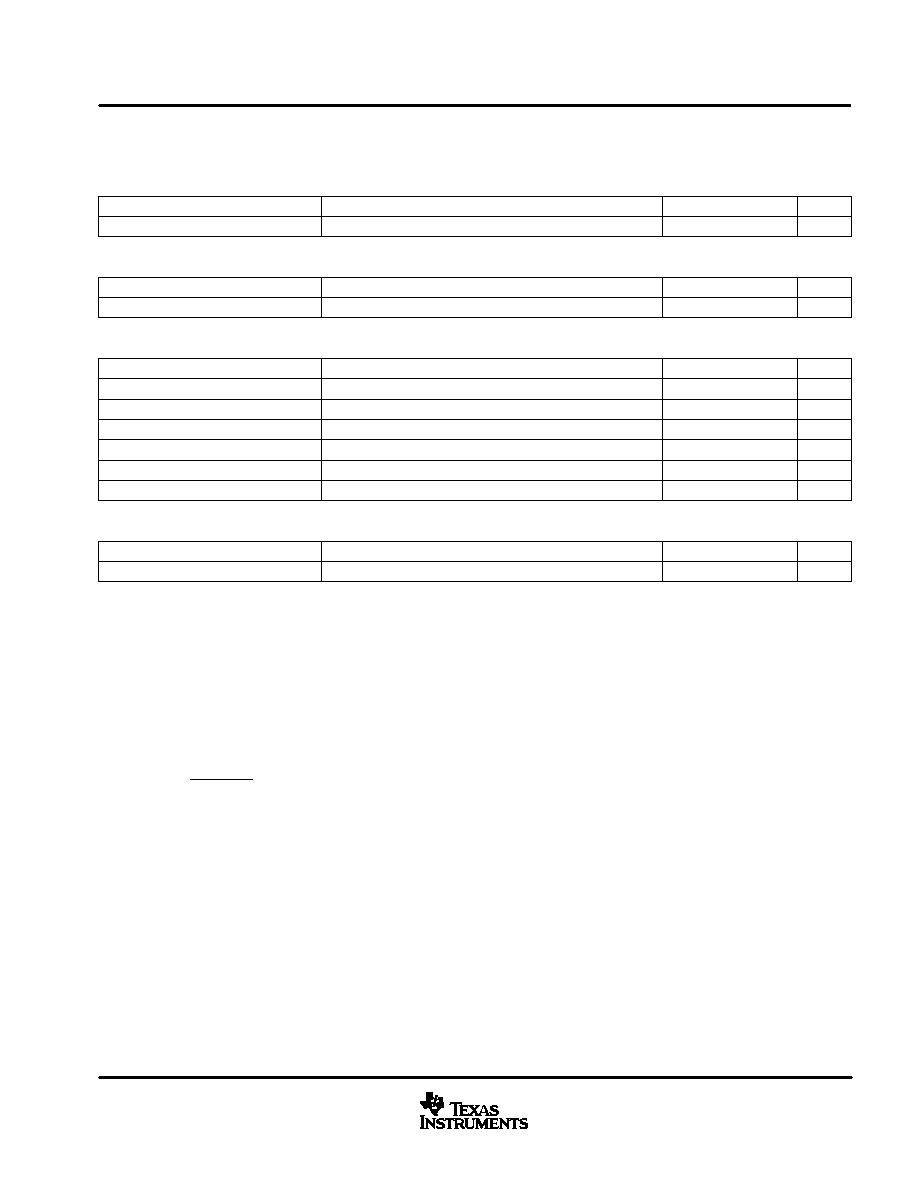
voltage reference section
PARAMETER
TEST CONDITIONS
MIN
TYP
MAX
UNITS
Inp t oltage
TA = 0
∞
C to 70
∞
C
7.387
7.5
7.613
V
Input voltage
TA = ≠40
∞
C to 85
∞
C
7.369
7.5
7.631
V
Load regulation
IREF = 1 mA to 2 mA
0
10
mV
Line regulation
VCC = 10.8 V to 15 V,
See Note 2
0
10
mV
Short-circuit current
VREF = 0 V
≠20
≠25
≠50
mA
NOTES:
2. Reference variation for VCC < 10.8 V is shown in Figure 8.
oscillator section
PARAMETER
TEST CONDITIONS
MIN
TYP
MAX
UNITS
Initial accuracy
TA = 25
∞
C
85
100
115
kHz
Voltage stability
VCC = 10.8 V to 15 V
≠1
1
%
Total variation
Line, temp
80
120
kHz
Ramp peak voltage
4.5
5
5.5
V
Ramp amplitude voltage
(peak to peak)
3.5
4
4.5
V
peak current limit section
PARAMETER
TEST CONDITIONS
MIN
TYP
MAX
UNITS
PKLMT reference voltage
≠15
15
mV
PKLMT propagation delay
150
350
500
ns
multiplier section
PARAMETER
TEST CONDITIONS
MIN
TYP
MAX
UNITS
IMOUT, high line, low power output
current, (0
∞
C to 85
∞
C)
IAC = 500
µ
A, VFF = 4.7 V,
VAOUT = 1.25 V
0
≠6
≠20
µ
A
IMOUT, high line, low power output
current, (≠40
∞
C to 85
∞
C)
IAC = 500
µ
A, VFF = 4.7 V,
VAOUT = 1.25 V
0
≠6
≠23
µ
A
IMOUT, high line, high power output
current
IAC = 500
µ
A, VFF = 4.7 V,
VAOUT = 5 V
≠70
≠90
≠105
µ
A
IMOUT, low line, low power output
current
IAC = 150
µ
A, VFF = 1.4 V,
VAOUT = 1.25 V
≠10
≠19
≠50
µ
A
IMOUT, low line, high power output
current
IAC = 150
µ
A, VFF = 1.4 V,
VAOUT = 5 V
≠268
≠300
≠345
µ
A
IMOUT, IAC limited output current
IAC = 150
µ
A, VFF = 1.3 V,
VAOUT = 5 V
≠250
≠300
≠400
µ
A
Gain constant (K)
IAC = 300
µ
A, VFF = 3 V,
VAOUT = 2.5 V
0.5
1
1.5
1/V
I
zero current
IAC = 150
µ
A, VFF = 1.4 V,
VAOUT = 0.25 V
0
≠2
µ
A
IMOUT, zero current
IAC = 500
µ
A, VFF = 4.7 V,
VAOUT = 0.25 V
0
≠2
µ
A
IMOUT, zero current, (0
∞
C to 85
∞
C)
IAC = 500
µ
A, VFF = 4.7 V,
VAOUT = 0.5 V
0
≠3
µ
A
IMOUT, zero current, (≠40
∞
C to 85
∞
C)
IAC = 500
µ
A, VFF = 4.7 V,
VAOUT = 0.5 V
0
≠3.5
µ
A
Power limit (IMOUT x VFF)
IAC = 150
µ
A, VFF = 1.4 V,
VAOUT = 5 V
≠375
≠420
≠485
µ
W
UCC2817, UCC2818, UCC3817, UCC3818
BiCMOS POWER FACTOR PREREGULATOR
SLUS395G - FEBRUARY 2000 - REVISED JUNE 2003
5
www.ti.com
electrical characteristics
, T
A
= 0
∞
C to 70
∞
C for the UCC3817 and T
A
= ≠40
∞
C to 85
∞
C for the UCC2817, T
A
= T
J,
VCC = 12 V, R
T
= 22 k
, C
T
= 270 pF, (unless otherwise noted)
feed-forward section
PARAMETER
TEST CONDITIONS
MIN
TYP
MAX
UNITS
VFF output current
IAC = 300
µ
A
≠140
≠150
≠160
µ
A
soft start section
PARAMETER
TEST CONDITIONS
MIN
TYP
MAX
UNITS
SS charge current
≠6
≠10
≠16
µ
A
gate driver section
PARAMETER
TEST CONDITIONS
MIN
TYP
MAX
UNITS
Pullup resistance
IO = ≠100 mA to ≠200 mA
5
12
Pulldown resistance
IO = 100 mA
2
10
Output rise time
CL = 1 nF,
RL = 10
,
VDRVOUT = 0.7 V to 9.0 V
25
50
ns
Output fall time
CL = 1 nF,
RL = 10
,
VDRVOUT = 9.0 V to 0.7 V
10
50
ns
Maximum duty cycle
93
95
99
%
Minimum controlled duty cycle
At 100 kHz
2
%
zero power section
PARAMETER
TEST CONDITIONS
MIN
TYP
MAX
UNITS
Zero power comparator threshold
Measured on VAOUT
0.20
0.33
0.50
V
pin descriptions
CAI: (current amplifier noninverting input) Place a resistor between this pin and the GND side of current sense
resistor. This input and the inverting input (MOUT) remain functional down to and below GND.
CAOUT: (current amplifier output) This is the output of a wide bandwidth operational amplifier that senses line
current and commands the PFC pulse-width modulator (PWM) to force the correct duty cycle. Compensation
components are placed between CAOUT and MOUT.
CT: (oscillator timing capacitor) A capacitor from CT to GND sets the PWM oscillator frequency according to:
f
[
0.6
RT
CT
The lead from the oscillator timing capacitor to GND should be as short and direct as possible.
DRVOUT: (gate drive) The output drive for the boost switch is a totem-pole MOSFET gate driver on DRVOUT.
Use a series gate resistor to prevent interaction between the gate impedance and the output driver that might
cause the DRVOUT to overshoot excessively. See characteristic curve (Figure 13) to determine minimum
required gate resister value. Some overshoot of the DRVOUT output is always expected when driving a
capacitive load.
GND: (ground) All voltages measured with respect to ground. VCC and REF should be bypassed directly to
GND with a 0.1-
µ
F or larger ceramic capacitor.