Document Outline
- FEATURES
- DESCRIPTION
- SIMPLIFIED APPLICATION DIAGRAM
- ABSOLUTE MAXIMUM RATINGS
- ELECTROSTATIC DISCHARGE (ESD) PROTECTION
- AVAILABLE OPTIONS
- ELECTRICAL CHARACTERISTICS
- supply current
- undervoltage lockout (UVLO)
- voltage amplifier
- PFC stage overvoltage protection and enable
- current amplifier
- oscillator
- voltage reference
- peak current limit
- multiplier
- zero power
- PFC gate driver
- PWM stage undervoltage lockout (UVLO2)
- PWM stage soft-start
- PWM stage duty cycle clamp
- PWM stage pulse-by-pulse current sense
- PWM stage overcurrent limit
- PWM stage gate driver
- TERMINAL FUNCTIONS
- BLOCK DIAGRAM
- DETAILED PIN DESCRIPTIONS
- CAOUT (Pin 15):
- CT_BUFF (Pin 5):
- D_MAX (Pin 4):
- GND (Pin 6):
- GT1 (Pin 12):
- GT2 (Pin 10):
- IAC (Pin 18):
- ISENSE1 (Pin 16):
- ISENSE2 (Pin 8):
- MOUT (Pin 17):
- PKLMT (Pin 14):
- PWRGND ( Pin 11):
- RT (Pin 2):
- SS2 (pin 13):
- VAOUT (Pin 1):
- VCC (Pin 9):
- VERR (Pin 7):
- VFF (Pin 19):
- VREF (Pin 20):
- VSENSE (Pin 3):
- APPLICATION INFORMATION
- selection of controller options
- design procedure
- developing the internal parameters
- power stage elements
- PFC stage control
- multiplier
- PFC current loop control
- PFC voltage loop
- PWM stage control
- Soft-start
- REFERENCE DESIGN
- TYPICAL CHARACTERISTICS
- REFERENCES
- RELATED PRODUCTS
- MECHANICAL DATA
- DW (R-PDSO-G**) PLASTIC SMALL-OUTLINE PACKAGE
- N (R-PDIP-T**) PLASTIC DUAL-IN-LINE PACKAGE
UCC28510, UCC28511, UCC28512, UCC28513,
UCC28514, UCC28515, UCC28516, UCC28517
SLUS517B - DECEMBER 2002 - REVISED AUGUST 2004
ADVANCED PFC/PWM
COMBINATION CONTROLLERS
1
www.ti.com
FEATURES
D
Provides Control of PFC and PWM Power
Stages In One Device
D
Leading-Edge PFC, Trailing-Edge PWM
Modulation for Reduced Ripple
D
Built-In Sequencing of PFC and PWM
Turn-On
D
2-A Source and 3-A Sink Gate Drive for Both
PFC and PWM Stages
D
Typical 16-ns Rise Time and 7-ns Fall Time
into 1-nF Loads
PFC Features
- Average-Current-Mode Control for
Continuous Conduction Mode Operation
- Highly-Linear Multiplier for Near-Unity
Power Factor
- Input Voltage Feedforward Implementation
- Improved Load Transient Response
- Accurate Power Limiting
- Zero Power Detect
PWM Features
- Peak-Current-Mode Control Operation
- 1:1 or 1:2 PFC:PWM Frequency Options
- Programmable maximum duty cycle
- Programmable Soft-Start
- Two Hysteresis Options for Differing
Hold-Up Time Requirements
DESCRIPTION
The UCC28510 series of combination PFC/PWM
controllers provide complete control functionality
for any off-line power system requiring
compliance with the IEC1000-3-2 harmonic
reduction requirements. By combining the control
and drive signals for the PFC and the PWM stages
into a single device, significant performance and
cost benefits are gained. By managing the
modulation mechanisms of the two stages
(leading-edge modulation for PFC and
trailing-edge modulation for PWM), the ripple
current in the boost capacitor is minimized.
Based on the average current mode control
architecture with input voltage feedforward of prior
PFC/PWM combination controllers, these devices
offer performance advantages. Two new key
PWM features are programmable maximum duty
cycle and the 2x PWM frequency options to the
base PFC frequency. For the PFC stage, the
devices feature an improved multiplier and the
use of a transconductance amplifier for enhanced
transient response.
The core of the PFC section is in a three-input
multiplier that generates the reference signal for
the line current. The UCC28510 series features a
highly linearized multiplier circuit capable of
producing a low distortion reference for the line
current over the full range of line and load
conditions. A low-offset, high-bandwidth current
error amplifier ensures that the actual inductor
current (sensed through a resistor in the return
path) follows the multiplier output command
signal. The output voltage error is processed
through a transconductance voltage amplifier.
PRODUCTION DATA information is current as of publication date.
Products conform to specifications per the terms of Texas Instruments
standard warranty. Production processing does not necessarily include
testing of all parameters.
Copyright
2004, Texas Instruments Incorporated

UCC28510, UCC28511, UCC28512, UCC28513,
UCC28514, UCC28515, UCC28516, UCC28517
SLUS517B - DECEMBER 2002 - REVISED AUGUST 2004
2
www.ti.com
DESCRIPTION (CONTINUED)
The transient response of the circuit is enhanced by allowing a much faster charge/discharge of the voltage
amplifier output capacitance when the output voltage falls outside a certain regulation window. A number of
additional features such as UVLO circuit with selectable hysteresis levels, an accurate reference voltage for the
voltage amplifier, zero power detect, OVP/enable, peak current limit, power limiting, high-current output gate
driver characterize the PFC section.
The PWM section features peak current mode control (with a ramp signal available to add slope compensation),
programmable soft-start, accurate maximum duty cycle clamp, peak current limit and high-current output gate
driver. The oscillator for the combination controller is available in two versions. In UCC28510, UCC28511,
UCC28512, and UCC28513, the PWM and the PFC circuits are switched at the same frequency. In the
UCC28514, UCC28515, UCC28516, and UCC28517, the PWM stage frequency is twice that of the PFC
frequency. The PWM stage is suppressed until the PFC output has reached 90% of its programmed value during
startup. During line dropout and turn off, the device allows the PWM stage to operate until the PFC output has
dropped to 47% (UCC28512, UCC28513, UCC28516, and UCC28517) or 71% (UCC28510, UCC28511,
UCC28514, and UCC28515) of its nominal value. See available options table on page 1 for a summary of
options.
The UCC28510 family also features leading-edge modulation for the PFC stage and trailing-edge modulation
for the PWM stage in order to reduce the ripple current in the boost output capacitor. The current amplifier
implementation associated with this scheme also results in better noise immunity.
Available in 20-pin N and DW packages.
SIMPLIFIED APPLICATION DIAGRAM
12
3
16
18
10
5
7
2
UCC2851X
GT1
VSENSE
ISENSE1
IAC
GT2
VREF
VERR
RT
+
-
D1
VAC
15
14
13
11
17
19
20
PWRGND
VAOUT
1
6
VFF
MOUT
CAOUT
PKLMT
SS2
8
9
D_MAX
CT_BUFF
GND
ISENSE2
VCC
REF
PRIMARY
SECONDARY
+
-
VOUT
+
4
REF
BIAS
RECT
+
-
PWM
V-LOOP
Z
Z
Z

UCC28510, UCC28511, UCC28512, UCC28513,
UCC28514, UCC28515, UCC28516, UCC28517
SLUS517B - DECEMBER 2002 - REVISED AUGUST 2004
3
www.ti.com
ABSOLUTE MAXIMUM RATINGS
over operating free-air temperature (unless otherwise noted)
}
Supply voltage VCC
Idle
20 V
. . . . . . . . . . . . . . . . . . . . . . . . . . . . . . . . . . . . . . . . . . . . . . . . . . . . . . . . . . . . . . . . . . . . . . . . . . . . . . . . . .
Operating
18 V
. . . . . . . . . . . . . . . . . . . . . . . . . . . . . . . . . . . . . . . . . . . . . . . . . . . . . . . . . . . . . . . . . . . . . . . . . . . . .
Gate drive current (GT1, GT2)
Continuous
0.4 A
. . . . . . . . . . . . . . . . . . . . . . . . . . . . . . . . . . . . . . . . . . . . . . . . . . . . . . . . . . . . . . . . . . . . . . . . . .
Pulsed
Sourcing
-2.5 A
. . . . . . . . . . . . . . . . . . . . . . . . . . . . . . . . . . . . . . . . . . . . . . . . . . . . . . . . . . . . . . . . . . . .
Sinking
3.5 A
. . . . . . . . . . . . . . . . . . . . . . . . . . . . . . . . . . . . . . . . . . . . . . . . . . . . . . . . . . . . . . . . . . . . . . .
Maximum GT1, GT2 voltage
-0.5 V to VCC+0.3 V
. . . . . . . . . . . . . . . . . . . . . . . . . . . . . . . . . . . . . . . . . . . . . . . . . .
Input voltage
VSENSE
0 V to 11 V
. . . . . . . . . . . . . . . . . . . . . . . . . . . . . . . . . . . . . . . . . . . . . . . . . . . . . . . . . . . . . . . . . . . . . . .
D_MAX, SS2, CAOUT, ISENSE1, MOUT, VFF
-0.5 V to VREF+0.3 V
. . . . . . . . . . . . . . . . . . . . . . . . . . . . .
VAOUT, CT_BUFF, ISENSE2, PKLMT
-0.5 V to 6 V
. . . . . . . . . . . . . . . . . . . . . . . . . . . . . . . . . . . . . . . . . . . .
Pin Current
RT
-0.5 mA
. . . . . . . . . . . . . . . . . . . . . . . . . . . . . . . . . . . . . . . . . . . . . . . . . . . . . . . . . . . . . . . . . . . . . . . . . . . . . . . .
VFF
-5 mA
. . . . . . . . . . . . . . . . . . . . . . . . . . . . . . . . . . . . . . . . . . . . . . . . . . . . . . . . . . . . . . . . . . . . . . . . . . . . . . . .
CT_BUFF
1 mA
. . . . . . . . . . . . . . . . . . . . . . . . . . . . . . . . . . . . . . . . . . . . . . . . . . . . . . . . . . . . . . . . . . . . . . . . . . .
VAOUT, VERR, ISENSE2, SS2, CAOUT, IAC
10 mA
. . . . . . . . . . . . . . . . . . . . . . . . . . . . . . . . . . . . . . . . . . .
Maximum pin capacitance
ISENSE2
220 pF
. . . . . . . . . . . . . . . . . . . . . . . . . . . . . . . . . . . . . . . . . . . . . . . . . . . . . . . . . . . . . . . . . . . . . . . . . . .
Operating junction temperature range, T
J
-55
0
C to 150
0
C
. . . . . . . . . . . . . . . . . . . . . . . . . . . . . . . . . . . . . . . . . .
Storage Temperature range, T
stg
-65
0
C to 150
0
C
. . . . . . . . . . . . . . . . . . . . . . . . . . . . . . . . . . . . . . . . . . . . . . . . .
Lead temperature 1.6mm (1/16 inch from case for 10 seconds)
300
0
C
. . . . . . . . . . . . . . . . . . . . . . . . . . . . . . . . .
Power dissipation
PDIP (N) package
1 W
. . . . . . . . . . . . . . . . . . . . . . . . . . . . . . . . . . . . . . . . . . . . . . . . . . . . . . . . . . . . . . . . . . . . .
SOIC (DW) package
0.7 W
. . . . . . . . . . . . . . . . . . . . . . . . . . . . . . . . . . . . . . . . . . . . . . . . . . . . . . . . . . . . . . . . . .
Stresses beyond those listed under "absolute maximum ratings" may cause permanent damage to the device. These are stress ratings only, and
functional operation of the device at these or any other conditions beyond those indicated under recommended operating conditions is not implied.
Exposure to absolute-maximum-rated conditions for extended periods may affect reliability.
Currents are positive into, negative out of the specified terminal. All voltages are referenced to GND.
ELECTROSTATIC DISCHARGE (ESD) PROTECTION
PARAMETER
MAX
UNITS
Human body model
2.5
kV
CDM
0.5
kV
AVAILABLE OPTIONS
{}
OPTIONS
PACKAGED DEVICES
PFC:PWM
FREQUENCY
RATIO
UVLO
TURN-ON (V)
UVLO
HYSTERESIS (V)
PWM UVLO2
TURN-OFF (V)
PWM UVLO2
HYSTERESIS (V)
PDIP-20
(N)
SOIC W-20
(DW)
1:1
16
6.3
5.30
1.45
UCC28510N
UCC28510DW
1:1
10.2
0.5
5.30
1.45
UCC28511N
UCC28511DW
1:1
16
6.3
3.55
3.2
UCC28512N
UCC28512DW
1:1
10.2
0.5
3.55
3.2
UCC28513N
UCC28513DW
1:2
16
6.3
5.30
1.45
UCC28514N
UCC28514DW
1:2
10.2
0.5
5.30
1.45
UCC28515N
UCC28515DW
1:2
16
6.3
3.55
3.2
UCC28516N
UCC28516DW
1:2
10.2
0.5
3.55
3.2
UCC28517N
UCC28517DW
The DW package is available taped and reeled. Add R suffix to device type (e.g. UCC28510DWR) to order quantities of 2000 devices per reel.
All devices are rated from -40
∞
C to +105
∞
C.

UCC28510, UCC28511, UCC28512, UCC28513,
UCC28514, UCC28515, UCC28516, UCC28517
SLUS517B - DECEMBER 2002 - REVISED AUGUST 2004
4
www.ti.com
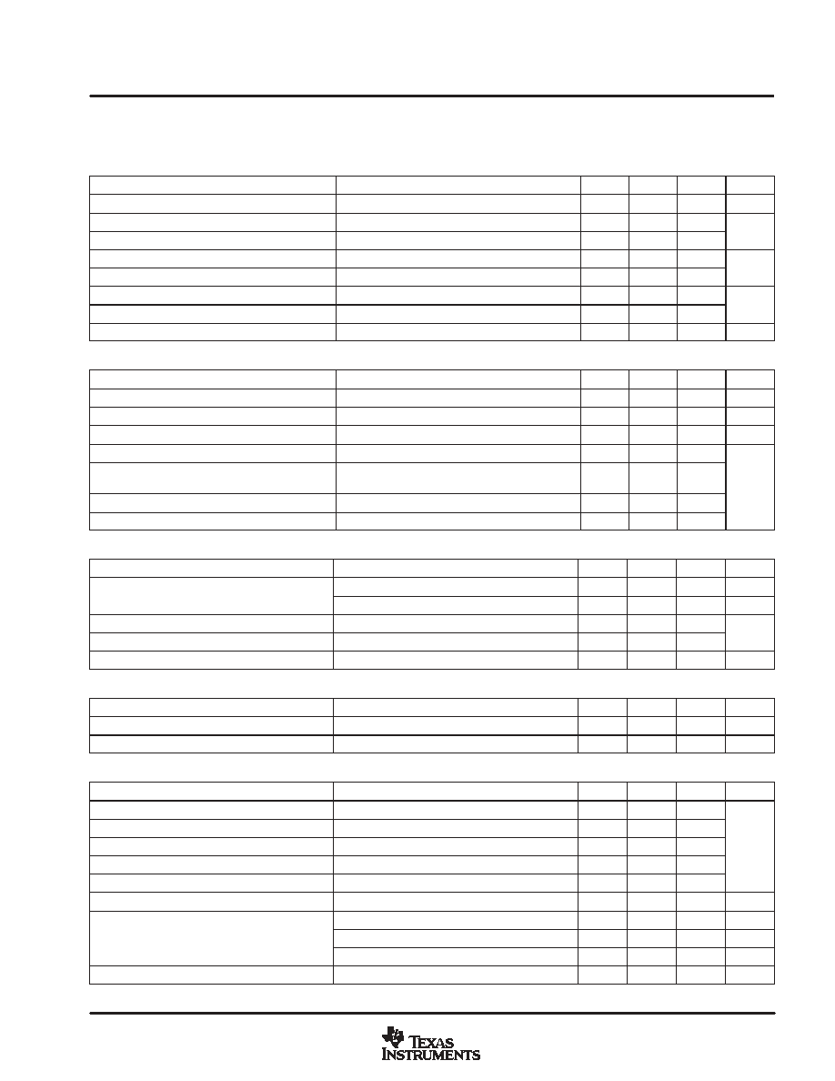
ELECTRICAL CHARACTERISTICS
T
A
= ≠40
∞
C to 105
∞
C for the UCC2851x, T
A
= T
J
, VCC = 12 V, R
T
= 156 k
,
R
CT_BUFF
= 10 k
(unless otherwise noted)
supply current
PARAMETER
TEST CONDITIONS
MIN
TYP
MAX
UNITS
Supply current, off
VCC turn-on threshold -300 mV
100
150
µ
A
Supply current, on
no load on GT1 or GT2
4
6
mA
undervoltage lockout (UVLO)
PARAMETER
TEST CONDITIONS
MIN
TYP
MAX
UNITS
VCC turn-on threshold
UCC28510
UCC28512
UCC28514
UCC28516
15.4
16
16.6
VCC turn-on threshold
UCC28511
UCC28513
UCC28515
UCC28517
9.7
10.2
10.8
VCC turn-off threshold
UCC2851X
9.1
9.7
10.6
V
UVLO hysteresis
UCC28510
UCC28512
UCC28514
UCC28516
5.8
6.3
6.8
V
UVLO hysteresis
UCC28511
UCC28513
UCC28515
UCC28517
0.3
0.5
0.8
voltage amplifier
PARAMETER
TEST CONDITIONS
MIN
TYP
MAX
UNITS
Input voltage
25
∞
C
7.39
7.50
7.61
V
Input voltage
Over temperature
7.35
7.50
7.65
V
VSENSE bias current
VSENSE = VREF
100
300
nA
Open loop gain
2 V
VAOUT
4 V
50
60
dB
High-level output voltage
ILOAD = ≠150
µ
A
5.3
5.5
5.6
V
Low-level output voltage
ILOAD = 150
µ
A
0.00
0.05
0.15
V
gM conductance
IVAOUT = -20
µ
A to 20
µ
A
70
100
130
µ
S
Maximum source current
-1
-3.5
mA
Maximum sink current
1
3.5
mA
PFC stage overvoltage protection and enable
PARAMETER
TEST CONDITIONS
MIN
TYP
MAX
UNITS
Overvoltage reference window
VREF
+ 0.440
VREF
+ 0.490
VREF
+ 0.540
V
Hysteresis
300
500
600
mV
Enable threshold
1.7
1.9
2.1
V
Enable hysteresis
0.08
0.2
0.3
V
UCC28510, UCC28511, UCC28512, UCC28513,
UCC28514, UCC28515, UCC28516, UCC28517
SLUS517B - DECEMBER 2002 - REVISED AUGUST 2004
5
www.ti.com
ELECTRICAL CHARACTERISTICS
T
A
= ≠40
∞
C to 105
∞
C for the UCC2851x, T
A
= T
J
, VCC = 12 V, R
T
= 156 k
,
R
CT_BUFF
= 10 k
(unless otherwise noted)
current amplifier
PARAMETER
TEST CONDITIONS
MIN
TYP
MAX
UNITS
Input offset voltage
VCM = 0 V,
VCAOUT = 3 V
≠5
0
5
mV
Input bias current
VCM = 0 V,
VCAOUT = 3 V
-50
-100
nA
Input offset current
VCM = 0 V,
VCAOUT = 3 V
25
100
nA
Open loop gain
VCM = 0 V,
2 V
VCAOUT
5 V
90
dB
Common-mode rejection ratio
0 V
VCM
1.5 V, VCAOUT = 3 V
80
dB
High-level output voltage
ILOAD = ≠500
µ
A
5.6
6.3
7.0
V
Low-level output voltage
ILOAD = 500
µ
A
0
0.2
0.5
V
Gain bandwidth product(1)
See Note 1
2.0
MHz
oscillator
PARAMETER
TEST CONDITIONS
MIN
TYP
MAX
UNITS
fPWM, PWM frequency, initial accuracy
TA = 25
∞
C
170
200
230
kHz
Frequency, voltage stability
10.8 V
VCC
15 V
-1%
1%
Frequency, total variation
Line, Temp
160
240
kHz
dc-to-dc ramp peak voltage
4.5
5.0
5.5
dc-to-dc ramp amplitude voltage(1)
(peak-to-peak)
4.0
V
PFC ramp peak voltage
4.5
5.0
5.5
V
PFC ramp amplitude voltage (peak-to-peak)
3.5
4.0
4.5
voltage reference
PARAMETER
TEST CONDITIONS
MIN
TYP
MAX
UNITS
Input voltage
25
∞
C
7.39
7.50
7.61
V
Input voltage
Over temperature
7.35
7.50
7.65
V
Load regulation
IREF = -1 mA to -6 mA
5
15
mV
Line regulation
10.8 V
VCC
15 V
1
10
mV
Short circuit current
VREF = 0V
-20
≠25
-50
mA
peak current limit
PARAMETER
TEST CONDITIONS
MIN
TYP
MAX
UNITS
PKLMT reference voltage
≠20
0
20
mV
PKLMT propagation delay
PKLMT to GT1
150
300
500
ns
multiplier
PARAMETER
TEST CONDITIONS
MIN
TYP
MAX
UNITS
IMOUT, high-line low-power output current
IAC = 500
µ
A, VFF = 4.7 V,
VAOUT = 1.25 V
-3
≠6
-9
IMOUT, high-line high-power output current
IAC = 500
µ
A, VFF = 4.7 V,
VAOUT = 5 V
-75
≠90
-110
IMOUT, low-line low-power output current
IAC = 150
µ
A, VFF = 1.4 V,
VAOUT = 1.25 V
-10
≠15
-50
µ
A
IMOUT, low-line high-power output current
IAC = 150
µ
A, VFF = 1.4 V,
VAOUT = 5 V
-245
≠290
-330
µ
A
IMOUT, IAC-limited output current
IAC = 150
µ
A, VFF = 1.3 V,
VAOUT = 5 V
-245
≠290
-330
Gain constant (k)
IAC = 300
µ
A, VFF = 2.8 V,
VAOUT = 2.5 V
0.8
1
1.2
1/V
IAC = 150
µ
A, VFF = 1.4 V,
VAOUT = 0.25 V
0
≠0.2
µ
A
IMOUT, zero current
IAC = 500
µ
A, VFF = 4.7 V,
VAOUT = 0.25 V
0
≠0.2
µ
A
IMOUT, zero current
IAC = 500
µ
A, VFF = 4.7 V,
VAOUT = 0.5 V
0
≠0.2
µ
A
Power limit (IMOUT
◊
VFF)
IAC = 150
µ
A, VFF = 1.4 V,
VAOUT = 5 V
-343
≠406
-462
µ
W
1. Ensured by design. Not 100% tested in production.