 | –≠–ª–µ–∫—Ç—Ä–æ–Ω–Ω—ã–π –∫–æ–º–ø–æ–Ω–µ–Ω—Ç: UCC3882PW | –°–∫–∞—á–∞—Ç—å:  PDF PDF  ZIP ZIP |

www.ti.com
FEATURES
DESCRIPTION
UDG-97047-1
CAM
CAO
OVP
OVP (+ 17.5%)
OV
OV (+ 9%)
VSNS
VFB
Voltage
Amplifier
Current
Amplifier
3 V
UV
UV (-9%)
S
R
Q
Turn
On
Delay
Current Sense
Amplifier
RT
PWRGD
VDRVHI
GATEHI
PGND
Anti Cross
Condition
Turn
On
Delay
RT
VDRVLO
GATELO
Foldback
Current
Limit
1.37 V
VSNS
X16
COMP
ISOUT
IS-
IS+
Output Offset
5 V REF
D0
D1
D2
D3
D4
D/C Converter
2 V - 3.5 V, 100 mV
or
1.3 V - 2.05 V, 50 mV
COMMAND
CT
RT
OSC
VIN
10.5 V/10 V
UVLO
4.3 V/4.2 V
5 V
REF
GND
VREF
VIN
EN
4
6
15
16
8
7
27
26
24
23
22
6
1
20
14
13
2
19
18
12
10
11
28
21
9
17
UCC3882/-1
SLUS294A ≠ MARCH 1999 ≠ REVISED OCTOBER 2005
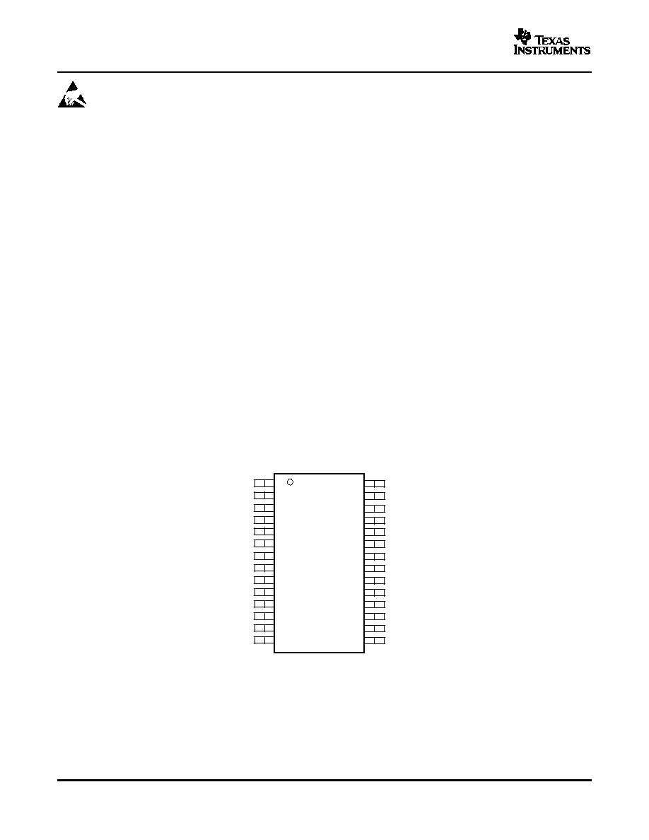
AVERAGE CURRENT MODE SYNCHRONOUS
CONTROLLER WITH 5-BIT DAC
∑
Combined DAC/Voltage Monitor and PWM
The UCC3882 combines high precision reference and
With Synchronous Rectification Functions
voltage monitoring circuitry with average current
mode
PWM
synchronous
rectification
controller
∑
5-Bit Digital-to-Analog (DAC) Converter
circuitry to power high-end microprocessors with a
∑
1% DAC/Reference Combined Accuracy
minimum of external components. The UCC3882
∑
Compatible with 5 V and 12 V Systems and 12
converts 5 V or 12 V to an adjustable output ranging
V-Only Systems
from 1.8VDC to 2.05VDC in 50 mV steps and
2.1VDC to 3.5VDC in 100 mV steps with 1% DC
∑
Low Offset Current Sense Amplifier
system accuracy.
∑
Programmable Oscillator Frequency Practical
to 700 kHz
∑
Foldback Current Limiting
∑
Overvoltage and Undervoltage Fault Windows
∑
2-
Totem Pole Outputs with Programmable
Dead Times to Eliminate Cross-Conduction
∑
Chip Disable Function
BLOCK DIAGRAM
Please be aware that an important notice concerning availability, standard warranty, and use in critical applications of Texas
Instruments semiconductor products and disclaimers thereto appears at the end of this data sheet.
PRODUCTION DATA information is current as of publication date.
Copyright © 1999≠2005, Texas Instruments Incorporated
Products conform to specifications per the terms of the Texas
Instruments standard warranty. Production processing does not
necessarily include testing of all parameters.
www.ti.com
DESCRIPTION (CONTINUED)
CONNECTION DIAGRAM
1
2
3
4
5
6
7
8
9
10
11
12
13
14
28
27
26
25
24
23
22
21
20
19
18
17
16
15
VSNS
PWRGD
NC
CAM
CAO
OSOUT
IS+
IS-
VIN
VDRVLO
GATELO
PGND
RT
CT
GND
D0
D1
NC
D2
D3
D4
VREF
COMMAND
VDRVHI
GATEHI
EN
COMP
VFB
N, DW or PW PACKAGES
(TOP VIEW)
NC - No internal connection
UCC3882/-1
SLUS294A ≠ MARCH 1999 ≠ REVISED OCTOBER 2005
These devices have limited built-in ESD protection. The leads should be shorted together or the device
placed in conductive foam during storage or handling to prevent electrostatic damage to the MOS gates.
The DAC output voltage is directly compatible with
The voltage and current amplifiers have 2.5 MHz
Intel's 5-bit VID code (
Table 1
) which covers 1.3 V to
gain-bandwidth product to satisfy high performance
2.05 V in 50 mV steps and 2.1 V to 3.5 V in 100 mV
system requirements. The internal current sense
steps.
The
accuracy
of
the
DAC/reference
amplifier permits the use of a low value current sense
combination is better than 1%. Undervoltage lockout
resistor,
minimizing
power
loss.
The
oscillator
circuitry assures the correct logic states at the
frequency is externally programmed with RT and CT.
outputs during power up and power down. The
The foldback circuit reduces the converter short
overvoltage and undervoltage comparators monitor
circuit current limit to 50% of its nominal value when
the system output voltage and indicate when it rises
the
converter
is
short-circuited,
minimizing
above or falls below its designed value by more than
component stress and dissipation during abnormal
9%. A second overvoltage comparator digitally forces
conditions. The gate drivers are low impedance totem
GATEHI off and GATELO on when the system output
pole output stages capable of driving large external
voltage exceeds its designed value by more than
MOSFETs. Cross conduction is eliminated internally
17.5%.
by programming the dead time between turn-off and
turn on of the external high side and synchronous
For all of the parts, grounding the EN pin disables the
MOSFETs.
GATEHI and GATELO outputs, shutting down the
power supply. For the 3882, programming a DAC
This device is available in a 28-pin wide body surface
output voltage below 1.8 V, or programming all of the
mount package. The UCC3882 is specified for
VID pins high also disables the GATEHI and
operation from 0
∞
C to 70
∞
C.
GATELO outputs. For the ≠1 option parts, the
GATEHI and GATELO outputs are switching, and the
power
supply
output
voltage
regulates
at
the
programmed DAC output voltage for all VID codes.
2
www.ti.com
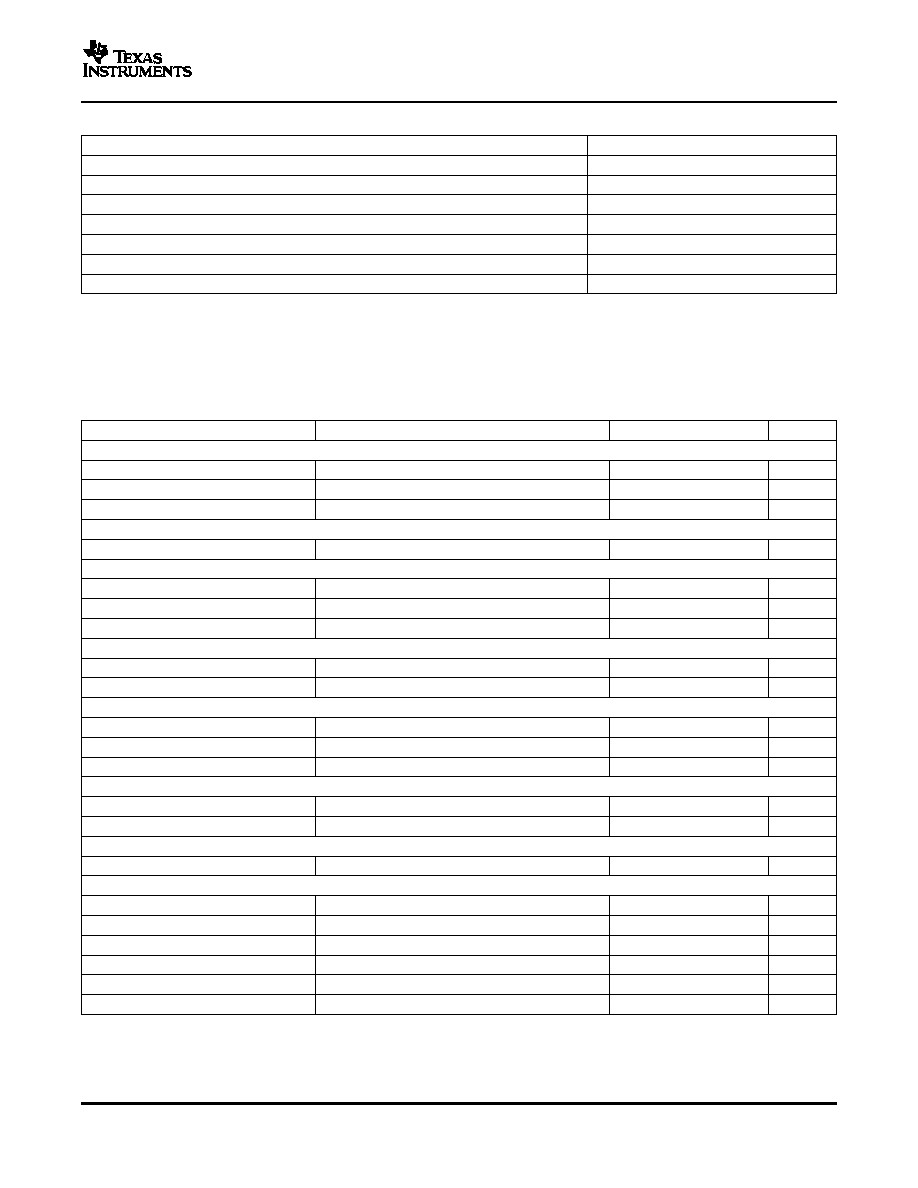
ABSOLUTE MAXIMUM RATINGS
(1)
ELECTRICAL CHARACTERISTICS
UCC3882/-1
SLUS294A ≠ MARCH 1999 ≠ REVISED OCTOBER 2005
UNIT
VDRVHI, GATEHI
(2)
≠0.3 V to 20 V
VDRVLO, GATELO
≠0.3 V to 15 V
All other pins referenced to GND
≠0.3 V to 5.3 V
VIN
15 V
Storage Temperature
≠65
∞
C to 150
∞
C
Junction Temperatur
≠55
∞
C to 150
∞
C.
Lead Temperature (Soldering, 10 sec.)
300
∞
C
(1)
Currents are positive into, negative out of the specified terminal. Consult Packaging Section of Databook for thermal limitations and
considerations of packages.
(2)
20 V at no load. Derate to 18.5 V when used with capacitive loads of greater than 1000 pF in series with less than 20
.
Unless otherwise specified, VIN = VDRVHI = VDRVLO = 12 V, VSNS = 3.5 V, V
D0
= V
D1
= V
D2
= V
D3
= V
D4
= 0 V, R
T
= 13 k,
C
T
= 1.8 nF, EN = Open, 0
∞
C < T
A
< 70
∞
C, T
A
= T
J
.
PARAMETER
TEST CONDITIONS
MIN
TYP
MAX
UNIT
UNDERVOLTAGE LOCKOUT
VIN UVLO Turn-on Threshold
10.5
10.8
V
VIN UVLO Turn-off Threshold
9.5
10
V
UVLO Threshold Hysteresis
300
500
700
mV
SUPPLY CURRENT
l
IN
EN = 0 V
7
12
mA
DAC/REFERENCE
COMMAND Voltage Accuracy
10.8 V < VIN < 13.2 V, I
RE
F = 0 mA
(1)
≠1%
1%
D0-D4 Voltage High
DX Pin Floating
5
5.2
V
D0-D4 Input Bias Current
DX Pin Tied to GND
≠120
≠70
≠20
mA
OVP COMPARATOR
Trip Point
% Over COMMAND Voltage
(2)
10
17
25
µ
V
Hysteresis
20
mV
OV COMPARATOR
Trip Point
% Over COMMAND Voltage
(2)
5%
9%
12%
Hysteresis
20
mV
PWRGD On Resistance
470
UV COMPARATOR
Trip Point
% Over COMMAND Voltage
(2)
≠12%
≠9%
≠5%
Hysteresis
20
mV
ENABLE PIN
Pull Up Current
V
EN
= 2.5 V
≠80
≠50
≠20
µ
A
VOLTAGE ERROR AMPLIFIER
Input Offset Voltage
V
CM
= 3 V
≠10
0
10
mV
Input Bias Current
V
CM
= 3 V
≠0.5
0.5
µ
A
Open Loop Gain
2.05 V < V
COMP
< 3.05 V
90
dB
Power Supply Rejection Ratio
10.8 V < VIN < 15 V
85
dB
Output Sourcing Current
V
VFB
= 2 V, V
COMMAND
= V
COMP
= 2.5 V
≠1.6
≠0.8
mA
Output Sinking Current
V
VFB
= 3 V, V
COMMAND
= V
COMP
= 2.5 V
1
mA
(1)
This test measures the combined errors of the COMMAND voltage and the voltage amplifier offset voltage. Applies to all DAC codes
from 1.8 V to 3.5 V.
(2)
This percentage is measured with respect to the ideal COMMAND voltage programmed by the D0≠D4 pins.
3

www.ti.com
PIN DESCRIPTIONS
UCC3882/-1
SLUS294A ≠ MARCH 1999 ≠ REVISED OCTOBER 2005
ELECTRICAL CHARACTERISTICS (continued)
Unless otherwise specified, VIN = VDRVHI = VDRVLO = 12 V, VSNS = 3.5 V, V
D0
= V
D1
= V
D2
= V
D3
= V
D4
= 0 V, R
T
= 13 k,
C
T
= 1.8 nF, EN = Open, 0
∞
C < T
A
< 70
∞
C, T
A
= T
J
.
PARAMETER
TEST CONDITIONS
MIN
TYP
MAX
UNIT
CURRENT SENSE AMPLIFIER
Gain
15
16
17
V/V
Common Mode Rejection Ratio
0 V < V
CM
< 4.5 V
60
dB
Power Supply Rejection Ratio
10.8 V < VIN < 15 V
80
dB
Output Sourcing Current
V
IS≠
= 2 V, V
ISOUT
= V
IS+
= 2.5 V
≠4
≠3
mA
Output Sinking Current
V
IS≠
= 3 V, V
ISOUT
= V
IS+
= 2.5 V
3
4
Ma
CURRENT AMPLIFIER
Input Offset Voltage
V
CM
= 3 V
1
mV
Input Bias Current
V
CM
= 3 V
≠0.1
µ
A
Open Loop Gain
1 V < V
CAO
< 2.5 V
90
dB
Output Voltage High
3
V
Power Supply Rejection Ratio
10.8 V < VIN < 15 V
80
dB
Output Sourcing Current
V
CAM
= 2 V, V
CAO
= V
COMP
= 2.5 V
≠7
mA
Output Sinking Current
V
CAM
= 3 V, V
CAO
= V
COMP
= 2.5 V
17
Ma
OSCILLATOR
T
A
= 25
∞
C
324
360
396
kHz
Initial Accuracy
0
∞
C < T
A
< 70
∞
C
300
360
420
kHz
Valley to Peak Voltage
1.67
V
Frequency Change With Voltage
10.8 V < VIN < 15 V
1%
OUTPUT SECTION (GATEHI AND GATELO)
Output Low Voltage
I
GATE
= ≠100 mA
0.2
V
Output High Voltage
I
GATE
= 100 mA
11.8
V
Rise Time
C
GATE
= 3.3 nF, R
SERIES
= 10
20
80
ns
Fall Time
C
GATE
= 3.3 nF, R
SERIES
= 10
15
80
ns
TURN ON DALAY
GATEHI Turn Off to GATELO Turn On
150
ns
GATELO Turn Off to GATEHI Turn On
135
ns
FOLDBACK CURRENT LIMIT
V
COMMAND
= V
SNS
, V
FB
= V
COMMAND
≠ 100mV
(3)
1.37
Clamp Level
V
V
COMMAND
= 0, V
FB
= V
COMMAND
≠ 100mV
(3)
0.71
System Short Circuit Current Limit
V
COMMAND
= 2.3 V, V
FB
= 0 V
(4)
14.4
17
22
A
(3)
This voltage is measured with respect to the COMMAND voltage.
(4)
The calculation of this parameter assumes an offchip sense resistor value of 0.005
. This test encompasses all sources of error from
the IC.
CAM: This pin is the inverting input to the current
regulates the output voltage of the system. The
amplifier. The average load current feedback from the
voltage at this output ranges from below 0.5 V
ISOUT pin is applied through a resistor to this pin.
(forcing 0% duty cycle) to above 2.5 V forcing
The current loop compensation network is also
maximum duty cycle. A 3 V clamp circuit prevents the
connected to this pin (see CAO).
CAO
voltage
from
rising
excessively
past
the
oscillator
peak
voltage,
for
excellent
transient
CAO: This pin is the current amplifier output. The
response.
current loop compensation network is connected
between this pin and the CAM pin. The voltage on
this pin is the input to the PWM comparator and
4

www.ti.com
UCC3882/-1
SLUS294A ≠ MARCH 1999 ≠ REVISED OCTOBER 2005
COMP: This pin is the voltage error amplifier output
overshoot. Good layout techniques should be used to
voltage. The system voltage compensation network is
prevent GATELO from ringing more than 0.3 V below
applied between COMP and VFB. A 1.37 V clamp
PGND. The VDRVLO pin provides the power for
above COMMAND is used to force the power supply
GATELO.
GATELO
is
disabled
during
UVLO
into current limit mode when the output is short
conditions. For the 3882, GATELO is also disabled
circuited.
See
the
Applications
Section
for
when
the
COMMAND
voltage
is
programmed
programming current limit.
between 1.3 V and 1.75 V, or where the D0≠D4 pins
are all logic high levels, indicating no processor
COMMAND: This pin is the output of the 5-bit
present.
digital-to-analog
(DAC)
converter
and
is
the
non-inverting input of the voltage error amplifier. The
GND: Ground reference for the device. All voltages,
voltage on this pin sets the switching regulator output
with the exception of the GATE voltages, are
voltage. The COMMAND voltage is set by the DAC
measured with respect to GND. Bypass capacitors on
input
pins
D0-D4,
according
to
Table
1.
The
VIN, VREF, VSNS and COMMAND should be
COMMAND source impedance typically 1.2 k
and
connected directly to the ground plane near GND.
must therefore drive only high impedance inputs if
IS≠: This pin is the inverting input to the current
accuracy is to be maintained. Bypass COMMAND
sense amplifier and is connected to the low side of
with a 0.01
µ
F, low ESR, low ESL capacitor for best
the average current sense resistor.
circuit noise immunity.
IS+: This pin is the non-inverting input to the current
CT: This pin is used with RT to program the internal
sense amplifier and is connected to the high side of
PWM
oscillator
frequency.
Use
a
high
quality
the average current sense resistor.
capacitor for best oscillator accuracy. See the
Applications Section for programming the oscillator.a
ISOUT: This pin is the output of the current sense
amplifier. The voltage on this pin is equal to the
D0-D4: These are the digital input control codes for
voltage across the sense resistor multiplied by 16 and
the DAC (see
Table 1
). The DAC is comprised of two
biased up by the COMMAND voltage. This voltage is
ranges set by D4 and with D0 representing the least
used for Average Current mode control and for
significant bit (LSB) and D3, the most significant bit
current limiting.
(MSB). A bit is set low by being connected to GND; a
bit is set high by floating it, or connecting it to a 5 V
PGND: This pin provides a dedicated ground for the
source. Each control pin is pulled up to approximately
output gate drivers. The GND and PGND pins should
5V by an internal pull up.i
be connected externally using a short PC board trace
or plane. Decouple VDRVHI and VDRVLO to PGND
EN: This input is used to disable the GATEHI and
with low ESR capacitor of at least 0.1
µ
F.
GATELO outputs, resulting in disabling the power
supply. Pulling EN to GND causes the GATEHI and
PWRGD: This pin is an open drain output which is
GATELO outputs to be held low, while floating the pin
driven low to reset the microprocessor when VSNS
or pulling it up to 5V ensures normal operation. EN is
rises above or falls below its nominal value by 9%.
pulled up to 5V internally.
The on resistance of the open-drain switch will be no
higher than 470
. This output should be pulled up to
GATEHI: This output provides a low impedance
a logic level voltage and should be programmed to
totem pole driver to drive the high-side external
sink 1 mA or less.
MOSFET. A series resistor between this pin and the
gate of the external MOSFET is recommended to
RT: This pin is used with CT to program the internal
prevent gate drive ringing and overshoot. Good layout
PWM oscillator frequency. It is also used to program
techniques should be used to prevent GATEHI from
the delay times between the external MOSFET turn
ringing more than 0.3V below PGND. The VDRVHI
on and turn off periods, which eliminates cross
pin provides the power for the GATEHI pin. GATEHI
conduction in those MOSFETs. See the Applications
is disabled during UVLO and overvoltage conditions.
Section for programming the oscillator and for
For the 3882, GATEHI is also disabled when the
controlling cross conduction.
COMMAND voltage is programmed between 1.3 V
VDRVHI: This pin supplies power to the high side
and 1.75 V, or where the D0≠D4 pins are all logic
output driver, GATEHI. Connect VDRVHI to an 18V
high levels, indicating no processor present.
or lower source for power supplies converting 12VDC
GATELO: This output provides a low impedance
to lower voltages, and to a 12V source for systems
totem pole driver to drive the low-side synchronous
for power supplies converting 5VDC. This pin should
external MOSFET. A series resistor between this pin
be bypassed directly to PGND using a low ESR
and
the
gate
of
the
external
MOSFET
is
capacitor.
recommended to prevent gate drive ringing and
5
www.ti.com
DAC INFORMATION
UCC3882/-1
SLUS294A ≠ MARCH 1999 ≠ REVISED OCTOBER 2005
VDRVLO: This pin supplies power to the low side
output and enables the GATELO output, forcing 0%
output
driver,
GATELO.
VDRVLO
is
typically
duty cycle on the power supply. This pin is also used
connected to a 12V source, but may be connected to
by the foldback current limiting circuitry to indicate
a 5V source for driving logic level MOSFETs. This pin
when the output voltage has been short circuited.
should be bypassed directly to PGND using a low
VSNS should be decoupled very closely to the IC
ESR capacitor.
with
a
capacitor
to
GND.
The
OV
and
UV
comparators' hysteresis is typically 20mV, requiring
VIN: This pin supplies power to the chip. Connect
good layout and filtering techniques to insure that
VIN to a stable voltage source that is at least 10.8V
noise and ground-bounce do not inadvertently trip the
above GND. The GATEHI, GATELO and PWRGD
OV and UV comparators. It is recommended that an
outputs will be held low until VCC exceeds the upper
R-C filter set to approximately Fs/10 be used to filter
undervoltage lockout threshold. This pin should be
noise from the system output, where Fs is the
bypassed directly to GND.
oscillator frequency.
VFB: This pin is the inverting input to the error
amplifier. This input is connected to COMP through a
feedback network and to the power supply output
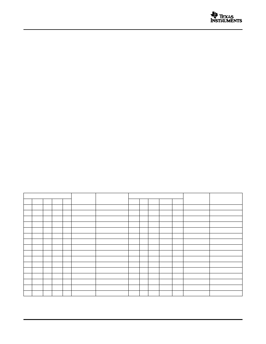
The
5-bit
Digital-to-Analog
Converter
(DAC)
is
through a resistor or a divider network.
programmed according to
Table 1
.The COMMAND
VREF: This pin provides an accurate 5V reference
voltage is always active as long as the UCC3882 VIN
and is internally short circuit current limited. VREF
pin is above the undervoltage lockout voltage. For the
powers the D/A Converter and also provides a
3882, the output gate drives GATEHI and GATELO
threshold voltage for the UVLO comparator. For best
are disabled at certain DAC codes, as shown in
reference stability, bypass VREF directly to GND with
Table 1
. Disabling the gate drives disables the power
a low ESR, low ESL capacitor of at least 0.01
µ
F.
supply. For the 3882 -1, the GATEHI and GATELO
drives are enabled for all DAC codes. For a given
VSNS: This pin is connected to the system output
code, the power supply output regulates at the
voltage through a low pass R-C filter. When the
corresponding COMMAND voltage.
voltage on VSNS rises above or falls below the
COMMAND voltage by 9%, the PWRGD output is
driven low to reset the microprocessor. When the
voltage on VSNS rises above the COMMAND voltage
by 17.5%, the OVP comparator disables the GATEHI
Table 1. Programming the Command Voltage for the UCC3882
Digital Command
Command
GATEHI/GATELO
Digital Command
Command
GATEHI/GATELO
Voltage
Status
Voltage
Status
D4
D3
D2
D1
D0
D4
D3
D2
D1
D0
0
1
1
1
1
1.300
Note 1 ?
1
1
1
1
1
2.000
Note 1 ?
0
1
1
1
0
1.350
Note 1 ?
1
1
1
1
0
2.100
Enabled
0
1
1
0
1
1.400
Note 1 ?
1
1
1
0
1
2.200
Enabled
0
1
1
0
0
1.450
Note 1 ?
1
1
1
0
0
2.300
Enabled
0
1
0
1
1
1.500
Note 1 ?
1
1
0
1
1
2.400
Enabled
0
1
0
1
0
1.550
Note 1 ?
1
1
0
1
0
2.500
Enabled
0
1
0
0
1
1.600
Note 1 ?
1
1
0
0
1
2.600
Enabled
0
1
0
0
0
1.650
Note 1 ?
1
1
0
0
0
2.700
Enabled
0
0
1
1
1
1.700
Note 1 ?
1
0
1
1
1
2.800
Enabled
0
0
1
1
0
1.750
Note 1 ?
1
0
1
1
0
2.900
Enabled
0
0
1
0
1
1.800
Enabled
1
0
1
0
1
3.000
Enabled
0
0
1
0
0
1.850
Enabled
1
0
1
0
0
3.100
Enabled
0
0
0
1
1
1.900
Enabled
1
0
0
1
1
3.200
Enabled
0
0
0
1
0
1.950
Enabled
1
0
0
1
0
3.300
Enabled
0
0
0
0
1
2.000
Enabled
1
0
0
0
1
3.400
Enabled
0
0
0
0
0
2.050
Enabled
1
0
0
0
0
3.500
Enabled
6

www.ti.com
APPLICATION INFORMATION
Synchronous Switching Delay Time
Using an External Schottky Diode in Parallel
Programming the Oscillator
UCC3882/-1
SLUS294A ≠ MARCH 1999 ≠ REVISED OCTOBER 2005
This IC is intended to be used in a high performance
For convenience, values are shown in
Table 1
for
power supply to power the PentiumÆ II or a similar
nominal frequencies from 100 kHz to 700 kHz using
processor.
Figure 1
shows a typical power supply
standards resistors and capacitor values.
application circuit which converts +5V to lower
voltages required by the PentiumÆII Processor.
Table 2. Programming Standard Frequencies
FREQUENCY
R
T
C
T
(kHz)
(k
)
(pF)
100
14.7
5600
Figure 2
shows that the fundamental difference
between a Buck and a Synchronous Buck regulator is
200
11.0
3900
the use of a MOSFET rather than a Schottky diode
300
10.5
2700
as the low side or free-wheeling switch.
400
11.3
1800
In order to maintain safe and efficient operation of a
500
12.7
1200
Synchronous Buck regulator, both MOSFETs, Q1 and
600
10.7
1200
Q2, should never be turned on at the same time.
700
11.0
1000
Having both MOSFETs on at the same time results in
cross conduction, which can result in excessively high
An excessively long delay time between gate drive
power dissipation in one or both MOSFETs. The
signals, or a delay time that is too small, will result in
UCC3882 has a built in delay between the turn OFF
a inefficient power supply design. The third step in
of one MOSFET and the turn ON of the other
programming the oscillator is to observe the actual
MOSFET. This delay is a controlled delay between
circuit waveforms to insure that the delay is optimal.
the GATEHI and GATELO drive outputs and is
The designer should vary R
T
and C
T
accordingly to
programmable by the selection of the resistor R
T
.
adjust the delay time and to program the proper
Controlling the delay between the gate drive outputs
oscillator frequency.
is only part of the solution. The power supply
designer
must
also
understand
intrinsic
delays
involving MOSFET turn on, turn off, rise and fall times
With the Low Side MOSFET
in order to insure that there is no cross conduction.
The purpose of using a synchronous buck regulator is
It is recommended that a value between 10 k
and
to substitute a low voltage drop MOSFET in place of
15 k
be used for R
T
, which minimizes the delay and
a Schottky diode as the low side switch. An external
can result in the highest efficiency operation. A higher
Schottky diode may still be required however, in order
value of R
T
will result in a larger delay between the
to reduce the losses due to the reverse recovery of
MOSFET Gate transitions. R
T
should be between 10
the low-side MOSFET body diode.
Figure 4
illustrates
k
minimum and 50 k
maximum.
the effects on power losses due to the non-ideal
nature of a typical MOSFET body diode. IRM is the
peak recovery current of the body diode of Q2 and
I
LOUT
is the current of the output inductor. Using a
The first step in programming the oscillator is
parallel Schottky diode can reduce these losses and
choosing the value of R
T
as described above. The
increase circuit efficiency. The size of the diode
second step is to program the frequency according to
should be increased as a function of load current,
the curves shown in
Figure 3
, by choosing the
input voltage, and operating frequency. The diode
appropriate capacitor value.ransitions. R
T
should be
should be as close to the lower MOSFET, Q2, as
between 10 k
minimum and 50 k
maximum.
possible, to reduce stray inductance.
7

www.ti.com
UDG-97048-1
V
CC
P
5 V
IN
C1
1500
µ
F
C2
1500
µ
F
C3
1500
µ
F
C20
1500
µ
F
Q1
IRL3103
C4
4.7
µ
F
Q2
IRL3103D1
L1
1.6
µ
H
R9
3.3
R10
3.3
R1
0.005
C5
1500
µ
F
C6
1500
µ
F
C7
1500
µ
F
C8
1500
µ
F
C9
1500
µ
F
C10
0.1
µ
F
R2
10 K
C14
0.01
µ
F
VREF
R8
10 K
C18
1500 pF
C19
220 pF
R7
5.6 K
C11
0.1
µ
F
R
T
10 k
C
T
3900 pF
F SWITCH = 225 kHz
R3
5.62 K
R5
365 k
C17
68 pF
R6
100 K
C13
0.01
µ
F
C12
0.01
µ
F
C15
0.1
µ
F
PWRGD
12 V
IN
VID0
VID1
VID2
VID3
VID4
ISHARE
OUTEN
U1
GND
D0
D1
NC
D2
D3
D4
COMMAND
VCRV1
GATE1
EN
COMP
VFB
UCC3882
VSNS
PWRGD
NC
CAM
CAO
ISOUT
IS+
IS-
VIN
VDRV2
GATE2
PGND
RT
CT
28
27
26
25
24
23
22
21
20
19
18
17
16
15
14
13
12
11
10
9
8
7
6
5
4
3
2
1
ISC
+
1.37 V
RSENSE
16
(1)
RSENSE
+
1.37 V
ISC
16
(2)
UCC3882/-1
SLUS294A ≠ MARCH 1999 ≠ REVISED OCTOBER 2005
Figure 1. Application Circuit ≠ PentiumÆ II Power Supply
The UCC3882 incorporates short circuit current
Choosing R
SENSE
to Set the Current Limit
foldback, as shown in
Figure 6
. When the output of
the power supply is short circuited, the output voltage
R
SENSE
is chosen to limit the maximum (short circuit)
falls. When the output voltage reaches 1/2 of its
current of the power supply. The short circuit current
nominal voltage (COMMAND/ 2) then the output
equation for the UCC3882 is:
current is reduced. This feature reduces the amount
of current in the MOSFETs and capacitors, and
insures high reliability.
and therefore, the value of the sense resistor, for a
chosen short circuit current is:
The short circuit current limit does vary slightly as a
function of the switching regulator's output inductor
value and operating frequency because a high value
of ripple current will reduce the average short circuit
current limit.
Figure 5
shows the variation in Isc given
common values for the UCC3882. The UCC3882 is
nominally configured so that a 0.005 m
resistor will
set the current limit to approximately 17A.
8

www.ti.com
UDG-97049
V
IN
Q1
R
G
D2
V
SOURCE
L
OUT
V
OUT
C
OUT
High
Drive
V
IN
Q1
V
SOURCE
L
OUT
V
OUT
C
OUT
Q2
R
G
R
G
High
Drive
Low
Drive
0
100
200
300
400
500
600
700
800
10
15
20
25
1 nF
1.2 nF
1.8 nF
2.7 nF
2.2 nF
3.9 nF
5.6 nF
f - Frequency - kHz
RT - Resistor Timing - kW
Choosing VDRVLO, VDRVHI and VIN,
UDG-97051
V
IN
V
SOURCE
V
OUT
C
OUT
Q1
L
OUT
High
Drive
R
G
Q2 Body
Diode
I
LOUT + IRM
Waveforms Without Reverse Recovery
Waveforms Including Reverse Recovery
Characteristics
V
SOURCE
Excess Losses Due
to Reverse Recovery
Characteristics in
Body Diode and
MOSFET Q1
I
LOUT
IRM
T
RR
T
A
T
B
DRAIN
CURRENT
DIODE
CURRENT
BODY
DIODE
LOSSES
Q1
LOSSES
Area Under
This Curve
Is Q
RR
I
LOUT
Input Capacitors
UCC3882/-1
SLUS294A ≠ MARCH 1999 ≠ REVISED OCTOBER 2005
capability
and
their
voltage
rating.
The
input
capacitors must handle virtually all of the RMS
current at the switching frequency, even if the circuit
does not have an input inductor. The switching
current in the input capacitors appears as shown in
Figure 7
.
Aluminum or tantalum capacitors can be used. The
amount of RMS current in an Electrolytic capacitor
has a strong impact on the reliability and lifetime of
the capacitor. Other factors which affect the life of an
input capacitor are internal heat rise, external airflow,
the amount of time that the circuit operates at
maximum current and the operating voltage. The
curves in
Figure 8
show the RMS current handled by
the total input capacitance in typical VRM circuits
powered from 5 V or from 12 V.
Figure 2. Buck vs Synchronous Buck Regulator
Figure 3. Programming UCC3882
Oscillator Frequency
The UCC3882 requires a nominal 12V input supplied
at VIN. VDRVLO and VDRVHI can be set to any
Figure 4. Effects of Reverse Recovery in a
voltage less than 18.5V, and may be set individually.
Synchronous Rectifier
A power supply deriving its power from +5V should
use +12V at the VDRVHI pin, but may use either +5V
or +12V depending on the drive requirements of the
synchronous low-side MOSFET. A power supply
deriving its power from +12V should use +18V at
VDRVHI in order to provide adequate voltage (6 V)
gate drive to the high-side MOSFET. VIN must be
less than +15V.
The input capacitors are chosen primarily based on
their switching frequency RMS current handling
9

www.ti.com
4
4.5
5
5.5
6
6.5
400 kHz, 3 mH
200 kHz, 3 mH
300 kHz, 1.5 mH
400 kHz, 1.5 mH
200 kHz, 1.5 mH
13
14
15
16
17
18
19
20
Short Circuit Current - A
Resense - mW
0
1
2
3
4
5
6
7
8
9
10
V
IN
= 5 V, V
OUT
= 1.8 V
V
IN
= 5 V, V
OUT
= 2.8 V
V
IN
= 12 V, V
OUT
= 2.8 V
V
IN
= 12 V, V
OUT
= 1.8 V
10
11
12
13
14
15
16
17
18
19
20
Choose the type and number of the input capacitors based
on these curves by choosing the input voltage and nominal
output Voltage. Example: For a 5 V input, 1.8 V outout power
supply with a load of 15 Amperes, the input capacitors
ahould be chosen for 7.5 Amperes RMS current.
Load Current - A
RMS Current For Input Caps -
ARMS
Demonstration Kit Design and Performance
0
20
40
60
80
100
0
20
40
60
80
100
Short Circuit Current - %
Nominal VOUT - %
UDG-96216
D
∑
Ts
(I-D)
∑
Ts
V
IN
V
ON
V
REPPLE
0
I
C
I
OFF
RMS CAPACITOR CURRENT
I
ON
2
∑
D+I
OFF
2
∑
(I-D)
UCC3882/-1
SLUS294A ≠ MARCH 1999 ≠ REVISED OCTOBER 2005
Figure 5. Short Circuit Current Limit vs R
SENSE
for
Figure 8. Load Current vs RMS Current for Input
Various Frequency and Inductor Values
Capacitors ≠ PentiumÆ II Family
A demonstration circuit was built based on the
UCC3882 and utilizing an Intel VRM 8.1 form factor
connector. The schematic is shown in
Figure 9
and
the list of materials in
Table 3
. The circuit is
configured for the following operating parameters:
∑
Switching Frequency = 225 kHz
∑
Rated Output Current = 15 A
∑
Short Circuit Current = 17 A Nominal
∑
Output Voltage: 1.8 V to 2.8 V Configured by VID
Code.
∑
Airflow: 100 LFM
∑
Temperature: 0
∞
C to 60
∞
C
Figure 6. Short circuit Foldback Reduces Stress
∑
Regulation: Per Intel VRM 8.1 DC-DC Converter
on Circuit Components by Reducing Short Circuit
Design Guidelines
Current
Figure 17
≠
Figure 19
show the performance of the
circuit.
Figure 7. Input Capacitors Current Waveform
10

www.ti.com
UCC3882/-1
SLUS294A ≠ MARCH 1999 ≠ REVISED OCTOBER 2005
Table 3. List of Materials
REF
DESCRIPTION
PACKAGE
U1
Unitrode UCC3882 DAC/PWM
SOIC-28 WIDE
C01
Sanyo 6MV1500GX, 1500
µ
F, 6.3 V, Aluminum Electrolytic
10x20mm Radial Can
C02
Sanyo 6MV1500GX, 1500
µ
F, 6.3 V, Aluminum Electrolytic
10x20mm Radial Can
C03
Sanyo 6MV1500GX, 1500
µ
F, 6.3 V, Aluminum Electrolytic
10x20mm Radial Can
C04
Sprague/Vishay 595D475X0016A2B, 4.7
µ
F 16 V Tantalum
SPRAGUE Size A,
C05
Sanyo 6MV1500GX, 1500
µ
F, 6.3 V, Aluminum Electrolytic
10x20mm Radial Can
C06
Sanyo 6MV1500GX, 1500
µ
F, 6.3 V, Aluminum Electrolytic
10x20mm Radial Can
C07
Sanyo 6MV1500GX, 1500
µ
F, 6.3 V, Aluminum Electrolytic
10x20mm Radial Can
C08
Sanyo 6MV1500GX, 1500
µ
F, 6.3 V, Aluminum Electrolytic
10x20mm Radial Can
C09
Sanyo 6MV1500GX, 1500
µ
F, 6.3 V, Aluminum Electrolytic
10x20mm Radial Can
C10
0.10
µ
F Ceramic
1206 SMD
C11
0.10
µ
F Ceramic
1206 SMD
C12
0.01
µ
F Ceramic
0603 SMD
C13
0.01
µ
F Ceramic
0603 SMD
C14
0.01
µ
F Ceramic
0603 SMD
C15
0.10
µ
F Ceramic
1206 SMD
C17
68 pF NPO Ceramic
0603 SMD
C18
1000 pF Ceramic
0603 SMD
C19
220 pF NPO Ceramic
0603 SMD
C20
Sanyo 6MV1500GX, 1500
µ
F, 6.3 V, Aluminum Electrolytic
10x20mm Radial Can
CT
3900pF Ceramic
0603 SMD
J1
AMP 532956-7 40 Pin Connector
40 Pin
L1
Toroid T51-52C, 5 Turns #16AWG, 1.6
µ
H
Toroid
Q1
International Rectifier IRL3103, 30 V, 56 A
TO-220AB, layed down
Q2
International Rectifier IRL3103D1, 30 V, 56 A
TO-220AB, layed down
R01
5 m
, PCB Resistor
Copper Trace
R02
10 k
, 5%, 1/16 Watt
0603 SMD
R03
5.62 k
, 1%, 1/16 Watt
0603 SMD
R05
365 k
, 1%, 1/16 Watt
0603 SMD
R06
100 k
, 5%, 1/16 Watt
0603 SMD
R07
5.6 k
, 5%, 1/16 Watt
0603 SMD
R08
10 k
, 5%, 1/16 Watt
0603 SMD
R09
3.3
, 5%, 1/16 Watt
0603 SMD
R10
3.3
, 5%, 1/16 Watt
0603 SMD
11

www.ti.com
UDG-97140
V
CC
P
A10
B11
A12
B13
A14
B15
A16
B17
A18
B19
A20
A1
B1
A2
B2
A3
B10
A11
B12
A13
B14
A15
B16
A17
B18
A19
B20
B9 PWRGD
A4 12 V
IN
B4
A7 VIDO
B7 VID1
A7 VIDO
A8 VID2
B8 VID3
A9 VID4
A6 ISHARE
B6 OUTEN
B3 NC
A5 NC
B5 NC
5 V
IN
Q1
IRL3103
L1
1.6
µ
H
R1
0.005
C1
1500
µ
F
C2
1500
µ
F
C3
1500
µ
F
C20
1500
µ
F
C4
4.7
µ
F
Q2
IRL3103D1
C5
1500
µ
F
C6
1500
µ
F
C7
1500
µ
F
C8
1500
µ
F
C9
1500
µ
F
C10
0.1
µ
F
R10
3.3
R9
3.3
R2
10 k
C14
0.01
µ
F
C15
0.1
µ
F
R8
10 k
C18
1500 pF
C19
220 pF
R7
5.6 k
C11
0.1
µ
F
R
T
10 k
C
T
3900 pF
F
SWITCH = 225 kHz
R3
5.62 k
R5
365 k
C17
68 pF
R6
100 k
C13
0.01
µ
F
C12
0.01
µ
F
GND
D0
D1
NC
D2
D3
D4
VREF
COMMAND
VDRV1
GATE1
EN
COMP
VFB
U1
VSNS
PWRGD
NC
CAM
CAO
ISOUT
IS+
IS-
VIN
VDRV2
GATE2
PGND
RT
CT
UCC3882
28
27
26
25
24
23
22
21
20
19
18
17
16
15
14
13
12
11
10
9
8
7
6
5
4
3
2
1
UCC3882/-1
SLUS294A ≠ MARCH 1999 ≠ REVISED OCTOBER 2005
Figure 9. Reference Design ≠ UCC3882 5-Bit Synchronous Wectifier PWM Controller for the Intel
PentiumÆII Processor
12

www.ti.com
UCC3882/-1
SLUS294A ≠ MARCH 1999 ≠ REVISED OCTOBER 2005
Figure 10. Demo Board
Figure 11. COMP Silkscreen
Figure 12. COMP Side
Figure 13. GND Layer
Figure 14. PWR Layer
Figure 15. Solder Side
Figure 16. Drill Drawing
13

www.ti.com
50
55
60
65
70
75
80
85
90
95
Efficiency - %
0
1
2
3
4
5
6
7
8
9
P
o
w
e
r
D
i
s
s
i
p
a
t
i
o
n
-
W
0
5
10
15
DC Load Current - A
Power Dissipation
Efficiency
-5
-3
-1
1
3
5
0
2
4
6
8
10
12
14
16
Load Current - A
Voltage Regulation - %
UCC3882/-1
SLUS294A ≠ MARCH 1999 ≠ REVISED OCTOBER 2005
Figure 17. Transient Response to 15.2A Step Load Channel 2 Scale is 50 mV/A
Figure 18. 13. UCC3882 Demo Kit Efficiency
Figure 19. Load Regulation
14

PACKAGING INFORMATION
Orderable Device
Status
(1)
Package
Type
Package
Drawing
Pins Package
Qty
Eco Plan
(2)
Lead/Ball Finish
MSL Peak Temp
(3)
UCC3882DW-1
ACTIVE
SOIC
DW
28
20
Green (RoHS &
no Sb/Br)
CU NIPDAU
Level-2-260C-1 YEAR
UCC3882DW-1G4
ACTIVE
SOIC
DW
28
20
Green (RoHS &
no Sb/Br)
CU NIPDAU
Level-2-260C-1 YEAR
UCC3882DWTR-1
ACTIVE
SOIC
DW
28
1000 Green (RoHS &
no Sb/Br)
CU NIPDAU
Level-2-260C-1 YEAR
UCC3882PW
ACTIVE
TSSOP
PW
28
50
Green (RoHS &
no Sb/Br)
CU NIPDAU
Level-2-260C-1 YEAR
UCC3882PWTR-1
ACTIVE
TSSOP
PW
28
2000 Green (RoHS &
no Sb/Br)
CU NIPDAU
Level-2-260C-1 YEAR
UCC3882PWTR-1G4
ACTIVE
TSSOP
PW
28
2000 Green (RoHS &
no Sb/Br)
CU NIPDAU
Level-2-260C-1 YEAR
(1)
The marketing status values are defined as follows:
ACTIVE: Product device recommended for new designs.
LIFEBUY: TI has announced that the device will be discontinued, and a lifetime-buy period is in effect.
NRND: Not recommended for new designs. Device is in production to support existing customers, but TI does not recommend using this part in
a new design.
PREVIEW: Device has been announced but is not in production. Samples may or may not be available.
OBSOLETE: TI has discontinued the production of the device.
(2)
Eco
Plan
-
The
planned
eco-friendly
classification:
Pb-Free
(RoHS)
or
Green
(RoHS
&
no
Sb/Br)
-
please
check
http://www.ti.com/productcontent
for the latest availability information and additional product content details.
TBD: The Pb-Free/Green conversion plan has not been defined.
Pb-Free (RoHS): TI's terms "Lead-Free" or "Pb-Free" mean semiconductor products that are compatible with the current RoHS requirements
for all 6 substances, including the requirement that lead not exceed 0.1% by weight in homogeneous materials. Where designed to be soldered
at high temperatures, TI Pb-Free products are suitable for use in specified lead-free processes.
Green (RoHS & no Sb/Br): TI defines "Green" to mean Pb-Free (RoHS compatible), and free of Bromine (Br) and Antimony (Sb) based flame
retardants (Br or Sb do not exceed 0.1% by weight in homogeneous material)
(3)
MSL, Peak Temp. -- The Moisture Sensitivity Level rating according to the JEDEC industry standard classifications, and peak solder
temperature.
Important Information and Disclaimer:The information provided on this page represents TI's knowledge and belief as of the date that it is
provided. TI bases its knowledge and belief on information provided by third parties, and makes no representation or warranty as to the
accuracy of such information. Efforts are underway to better integrate information from third parties. TI has taken and continues to take
reasonable steps to provide representative and accurate information but may not have conducted destructive testing or chemical analysis on
incoming materials and chemicals. TI and TI suppliers consider certain information to be proprietary, and thus CAS numbers and other limited
information may not be available for release.
In no event shall TI's liability arising out of such information exceed the total purchase price of the TI part(s) at issue in this document sold by TI
to Customer on an annual basis.
PACKAGE OPTION ADDENDUM
www.ti.com
19-Oct-2005
Addendum-Page 1

IMPORTANT NOTICE
Texas Instruments Incorporated and its subsidiaries (TI) reserve the right to make corrections, modifications,
enhancements, improvements, and other changes to its products and services at any time and to discontinue
any product or service without notice. Customers should obtain the latest relevant information before placing
orders and should verify that such information is current and complete. All products are sold subject to TI's terms
and conditions of sale supplied at the time of order acknowledgment.
TI warrants performance of its hardware products to the specifications applicable at the time of sale in
accordance with TI's standard warranty. Testing and other quality control techniques are used to the extent TI
deems necessary to support this warranty. Except where mandated by government requirements, testing of all
parameters of each product is not necessarily performed.
TI assumes no liability for applications assistance or customer product design. Customers are responsible for
their products and applications using TI components. To minimize the risks associated with customer products
and applications, customers should provide adequate design and operating safeguards.
TI does not warrant or represent that any license, either express or implied, is granted under any TI patent right,
copyright, mask work right, or other TI intellectual property right relating to any combination, machine, or process
in which TI products or services are used. Information published by TI regarding third-party products or services
does not constitute a license from TI to use such products or services or a warranty or endorsement thereof.
Use of such information may require a license from a third party under the patents or other intellectual property
of the third party, or a license from TI under the patents or other intellectual property of TI.
Reproduction of information in TI data books or data sheets is permissible only if reproduction is without
alteration and is accompanied by all associated warranties, conditions, limitations, and notices. Reproduction
of this information with alteration is an unfair and deceptive business practice. TI is not responsible or liable for
such altered documentation.
Resale of TI products or services with statements different from or beyond the parameters stated by TI for that
product or service voids all express and any implied warranties for the associated TI product or service and
is an unfair and deceptive business practice. TI is not responsible or liable for any such statements.
Following are URLs where you can obtain information on other Texas Instruments products and application
solutions:
Products
Applications
Amplifiers
amplifier.ti.com
Audio
www.ti.com/audio
Data Converters
dataconverter.ti.com
Automotive
www.ti.com/automotive
DSP
dsp.ti.com
Broadband
www.ti.com/broadband
Interface
interface.ti.com
Digital Control
www.ti.com/digitalcontrol
Logic
logic.ti.com
Military
www.ti.com/military
Power Mgmt
power.ti.com
Optical Networking
www.ti.com/opticalnetwork
Microcontrollers
microcontroller.ti.com
Security
www.ti.com/security
Telephony
www.ti.com/telephony
Video & Imaging
www.ti.com/video
Wireless
www.ti.com/wireless
Mailing Address:
Texas Instruments
Post Office Box 655303 Dallas, Texas 75265
Copyright
2005, Texas Instruments Incorporated