 | –≠–ª–µ–∫—Ç—Ä–æ–Ω–Ω—ã–π –∫–æ–º–ø–æ–Ω–µ–Ω—Ç: K11044TL | –°–∫–∞—á–∞—Ç—å:  PDF PDF  ZIP ZIP |
May, 1998 TOKO, Inc.
Page 1
TK11044
ADVANCED INFORMATION
TK11044
TEMPERATURE SENSOR IC
FEATURES
s
Linear Output Voltage 10 mV/
∞
C Output
s
2.4 to 8.0 Volt Supply Range
s
Miniature Package (SOT-23L)
s
Minimum External Parts Count
s
Low Power Consumption
APPLICATIONS
s
Home and Industrial Thermostats
s
Automotive Climate Control
s
Battery Charger Temperature Monitor
s
Notebook Computer Temperature Monitor
s
Electronic Thermometers
s
Fish Finder Water Temperature
s
Industrial Process Controllers
s
Home Appliance Temperature Control
BLOCK DIAGRAM
ORDERING INFORMATION
TAPE/REEL CODE
TL: Tape Left
Tape/Reel Code
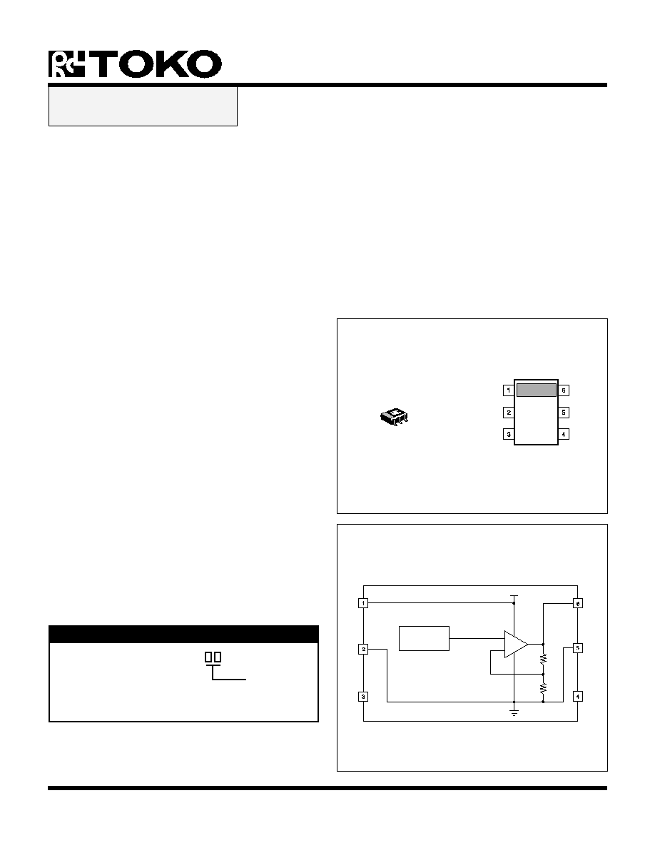
TK11044M-1
GND
VCC
NC
VOUT
NC
GND
20P
TEMPERATURE
DETECTION
CIRCUIT
GND
NC
GND
VCC
VOUT
VCC
+
-
NC
Note: Both GND pins must connect to GND
DESCRIPTION
The TK11044 is a temperature sensor IC with a linear
output of 10 mV/
∞
C over the range of -25 to + 105
∞
C. Its
wide operating voltage range of 2.4 to 8.0 volts makes it
suitable for a number of applications requiring accurate
temperature control, such as electronic thermostats for
climate control, refrigerators, and industrial process controls.
A typical application is to make a digital representation of
temperature with an A/D converter, or to make a thermal
detector with a comparator.
The TK11044 has a compensation pin for a 0.1
µ
F capacitor
that insures stability over the IC's operating temperature
range.
The TK11044 is available in a miniature SOT 23L-6 surface
mount package.
ADVANCED
INFORMATION
Page 2 May, 1998 TOKO, Inc.
TK11044
ADVANCED INFORMATION
SYMBOL
PARAMETER
TEST CONDITIONS
MIN
TYP
MAX
UNITS
V
OUT
Output Voltage
T
A
= 25
∞
C
965
995
1025
mV
T
A
= 85
∞
C
1573
1613
1653
mV
T
A
= -25
∞
C
480
mV
T
C
Temperature Coefficient
T
A
= 25
∞
C to 85
∞
C
9.5
10.3
11.1
mV/
∞
C
Line Reg
Line Regulation
V
CC
= 3 V to 5 V
-20
-5
20
mV
Load Reg
Load Regulation
I
OUT
= 0
µ
A to 400
µ
A
3
20
mV
I
CC
Supply Current
T
A
= 25
∞
C
160
200
µ
A
I
OUT
Output Current
V
OUT
20 mV
400
µ
A
Supply Voltage ......................................................... 12 V
Operating Voltage ............................................ 2.4 to 8 V
Power Dissipation (Note 1) ................................ 200 mW
Junction Temperature ........................................... 150
∞
C
ABSOLUTE MAXIMUM RATINGS
TK11044 ELECTRICAL CHARACTERISTICS
Test Conditions: V
CC
=
3.0 V, I
OUT
= 0
µ
A, T
A
= 25
∞
C, unless otherwise specified.
Note 1: Power dissipation is 200 mW when mounted as recommended. Derate at 1.6 mW/
∞
C for operation above 25
∞
C.
Storage Temperature Range ................... -55 to +150
∞
C
Operating Temperature Range ................. -25 to +105
∞
C
Lead Soldering Temp. (10 s) ................................. 235
∞
C
May, 1998 TOKO, Inc.
Page 3
TK11044
ADVANCED INFORMATION
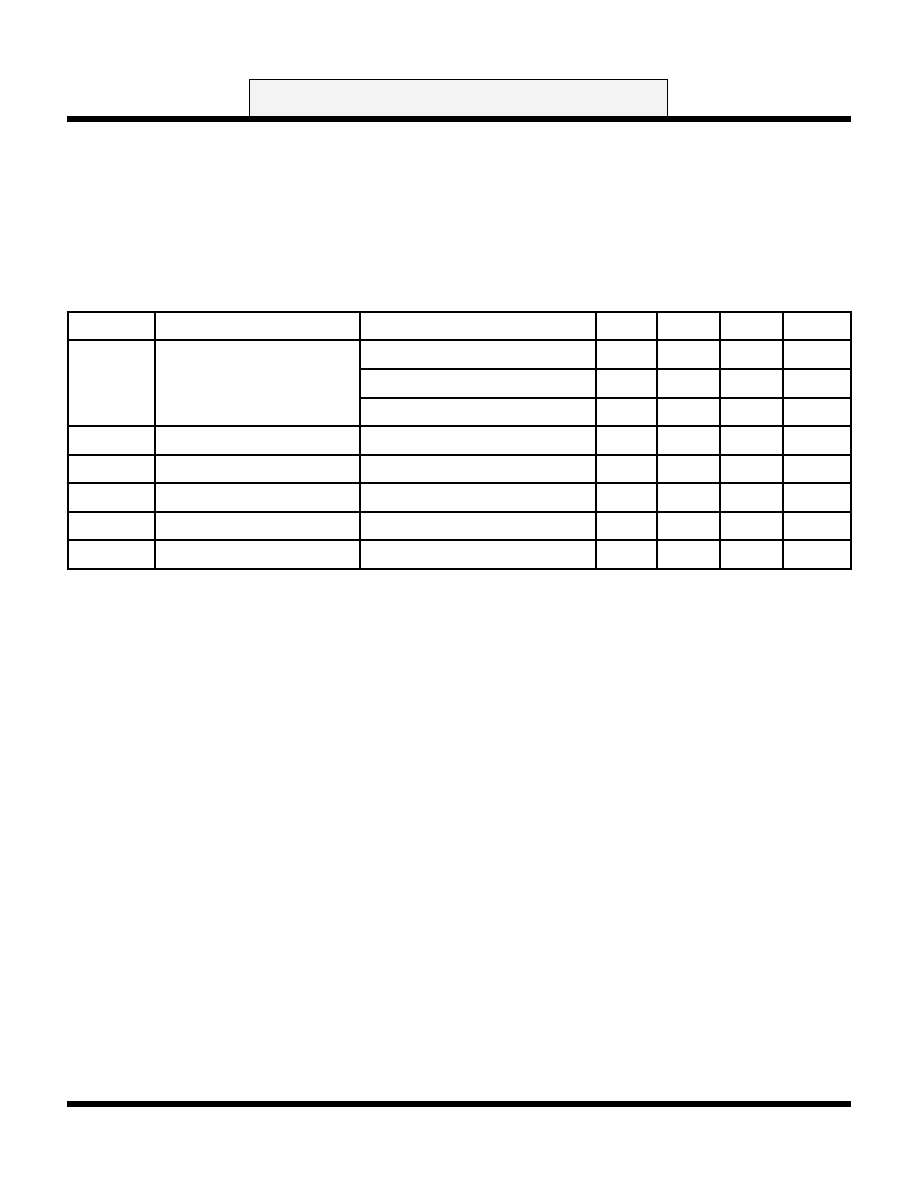
+
10 µF
VCC
VOUT
COUT
0.1 µF
V
OUT
(V)
1.0
2.0
OUTPUT VOLTAGE vs.
TEMPERATURE
80
120
TA (
∞
C)
0
40
0
-40
1.5
0.5
V
ERR
(
m
V)
0
16
LINEARITY ERROR vs.
TEMPERATURE
80
120
TA (
∞
C)
-16
40
0
-40
8
-8
I CC
(
µ
A)
160
200
INPUT CURRENT vs.
TEMPERATURE
80
120
TA (
∞
C)
120
40
0
-40
180
140
I CC
(
µ
A)
160
200
INPUT CURRENT vs.
INPUT VOLTAGE
8
10
VCC (V)
120
6
4
2
180
140
V
ERR
(
m
V)
0
20
LINE REGULATION
8
10
VCC (V)
-20
6
4
2
10
-10
V
ERR
(mV)
0
20
LOAD REGULATION
300
400
IOUT (µA)
-20
200
100
0
10
-10
TYPICAL PERFORMANCE CHARACTERISTICS
V
CC
= 3 V, I
OUT
= 0
µ
A, T
A
= 25
∞
C, unless otherwise specified.
TEST CIRCUIT
Page 4 May, 1998 TOKO, Inc.
TK11044
ADVANCED INFORMATION
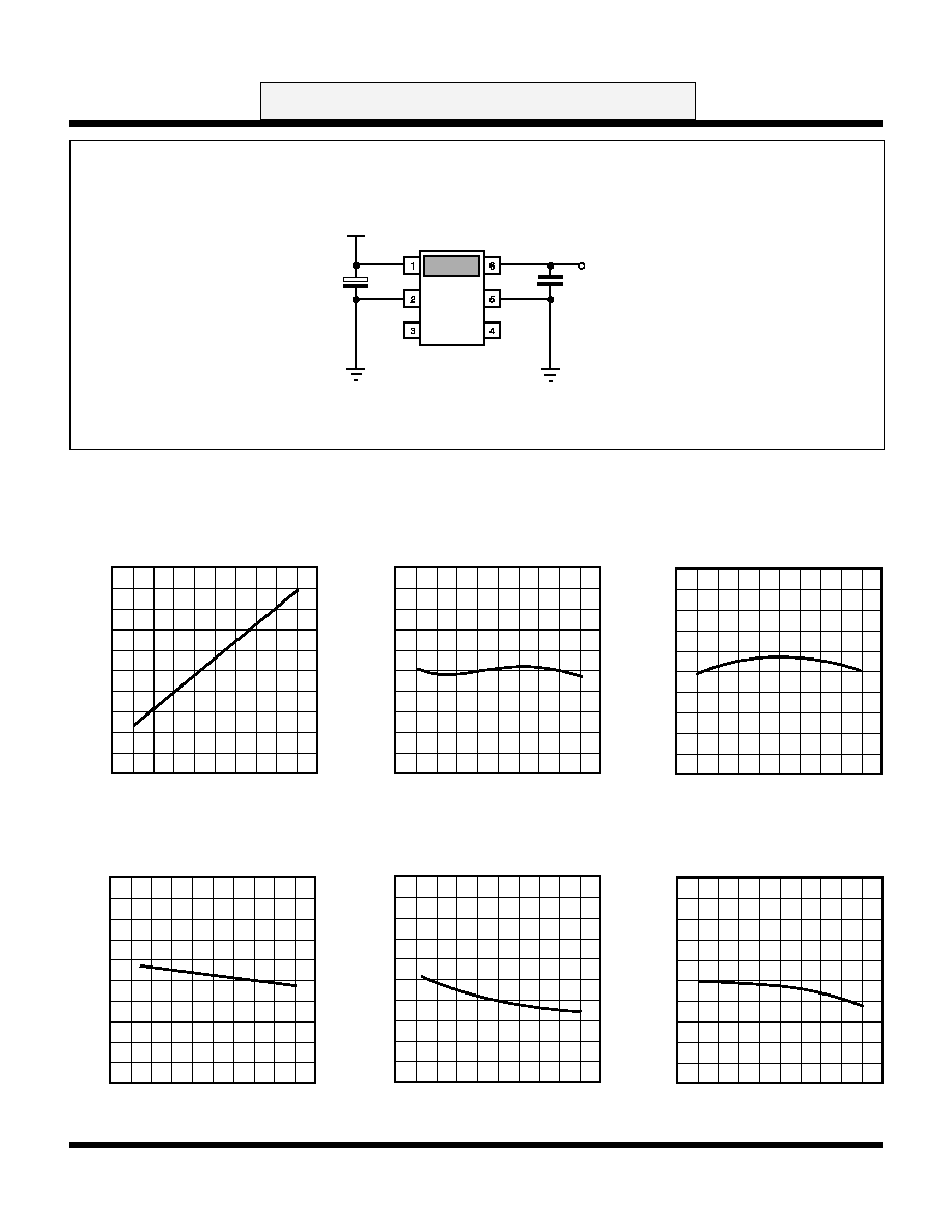
RR
(dB)
40
80
RIPPLE REJECTION RATIO A
10 k
100 k
f (Hz)
0
1 k
100
10
60
20
COUT = 0.1 µF
Vrr = 100mVrms
RR
(dB)
40
80
RIPPLE REJECTION RATIO B
10 k
100 k
f (Hz)
0
1 k
100
10
60
20
COUT = 0.1 µF
Vrr = 100mVrms
V
OUT
(V)
1.4
1.8
TEMPERATURE RESPONSE A
60
80
TIME (s)
1.0
40
20
0
1.6
1.2
25
∞
C TO 85
∞
C
V
OUT
(V)
0.8
1.2
TEMPERATURE RESPONSE B
60
80
TIME (s)
0.4
40
20
0
1.0
0.6
25
∞
C TO -30
∞
C
TYPICAL PERFORMANCE CHARACTERISTICS
V
CC
= 3 V, I
OUT
= 0
µ
A, T
A
= 25
∞
C, unless otherwise specified.

May, 1998 TOKO, Inc.
Page 5
TK11044
ADVANCED INFORMATION
SOT 23L-6
Marking Information
Marking
TK11044
44C
IC-???-TK11044
PACKAGE OUTLINE
The information furnished by TOKO, Inc. is believed to be accurate and reliable. However, TOKO reserves the right to make changes or improvements in the design, specification or manufacture of
its products without further notice. TOKO does not assume any liability arising from the application or use of any product or circuit described herein, nor for any infringements of patents or other
rights of third parties which may result from the use of its products. No license is granted by implication or otherwise under any patent or patent rights of TOKO, Inc.
TOKO AMERICA REGIONAL OFFICES
http://www.ictoko.com
Midwest Regional Office
Toko America, Inc.
1250 Feehanville Drive
Mount Prospect, Il 60056
Tel: (847) 297-0070
Fax: (847) 699-7864
Western Regional Office
Toko America, Inc.
2480 North First Street, Suite 260
San Jose, CA 95131
Tel: (408) 432-8281
Fax: (408) 943-9790
Eastern Regional Office
Toko America, Inc.
107 Mill Plain Road
Danbury, CT 06811
Tel: (203) 748-6871
Fax: (203) 797-1223
Semiconductor Technical Support
Toko Design Center
4755 Forge Road
Colorado Springs, CO 80907
Tel: (719) 528-2200
Fax: (719) 528-2375
© 1998 Toko, Inc.
All rights reserved
Printed in the USA
0.95
0.95
0.32
e
e
M
0.1
3.5
1.2
0.15
0.3
3.3
2.2
0.4
0.95
0.95
3.0
e
e
e1
0.6
1.0
Recommended Mount Pad
1
2
3
4
5
6
0 ~ 0.1
15
max
1.4 max
marking
+0.15
- 0.05
+0.3
- 0.1
+ 0.3
(3.4)
+0.15
- 0.05
Dimensions are shown in millimeters
Tolerance: x.x =
±
0.2 mm (unless otherwise specified)
5 PL
0.1