July 1999 TOKO, Inc.
Page 1
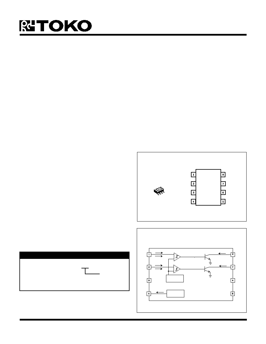
TK11052
GND
OUTPUT1
OUTPUT2
NC
INPUT2
INPUT1
VCC
VREF
FEATURES
s
Internal Temperature Sensor, Voltage Reference
and Two Comparators with
s
Temperature Threshold and Hysteresis Set by Only
Two External Resistors
s
Output Logic:
Low to High with Increasing Temp. by OUTPUT1
High to Low with Increasing Temp. by OUTPUT2
s
Very Wide Operating Supply Range
(V
CC
= 2.7 to 6.0 V)
s
Miniature Package (SOT23L-8)
s
Minimum External Parts Count
s
Low Power Consumption
s
Very Wide Temperature Range
BLOCK DIAGRAM
TK11052
DESCRIPTION
The TK11052 is an accurate temperature controller IC for
use over the -30 to +105
�
C temperature range. The
TK11052 monolithic bipolar integrated circuit contains a
temperature sensor, stable voltage reference and two
comparators, making the device very useful as an on/off
thermostat. Two external resistors easily set the sensing
temperature threshold and hysteresis of each thermostat.
Its wide operating voltage range of 2.7 to 6.0 V makes this
IC suitable for a number of applications requiring an
accurate thermostat.
The TK11052 is available in a miniature SOT23L-8 surface
mount package.
01S
-
+
TEMPERATURE
SENSOR
TC = 6.1 mV/
�
C
ISINK1
REFERENCE
VOLTAGE
Vref = 1.597 V
I
OUT
-
+
I
IB2
I
SH2
I
IB1
I
SH1
COMP2
COMP1
ISINK2
ORDERING INFORMATION
TAPE/REEL CODE
TL: Tape Left
Tape/Reel Code
TK11052MTL
THERMOSTAT IC
APPLICATIONS
s
Home and Industrial Thermostats
s
Home Appliance Temperature Control
s
Notebook Computer Temperature Monitor
s
Pentium Processor Temperature Monitor
s
Power Supply Overtemperature Protection
s
Copy Machine Overtemperature Protection
s
System Overtemperature Protection
Page 2
July 1999 TOKO, Inc.
TK11052
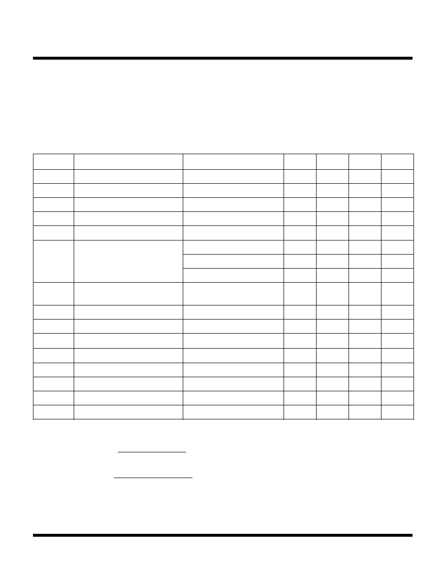
ABSOLUTE MAXIMUM RATINGS
Supply Voltage ......................................................... 10 V
Power Dissipation .............................................. 200 mW
Storage Temperature Range ................... -55 to +150
�
C
Operating Temperature Range ................. -30 to +105
�
C
Operating Voltage Range .............................. 2.7 to 6.0 V
Junction Temperature .......................................... 150
�
C
Lead Soldering Temperature (10 s) ..................... 235
�
C
TK11052 ELECTRICAL CHARACTERISTICS
Test conditions: T
A
= 25
�
C, V
CC
= 3.0 V, I
OUT
= 80
�
A, R
OUT1
= 300 k
, R
OUT2
= 300 k
,
unless otherwise specified.
Note 1: This spec. is an error between a temp. to which the comparator reverses and a set temp. The resistance values of R
a
, R
b
, R
c
, R
d
can be
calculated as follows:
R
a
or R
c
=
R
b
or R
d
=
Note 2: When V
TEMP
< INPUT1, OUTPUT1 > 2.8 V (C
LH
). When V
TEMP
> INPUT1, OUTPUT1 < 0.3 V (C
LL
).
When V
TEMP
< INPUT2, OUTPUT2 < 0.3 V (C
LL
). When V
TEMP
> INPUT2, OUTPUT2 > 2.8 V (C
LH
).
V
REF
x T
SM
x T
C
(0.4925 + T
SET
x T
C
) x I
SH
V
REF
x T
SH
x T
C
(V
REF
- 0.4925 - T
SET
x T
C
) x I
SH
L
O
B
M
Y
S
R
E
T
E
M
A
R
A
P
S
N
O
I
T
I
D
N
O
C
T
S
E
T
N
I
M
P
Y
T
X
A
M
S
T
I
N
U
I
C
C
t
n
e
r
r
u
C
y
l
p
p
u
S
C
:
1
T
U
O
H
L
C
:
2
T
U
O
,
L
L
0
8
2
0
5
3
A
�
V
f
e
r
e
g
a
t
l
o
V
e
c
n
e
r
e
f
e
R
)
4
n
i
P
(
7
9
5
.
1
V
I
T
U
O
V
(
t
n
e
r
r
u
C
t
u
p
t
u
O
f
e
r
)
)
4
n
i
P
(
V
m
2
1
<
g
e
R
d
a
o
L
0
8
0
0
5
A
�
g
e
R
e
n
i
L
V
(
n
o
i
t
a
l
u
g
e
R
e
n
i
L
f
e
r
)
V
C
C
)
4
n
i
P
(
V
6
o
t
V
3
=
9
-
0
9
+
V
m
g
e
R
d
a
o
L
V
(
n
o
i
t
a
l
u
g
e
R
d
a
o
L
f
e
r
)
I
T
U
O
)
4
n
i
P
(
A
�
0
0
5
o
t
A
�
0
=
3
2
1
V
m
V
P
M
E
T
)
l
a
n
r
e
t
n
i
(
r
o
s
n
e
S
e
r
u
t
a
r
e
p
m
e
T
T
A
C
�
5
2
=
5
4
6
V
m
T
A
C
�
5
8
=
1
1
0
1
V
m
T
A
C
�
0
=
5
.
2
9
4
V
m
T
C
t
n
e
i
c
i
f
f
e
o
C
e
r
u
t
a
r
e
p
m
e
T
)
l
a
n
r
e
t
n
i
(
T
A
C
�
5
8
o
t
C
�
0
=
1
.
6
C
�
/
V
m
T
R
R
E
r
o
r
r
E
e
r
u
t
a
r
e
p
m
e
T
l
a
t
o
T
T
A
)
1
e
t
o
N
(
C
�
5
8
o
t
C
�
0
=
0
.
4
-
0
0
.
4
C
�
C
H
L
l
e
v
e
L
h
g
i
H
t
u
p
t
u
O
r
o
t
a
r
a
p
m
o
C
)
2
e
t
o
N
(
8
.
2
V
C
L
L
l
e
v
e
L
w
o
L
t
u
p
t
u
O
r
o
t
a
r
a
p
m
o
C
I
K
N
I
S
)
2
e
t
o
N
(
A
�
0
0
5
3
.
0
V
I
1
B
I
1
t
n
e
r
r
u
C
s
a
i
B
t
u
p
n
I
C
:
1
T
U
O
H
L
0
5
-
0
0
5
A
n
I
1
H
S
1
t
n
e
r
r
u
C
t
e
S
s
i
s
e
r
e
t
s
y
H
C
:
1
T
U
O
L
L
9
.
0
5
3
.
1
8
.
1
A
�
I
2
B
I
2
t
n
e
r
r
u
C
s
a
i
B
t
u
p
n
I
C
:
2
T
U
O
L
L
0
5
-
0
0
5
A
�
I
2
H
S
2
t
n
e
r
r
u
C
t
e
S
s
i
s
e
r
e
t
s
y
H
C
:
2
T
U
O
H
L
9
.
0
5
3
.
1
8
.
1
A
�
I
K
N
I
S
t
n
e
r
r
u
C
k
n
i
S
t
u
p
t
u
O
C
L
L
)
8
n
i
P
,
7
n
i
P
(
,
V
3
.
0
0
1
0
0
5
A
�
July 1999 TOKO, Inc.
Page 3
TK11052
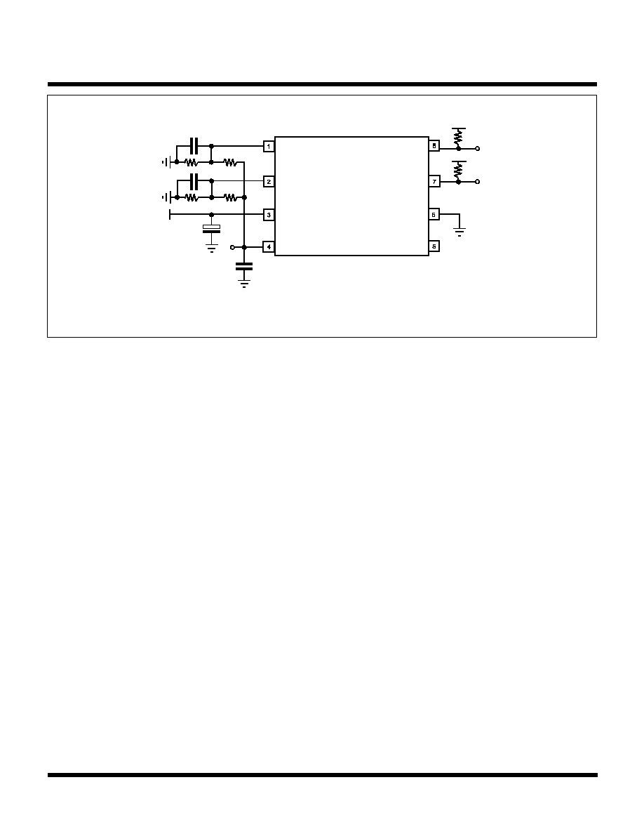
Note: For information on C
b
and C
d
, see Applications Hints Section.
V
CC
1 �F
Cref = 0.1 �F
V
ref
R
b
R
a
R
d
R
c
V
CC
V
CC
R
OUT1
R
OUT2
OUTP
OUTP
C
b
= 0.1 �F
C
d
= 0.1 �F
TEST CIRCUIT
Page 4
July 1999 TOKO, Inc.
TK11052
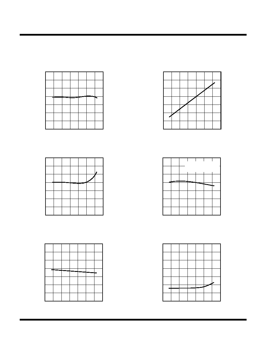
TYPICAL PERFORMANCE CHARACTERISTICS (CONT.)
T
A
= 25
�
C, V
CC
= 3 V, I
OUT
= 80
�
A, unless otherwise specified.
V
ref
(V)
1.58
1.62
REFERENCE VOLTAGE vs.
TEMPERATURE
TA (
�
C)
1.54
-25 0 25 50 75 100
1.60
1.56
1.64
V
TEMP
(V)
0.8
1.2
TEMPERATURE SENSOR vs.
TEMPERATURE
TA (
�
C)
0.2
-25 0 25 50 75 100
1.0
0.4
0.6
T
ERR
(
C)
0
2
TOTAL TEMPERATURE ERROR vs.
TEMPERATURE
TA (
�
C)
-3
-25 0 25 50 75 100
1
-2
-1
I CC
(
�
A)
270
SUPPLY CURRENT vs.
TEMPERATURE
TA (
�
C)
250
-25 0 25 50 75 100
280
260
290
300
OUTPUT1 = "H"
OUTPUT2 = "L"
I SH
(
�
A)
1.5
2.5
HYSTERESIS SET CURRENT vs.
TEMPERATURE
TA (
�
C)
0
-25 0 25 50 75 100
2.0
0.5
1.0
I IB
(
n
A)
3
5
INPUT BIAS CURRENT vs.
TEMPERATURE
TA (
�
C)
0
-25 0 25 50 75 100
4
1
2

July 1999 TOKO, Inc.
Page 5
TK11052
TYPICAL PERFORMANCE CHARACTERISTICS (CONT.)
T
A
= 25
�
C, V
CC
= 3 V, I
OUT
= 80
�
A, unless otherwise specified.
LINE
REG
(
m
V)
0
2
LINE REGULATION
VCC (V)
-2
3 4 5 6 7 8
1
-1
0
I CC
(V)
300
340
SUPPLY CURRENT vs.
SUPPLY VOLTAGE
VCC (V)
260
3 4 5 6 7 8
320
280
240
OUTPUT1 = "H"
OUTPUT2 = "L"
OUTPUT1
(V)
1.5
2.5
OUTPUT 1 vs. SUPPLY VOLTAGE
VCC (V)
0
0 0.5 1.0 1.5 2.0 2.5
2.0
1.0
0.5
when C
LH
OUTPUT1
(V)
1.5
2.5
OUTPUT 1 vs. SUPPLY VOLTAGE
VCC (V)
0.5
0 0.5 1.0 1.5 2.0 2.5
2.0
1.0
0
when CLL
OUTPUT2
(V)
1.5
2.5
OUTPUT 2 vs. SUPPLY VOLTAGE
VCC (V)
0
0 0.5 1.0 1.5 2.0 2.5
2.0
1.0
0.5
when CLH
OUTPUT2
(V)
1.5
2.5
OUTPUT 2 vs. SUPPLY VOLTAGE
VCC (V)
0.5
0 0.5 1.0 1.5 2.0 2.5
2.0
1.0
0
when CLL