Document Outline
- 3613c_4.pdf
- ˛ˇ
- ˛ˇ
- ˛ˇ
- ˛ˇ
- ˛ˇ
- ˛ˇ
- ˛ˇ
- ˛ˇ
- ˛ˇ
- ˛ˇ
- ˛ˇ
- 3613c_5.pdf
- 3613c_6.pdf
- 3613c_7.pdf
- 3613c_8.pdf
- 3613c_9.pdf
- 3613c_10.pdf
- 3613c_11.pdf

LED Lamps
LED Lamps
PRODUCT GUIDE
3
The following related catalog are also published on the website.
"LED Lamps Application Guide"
http://doc.semicon.toshiba.co.jp/noseek/us/buct/bcfm.htm
Related catalog on website
Surface-mount devices (SMDs): 68 products
∑ TL
H Series
∑ TL
E Series
∑ TL
U Series
High-blightness lead type: 231 products
∑ TL
H Series
∑ TL
E Series
∑ TL
U Series
∑ S4F42
Series
∑ S4F43
Series
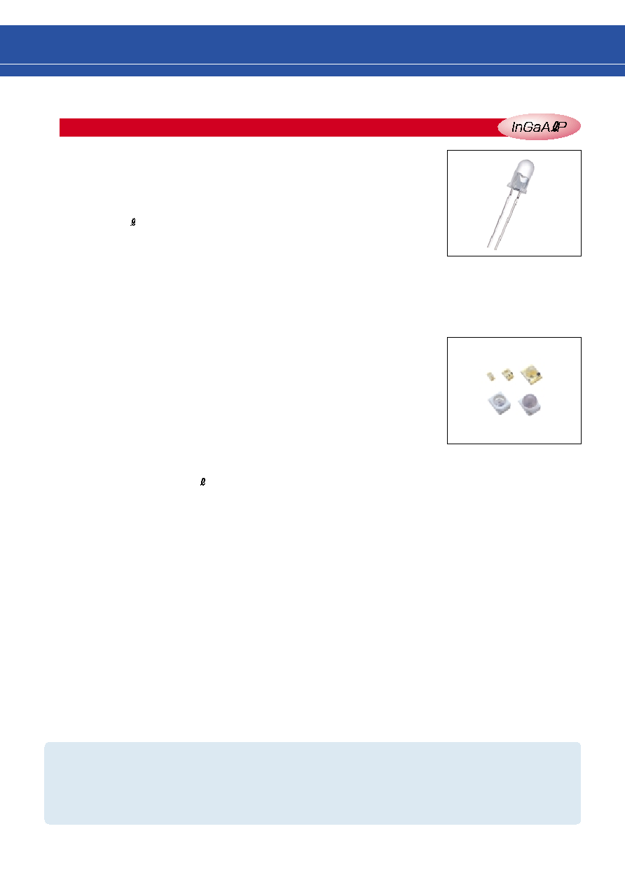
LED Lamp Family 299 products
q
products are mainly from the World's highest
luminosity level "TL
H Series" to general-purpose "TL
U Series"
q
Stopper lead type and straight lead type available. (for ¯5-mm type
only)
Suffix "P" indicates straight or stopper type.
(example: TL
E16TP is straight type.)
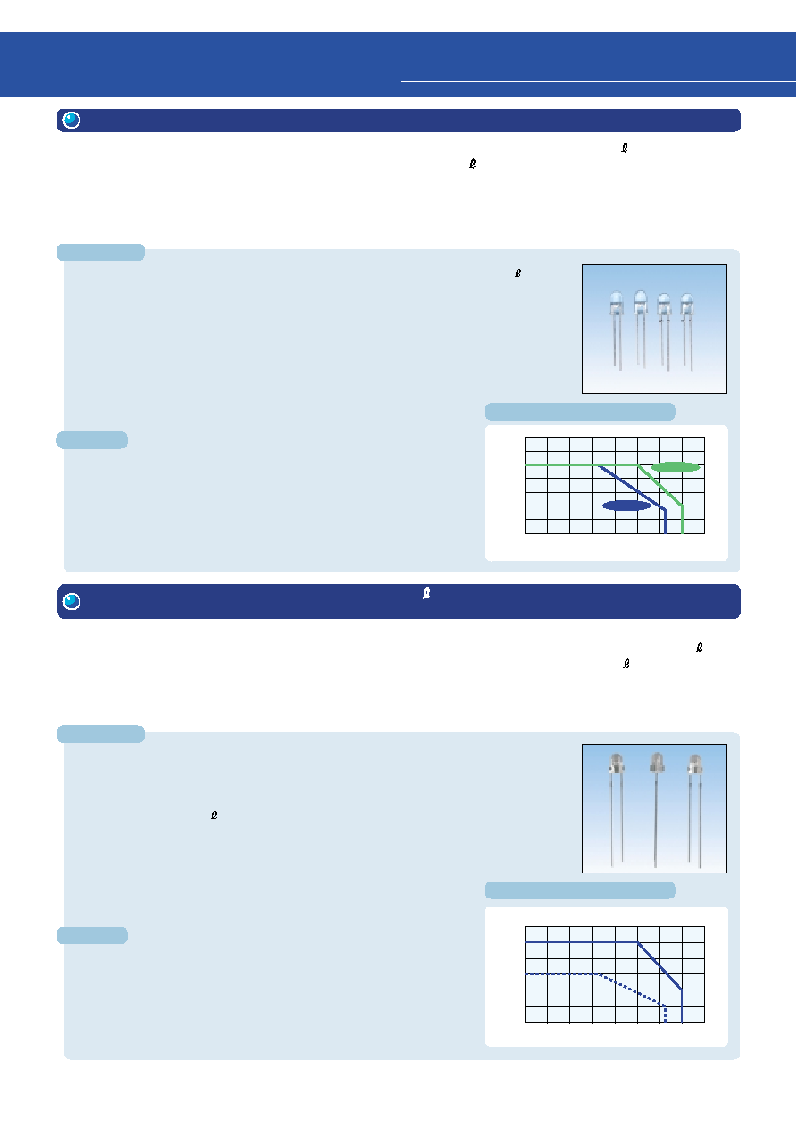
s
Toshiba Visible LED Lamp Family Outline
q
Package size: 1.6 x 0.8 mm
2.0 x 1.25 mm
3.2 x 2.4 mm (¯2 lens-top)
3.2 x 2.8 mm (flat type / ¯3 lens-top)
q
Four-element ( ) chip LEDs enable construction of low power
dissipation equipment.
q
Wider operating range: Topr = --40
∞
C to 100
∞
C
(TL
1100 Series, TL
1102 Series, S4F42
Series, S4F43
Series)
InGaA P
InGaA P
4
1
New Product Digest
Uses
LED information panels, indicators
The package specification in the product number for new TL
H Series
is now given as two digits instead of three as at present.
1. New TL
H Series (Ultra-High-Brightness ¯5-mm LED Lamp Series)
Features
Uses
Display light sources, information display boards, light sources for back-
lighting
50
40
30
20
10
0
-40
-20
0
40
60
100
20
80
120
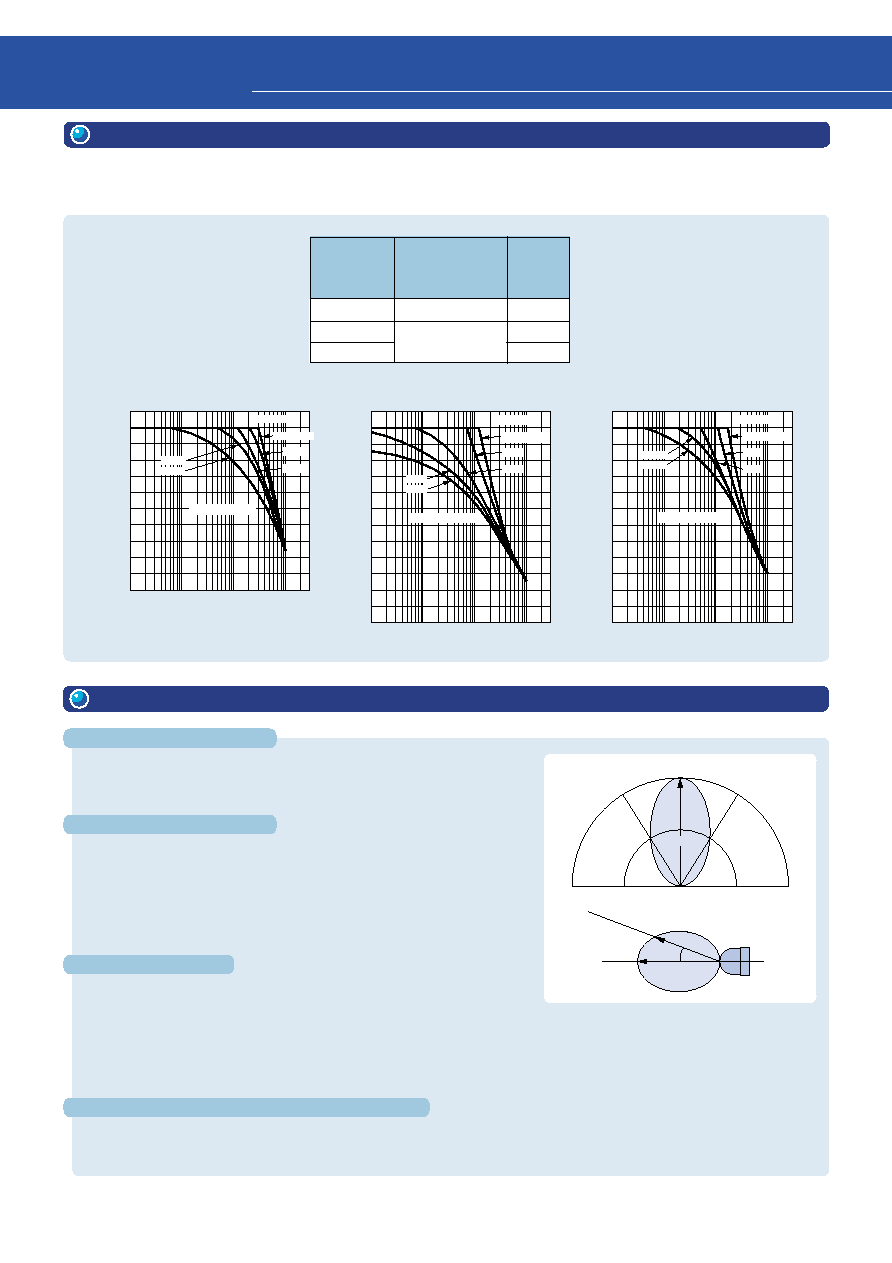
Solid line: TLRME68TG,TLYE68TG,TLGE68TG
Dotted line: TLSU268G
Ambient Temperature Ta (
∞
C)
Permissible Forward Current I
F
(mA)
10
20
30
40
50
60
-40
-20
0
40
60
100
20
80
120
Ambient Temperature Ta (
∞
C)
Permissible Forward Current I
F
(mA)
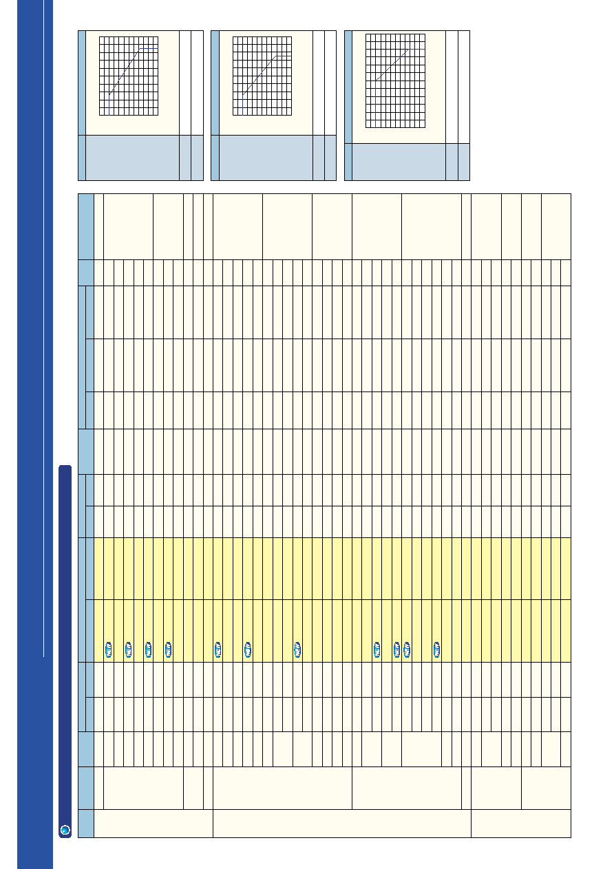
NEW H Series
Existing H Series
Derating Characteristics
Derating Characteristics
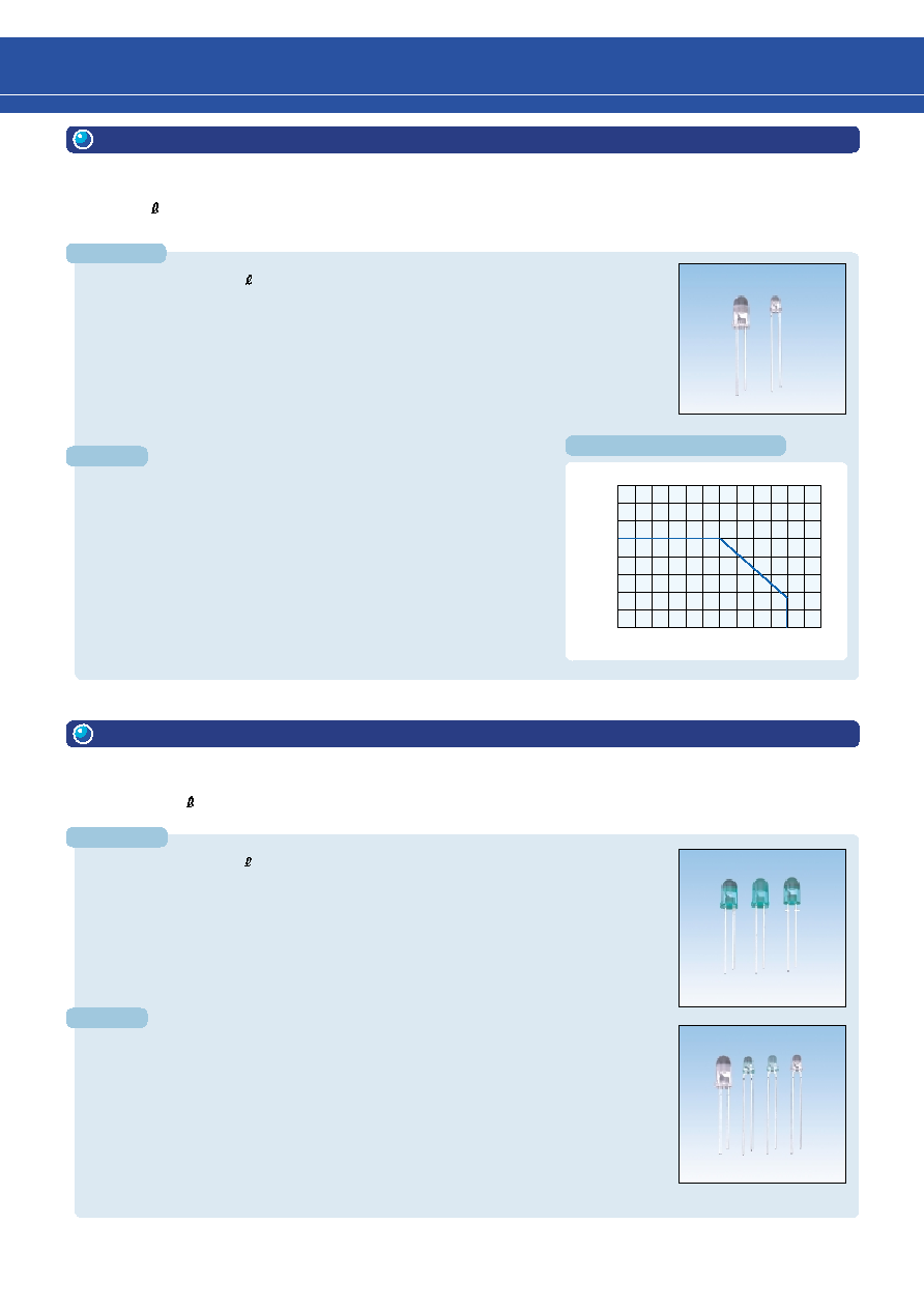
Using thin-film crystal growth technology to produce the ultra-bright light-emitting material , as well as a new
process and structure. Toshiba has developed a new line-up of ultra-bright LED lamps.
These new LED lamps emit ultra-bright light. Higher brightness can be achieved at high temperature owing to an
improved derating characteristic. The new series is effective in various applications such as outdoor LED information
panels, high-brightness indications and backlighting for displays.
InGaA P
InGaA P
Features
q
A brightness approximately 1.3 times that of the existing high-brightness TL
H
Series of LED lamps can be achieved (comparison conditions: IF = 20 mA, Ta = 25
∞
C,
same radiation pattern)
q
Sufficient current can be obtained, even at high temperature, owing to an improved derat-
ing characteristic. Thus, at Ta = 50
∞
C, brightness is approximately double that of the
existing TL
H Series.
q
High-brightness emission can be achieved even at low-current drive. Lowering the drive
current reduces product power dissipation.
q
Four types of ¯5-mm lens with various radiation patterns are available.
InGaA P
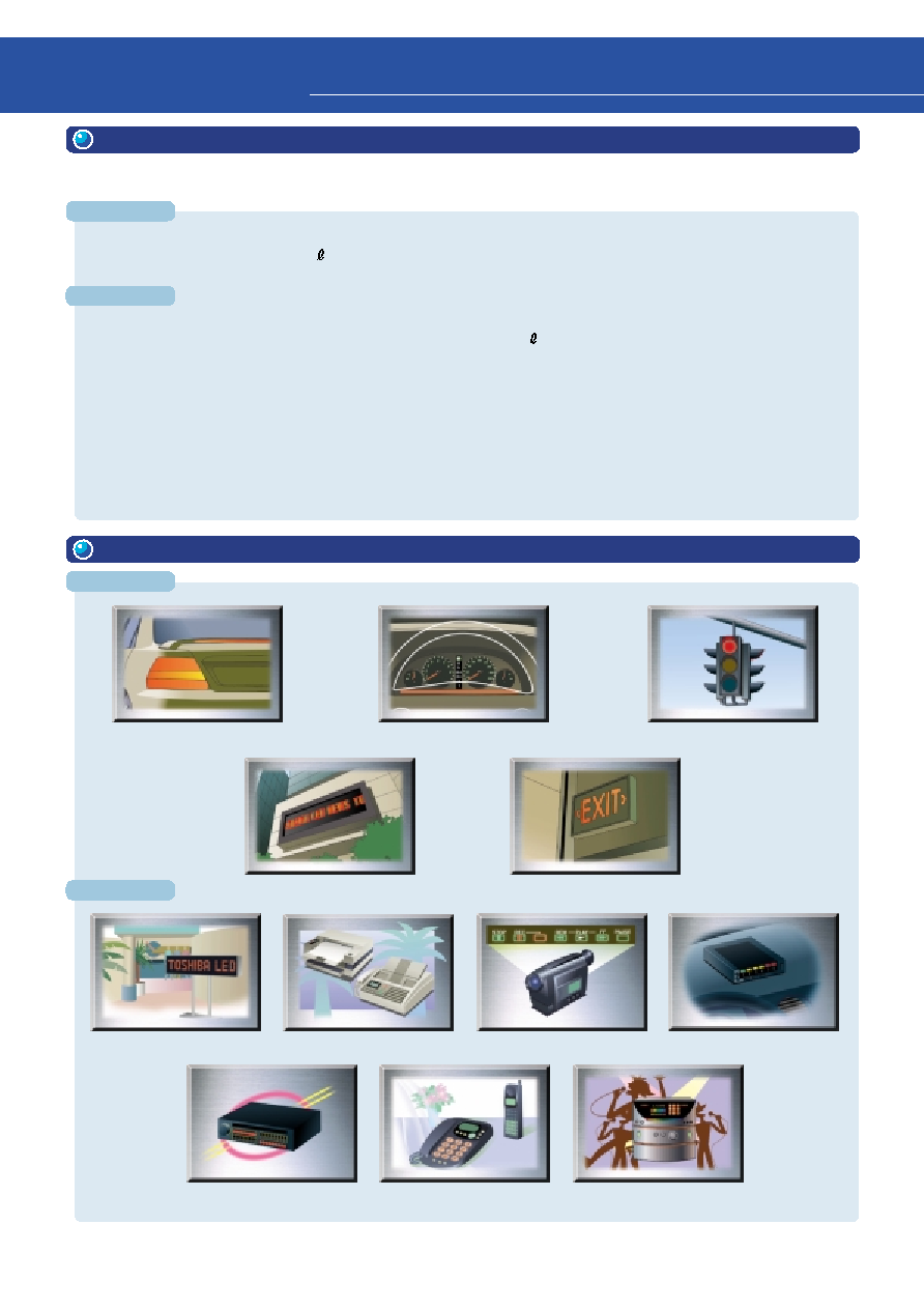
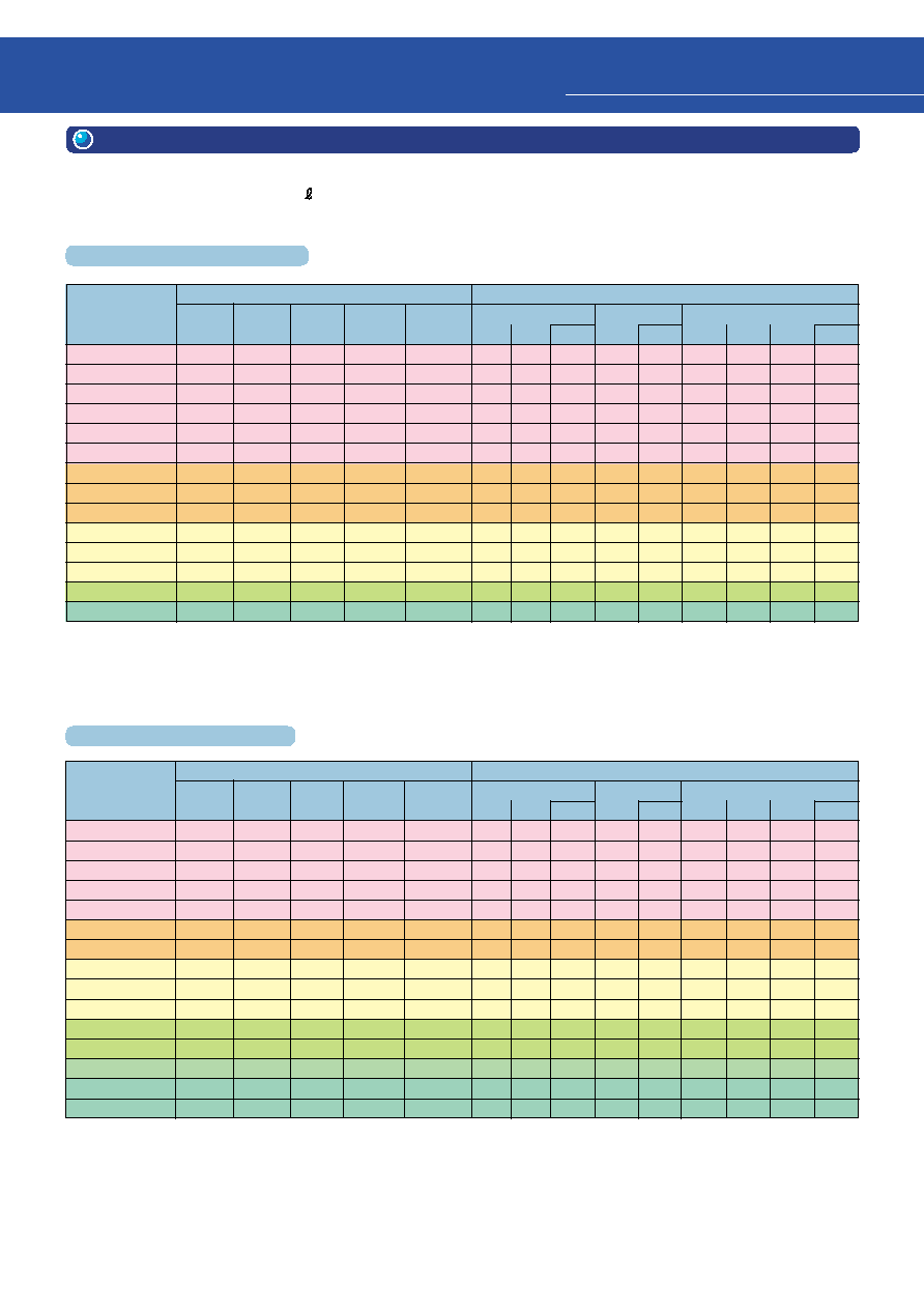
When products are selected for use in equipment, mountability is a key factor. Most devices are now mounted using
a high-speed surface mounter. To comply with this requirement, Toshiba has introduced a series of ¯3-mm LED
lamps which can be mounted flush with a PCB using a surface mounter. High-brightness , suitable for both
indoor and outdoor applications, is used as the emitting substance.
These new LED lamps can be used in a wide range of applications, such as LED information panels, low-power-
consumption indicators and high-brightness backlighting for displays.
InGaA P
InGaA P
q
Can be mounted flush with a PCB using a surface mounter.
This enables reduction in assembly costs and time, reduction in height of finished prod-
uct, and reduction of risk of damage due to finished products shifting during transporta-
tion.
q
High-brightness LEDs used
q
Transparent packages with wide viewing angle
q
Emitted colors: red (626 nm and 613 nm), yellow and green
q
Superior derating characteristics enable excellent high-brightness emission in high-
temperature environments.
q
Because high-brightness emission can be low, resulting in low power
consumption by the equipment as a whole.
InGaA P
2. TLRME68TG Series (Round ¯3-mm InGaA P LED Lamps Which Can Be
Mounted Flush with PCB
Using Surface Mounter)
5
Features
Uses
Features
Uses
Toshiba has added to its LED product line-up the TLFGE Series (of a color between those of the existing TLPGE and
TLGE Series) and the TLPYE Series (of a color between those of the existing TLGE and TLYE Series). High-bright-
ness , widely used in both indoor and outdoor applications, is used as the light-emitting material.
3. TLFGE / TLPYE Series with New Colors
q
High-brightness LED
q
Emitted colors: TLFGE Series (fresh green):
d = 565 nm (typ.)
TLPYE Series (pure yellow):
d = 580 nm (typ.)
q
High-brightness even at high temperature owing to improved derating characteristic
q
High-brightness emission even at low-current drive. Product power dissipation can be
reduced.
q
Four types of ¯5-mm and ¯3-mm lens with various radiation patterns are available.
Select a lens according to the intended application.
4. TLGU / TLPGU Series
Toshiba now offers a lead-type green U series. A brightness approximately five to eight times that of the Toshiba
general-purpose medium-brightness Series (which uses GaP as the light-emitting material) can be achieved. High-
brightness , widely used in both indoor and outdoor applications, is used as the light-emitting material.
q
High-brightness LED
q
Emitted colors: TLGU Series (green):
d = 571 nm
TLPGU Series (pure green):
d = 558 nm
q
High-brightness even at high temperature owing to improved derating characteristic
q
20 types of green and pure-green ¯5-mm and ¯3-mm oval lens with various radiation pat-
terns are available.
Select a lens according to the intended application.
Display light sources, information display boards, panel indicators
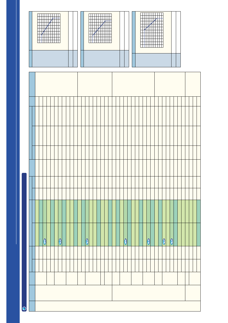
Derating Characteristics
Permissible Forward Current I
F
(mA)
Ambient Temperature Ta (
∞
C)
IF--Ta
80
60
40
20
0
0
20
40
60
80
100
120
Display light sources, information display boards, light sources for
backlighting
InGaA P
InGaA P
InGaA P
InGaA P
6
2
Overview
SMD type
Lead type
Lead type
Toshiba LED lamps feature higher brightness, multiple colors and many types of package.
Select LEDs for your applications as appropriate.
q
Miniature surface mount, upper-face emitting type
q
A wide product line-up by high luminosity four-element ( ) emitted-light devices
q
Can be used in automatic mounting.
q
Suitable for reflow soldering
q
Standard 1.6 x 0.8 mm type and 2 x 1.25 mm type
The original ¯2-mm lens-top type suitable for thin profile applications not possible with conventional lead
type LEDs
Select the best device for your own particular application.
q
Line-up of high-heat resistance type
Suitable for use in automobile backlight sorce
1. Features
2. Uses
Thin-electronic bulletin board
CHMSL
(Center High Mounted Stop Lamp)
Home/cellular telephone
FA equipment
(Programable control, etc.)
Message board
Security equipment
Light-emitting display
Traffic light
AV equipment
(Karaoke set, etc.)
OA equipment
Handy camera
Accessaries on dashboard
q
Colors are from red to pure green (total 10 colors).
q
Line-up of four-element ( ) compound semiconductors allows outdoor use.
q
Many types of package enable the user to select LED lamps to suit his or her application.
InGaA P
SMD type
InGaA P
7
What are four-element LEDs?
Wide market size for four-element LEDs
Merits of high-brightness LEDs
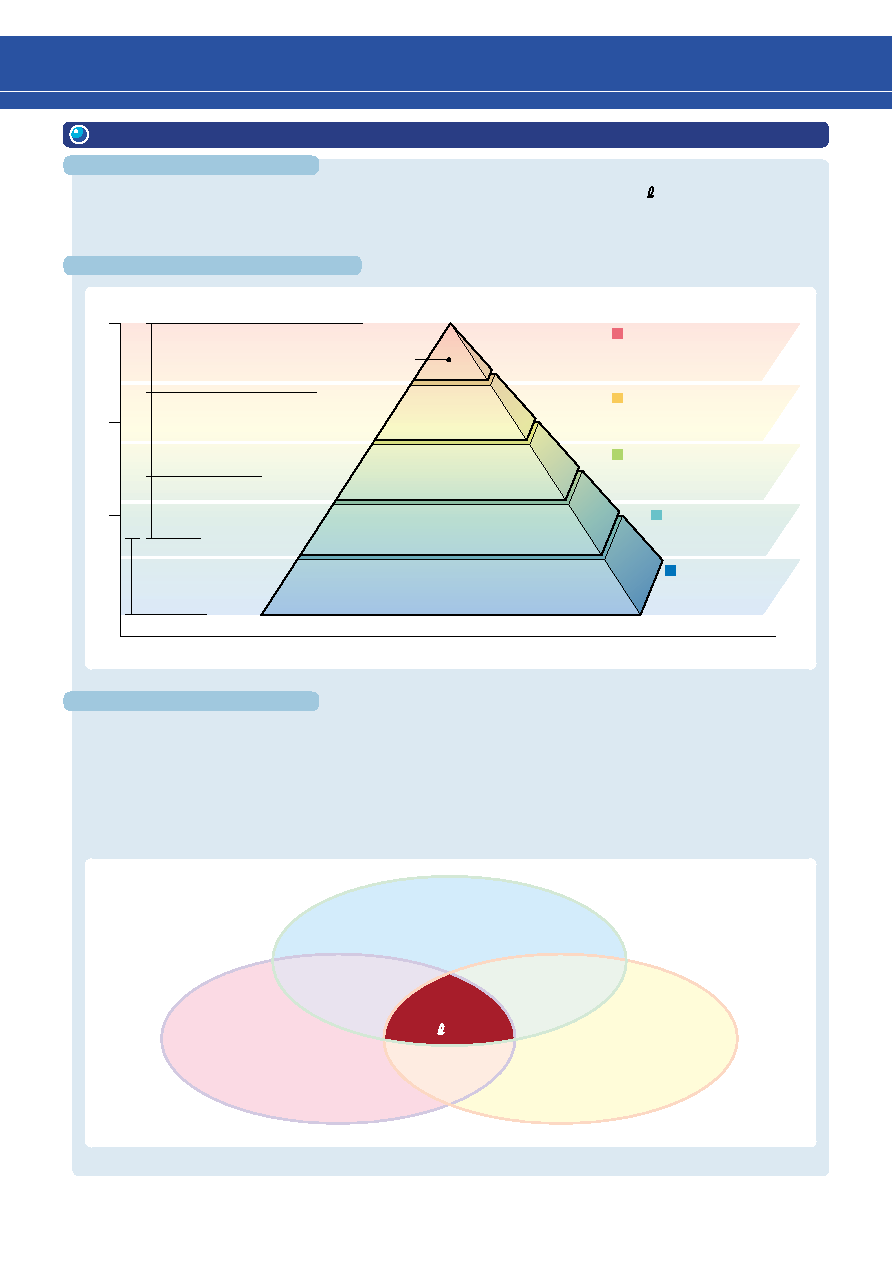
3. Merits of Four-Element High-Brightness LED Lamps
1. Higher visibility: Visibility is improved in the daytime or in bright environments.
Operating status is clear from a distance.
2. Low power dissipation: LED current and circuit power dissipation is reduced compared to these for
general-purpose LEDs with the same brightness.
10
1
0.1
cd
TL
H
Series
High-brightness lead-type
Surface-mount type
General-purpose LEDs
TL
E
Series
High-brightness lead-type
Surface-mount type
TL
U
Series
High-brightness lead-type
Surface-mount type
CHMSL : center high mounted stop lamp
Ultra-high-brightness is
the highest level of
luminosity available
High-brightness luminosity
High-brightness luminosity
Low-power /
General-purpose
LEDs
Low-end
Household appliances / PCs / AVs
Portable devices
Electronic bulletin boards
CHMSL /
Indicator lights
for controls
Traffic &
pedestrian
lights
Market Size
Four-element product lines
High brightness
(low power consumption)
Low price relative
to luminance
Four-
element LEDs
High reliability
(InGaA P--LEDs)
These are composite semiconductor devices made up of four elements (In, Ga, A and P). High-intensity
emissions are possible from pure green to red, using the same materials and the same crystal growth method.
Compared to other materials, these materials offer extremely high efficiency light emission in LEDs.
3. Fewer devices required: Number of LEDs needed for backlighting or for multiple LED applications is
reduced. Cost of mounting components also reduced.
4. Higher reliability: Product life is prolonged by reduced LED current.
8
(1) Lead type
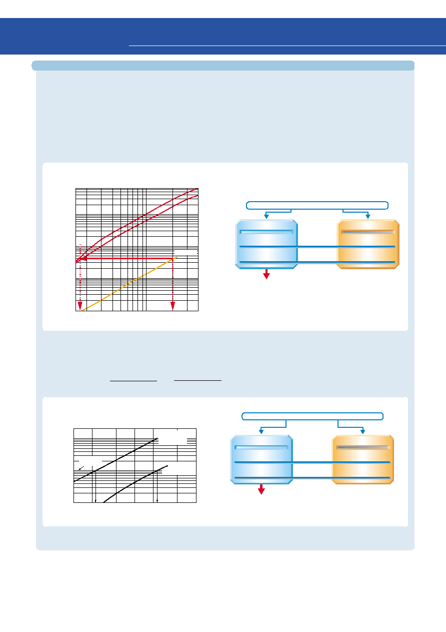
Comparison between four-element high-brightness LED lamps and general-purpose brightness LEDs
In designing sets that achieve the same luminous intensity through a four-element high-brightness LED lamp as
through a general-purpose brightness LED lamp, the use of the four-element high-brightness LED lamp reduces
the power dissipation by approximately 90%. (Toshiba internal comparison.)
TLOH160
TLOE160A
TLO163
Luminous Intensity I
V
(mcd)
Forward Current I
F
(mA)
7000
1000
100
10
2
4
6
10
20
40
50
Four-element (TLOE160A)
General-purpose (TLO163)
1.7
mA
8.5
mW
20
mA
100
mW
Drive current
Power
consumption
When the required luminance for the equipment is 40 mcd
around
91
%
Reduction in power consumption of
When a LED lamp is used at 5 V.
Four-element
General-purpose
2.4
mA
12
mW
23
mA
115
mW
When the required luminance for the equipment is 10 mcd
around
90
%
Drive current
Power
consumption
Reduction in power consumption of
When a LED lamp is used at 5 V.
q
Typical Luminous Intensity Comparison
Luminous Intensity I
V
(mcd)
Forward Current I
F
(mA)
Required
luminance
200
100
50
20
10
5
2
1
1
2
5
10
20
50
TLO1002
(general-purpose)
TLOU1002A
(four-element)
Comparison: (general-purpose LED) TLO163
(high-brightness) TLOH160, TLOE160A
q
Typical Luminous Intensity Comparison
2
Overview
q
Four-element LEDs vs. General-purpose LEDs
Example: TLOU1002A vs. TLO1002
General-purpose
Four-element
(2) SMD type
10
∞
Viewing angle
10
∞
10
∞
Viewing angle
9
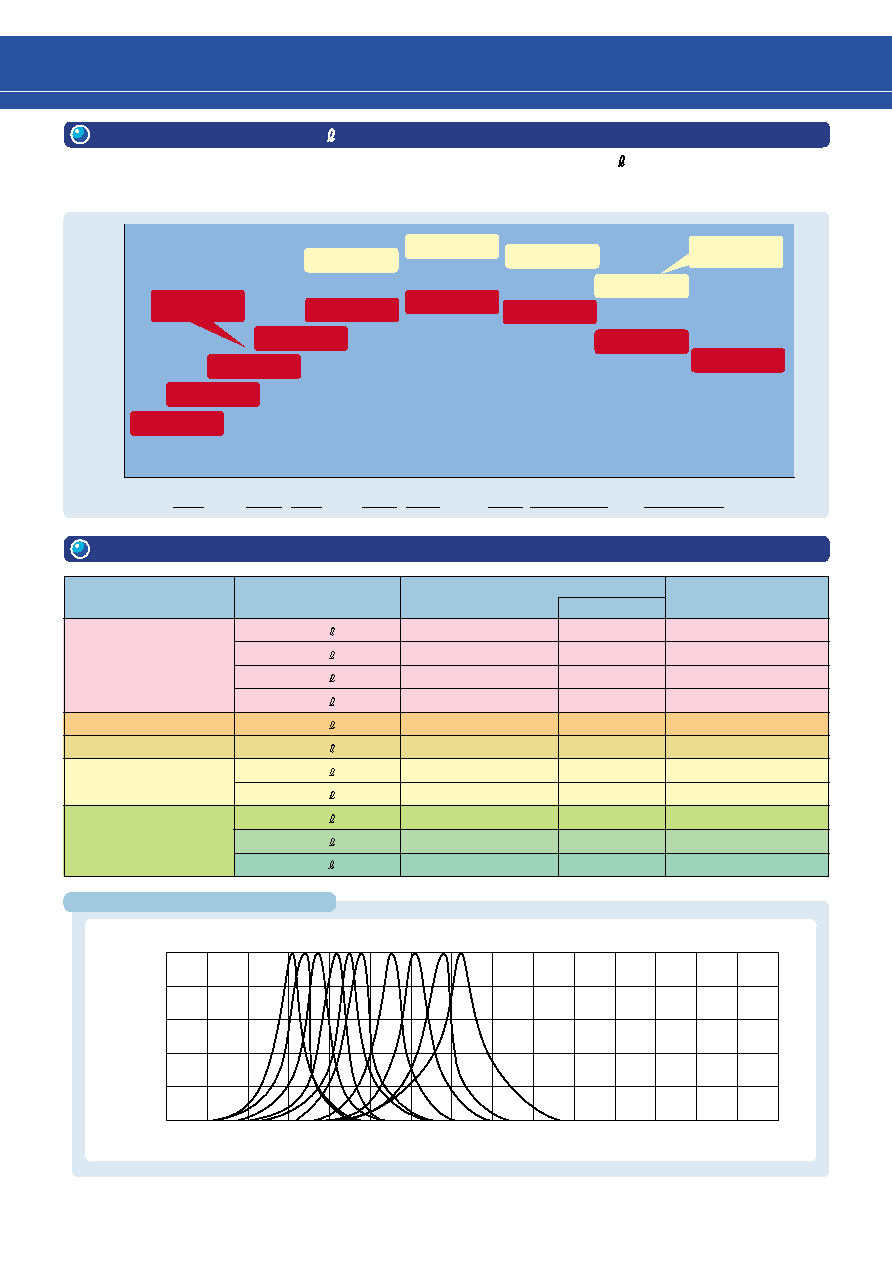
Main Products Typical Spectrum
4. About the Toshiba InGaA P LED Lamps
Toshiba are now offering a line-up consisting of several types of unpackaged InGaA P LED chip, allowing the most
appropriate device to be selected for the job at hand. An overview of the line-up is given below.
Note that the comparisons are made under the following conditions: IF = 20 mA, Ta = 25
∞
C.
Yellow
Orange
Red
d
558 nm
571 nm
587 nm
580 nm
605 nm
613 nm
565 nm
626 nm
630 nm
TLPGE
TLFGE
TLPYE
TLGE
TLYH
TLYE
TLOH
TLOE
TLSE
TLRE
TLSH
TLRME
TLRMH
New H
Series
Green
Relative luminosity
High
Low
New TL
E
Series
5. Emitted-Light Colors and Materials
Emitted-Light Color
Emitted-Light Material
Peak Emission
Wavelength (typ.)
p (nm)
Dominant
d (nm)
Color Symbol
(High-brightness series)
Red
Orange
Yellow
Green
1.0
0.8
0.6
0.4
0.2
0
500
600
700
800
Wavelength
(mm)
Relative Luminous Intensity
TLPGU
TLGU
TLFGE
TLPYE
TLAU
TLPGE
TLGE
TLYH
TLYE
TLYU
TLOH
TLOE
TLOU
TLSU
TLSH
TLSE
TLRH
TLRE
For more details, please refere to each technical data sheet.
InGaA P
644
630
RH / RE
InGaA P
636
626
RMH / RME
InGaA P
636
623
SU
InGaA P
623
613
SH / SE
InGaA P
612
605
OH / OE / OU
InGaA P
596
592
AU
InGaA P
590
587
YH / YE / YU
InGaA P
583
580
PYE
InGaA P
574
571
GE
InGaA P
568
565
FGE
562
558
PGE
Amber
InGaA P
10
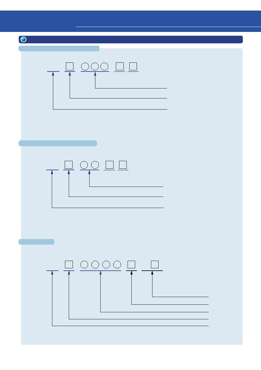
SMD Type
Lead Type
I
(Three digits type)
Lead Type
II
(Two digits type)
Example: TLYU1008A(T
04
)
This indicates that the product
belongs to the high-brightness YU
Series, has the package number
1008A and has T04 tape packing
specifications.
TL
(T )
Toshiba LED
Change code (letter)
Tape packing specifications
Color symbol (letter)
Package number (4 digits)
Product
number:
Product type is determined by color symbol and package type number.
6. Product Number Format
Product type is determined by color symbol and package type number.
Example: TLRE156AP
This indicates that the product
belongs to the high-brightness
RE Series, has the package
number 156A and is of straight
lead type.
Example: TLSU113
This indicates that the product
belongs to the SU Series, has the
package number 113 and has a
lead stopper.
TL
Product
number:
Toshiba LED
Color symbol (letter)
Package number (numbers: two digits)
Straight lead type without a lead stopper is indicated by the suffix P which is added at the end of the product number
(only applicable to products 5 mm or more in diameter).
G: Mount flush with PCB.
Resin type T: Transparent, C: Colored and transparent, D: Colored and diffusing, M: Milky-white and diffusing
Product type is determined by color symbol and package type number.
Example: TLRME68TG
This indicates that the product
belongs to the high-brightness
RME Series, has the package
number 68 and has a transpar-
ent, mount flush with PCB type
led lamp.
2
Overview
TL
Product
number:
Toshiba LED
Color symbol (letter)
Package number (numbers: three digits)
Straight lead type without a lead stopper is indicated by the suffix P
which is added at the end of the product number
(only applicable to products 5 mm or more in diameter).
Change code
G: Mount flush with PCB.

11
Luminous Intensity Classification Format (Lead type)
This example shows that the product is a
TLYH180P of ranks U and V.
Rank-classified products include two ranking
levels as standard.
Rank
Luminous Intensity (mcd)
A
0.1~0.2
B
0.18~0.36
C
0.32~0.64
D
0.56~1.12
E
1.0~2.0
F
1.8~3.6
G
3.2~6.4
H
5.6~11.2
J
10~20
K
18~36
L
32~64
Rank
Luminous Intensity (mcd)
M
56~112
N
100~200
P
180~360
Q
320~640
R
560~1,120
S
1,000~2,000
T
1,800~3,600
U
3,200~6,400
V
5,600~11,200
W
10,000~20,000
X
18,000~36,000
Y
32,000~64,000
The table to the left provides of
high-brightness LED lamp series as
common criterion for luminous
intensity classification.
Measurement tolerance for each
limit is
±
15%.
7. Lead-Type Luminous Intensity Classification Table
Example:
8. Lens Color and Appearance
Lens Type
Appearance
Transparent
Milky white, Diffusing
Colored, Transparent
Colored, Diffusing
The colored lens type is using the luminescence color.
TLYH180P (UV)
Product number
Rank symbol
12
Absolute maximum rating
Luminous intensity
Radiation (viewing) angle
Temperature dependency of luminous intensity
Ta = 25
∞
C
Pw = 10
µ
s
1 ms
10 ms
Characteristic curves (1)
20 ms
5 ms
Allowable Range
200
160
120
80
40
0
10
--
3
10
--
2
10
--
1
1
Duty Ratio D
R
Allowable Forward Pulse Current I
FP
(mA)
Ta = 25
∞
C
Pw = 10
µ
s
1 ms
10ms
Characteristic curves (2)
20ms
5 ms
120
100
80
60
40
20
0
10
--
3
10
--
2
10
--
1
1
Duty Ratio D
R
Allowable Forward Pulse Current I
FP
(mA)
120
100
80
60
40
20
0
Ta = 25
∞
C
10 ms
Characteristic curves (3)
20 ms
10
--
3
10
--
2
10
--
1
1
Duty Ratio D
R
Allowable Forward Pulse Current I
FP
(mA)
Pw = 10
µ
s
1 ms
5 ms
Allowable Range
Allowable Range
Allowable
forward pulse
current rating
(Ta = 25
∞
C)
DC Forward
I
F
max
(mA)
Allowable Forward
Pulse Current
I
FPm
ax
(Note 2)
(mA)
Note 1:
Pulse width Pw = 100
µ
s,
Duty ratio D
R
= 10
-1
Characteristic
Curves
0
∞
90
∞
90
∞
2
1
/
2
1
0.5
Relative luminosity
0
10. General LED Characteristics
Absolute maximum ratings are the rated specifications which must
not be exceeded in any operating environment. Please check the
ratings for your intended product before designing a circuit.
The light-emitting diode is assumed to be a spot light source and
the luminous intensity is defined as the flux of light per unit solid
angle for that light source.
The unit of luminous intensity is mcd.
This value is generally higher for the converging type of product
which has high directional sensitivity.
Optical output power decreases as the ambient temperature rises
at a rate of approximately 1% per
∞
C.
This parameter indicates the ratio of the LED's luminous intensity
to its axial luminous intensity (= 100%) as viewed from an angle of
with respect to the axis of the light source. The angle at which
luminous intensity is exactly 50% of the axial luminous intensity is
called the half-value angle
1/2. The half-value angle on both
sides of the axis is expressed as 2
1/2.
Viewing angle
9. Pulse Drive
Since the allowable forward pulse current varies with I
F
max, please refer to the graphs of allowable forward pulse
current ratings. Note also that pulse drive requires derating with respect to the ambient temperature, as does DC
drive.
50
200
1
25
120
2
30
3
2
Overview
13
Toshiba produces an extensive product line of newly developed ultra-high-brightness red, orange, yellow, green
and pure green LEDs using InGaA P material and optimum lens design. Toshiba high-brightness LED lamps will
help you to choose the most suitable type for your application.
1. Electrical and Optical Characteristics
Type
I
(Three digits type)
Series Name
DC forward
current
I
F
(mA)
DC reverse
voltage
V
R
(V)
Power
dissipation
P
D
(mW)
Operating
temperature
T
opr
(
∞
C)
Storage
temperature
T
stg
(
∞
C)
Forward voltage V
F
(V)
TLRE Series
50
4
120
≠40~100
≠40~120
1.9
2.4
20
50
4
644
20
630
20
TLRMH Series
50
4
120
≠40~100
≠40~120
1.9
2.4
20
50
4
636
13
626
20
TLRME Series
50
4
120
≠40~100
≠40~120
1.9
2.4
20
50
4
636
23
626
20
TLSH Series
50
4
120
≠40~100
≠40~120
2.0
2.4
20
50
4
623
13
613
20
TLSE Series
50
4
120
≠40~100
≠40~120
1.9
2.4
20
50
4
623
20
613
20
TLOH Series
50
4
120
≠40~100
≠40~120
2.0
2.4
20
50
4
612
13
605
20
TLOE Series
50
4
120
≠40~100
≠40~120
2.0
2.4
20
50
4
612
20
605
20
TLYH Series
50
4
120
≠40~100
≠40~120
2.0
2.4
20
50
4
590
13
587
20
TLYE Series
50
4
120
≠40~100
≠40~120
2.0
2.4
20
50
4
590
17
587
20
TLPYE Series
50
4
120
≠40~100
≠40~120
2.0
2.4
20
50
4
583
14
580
20
TLGE Series
50
4
120
≠40~100
≠40~120
2.0
2.4
20
50
4
574
17
571
20
TLGU Series
30
4
72
≠40~100
≠40~120
2.1
2.4
20
50
4
574
17
571
20
TLFGE Series
50
4
120
≠40~100
≠40~120
2.0
2.4
20
50
4
568
15
565
20
TLPGE Series
50
4
120
≠40~100
≠40~120
2.1
2.4
20
50
4
562
14
558
20
TLPGU Series
30
4
72
≠40~100
≠40~120
2.1
2.4
20
50
4
562
14
558
20
3
Product List for Lead Type
TLRH Series
50
4
125
≠30~85
≠40~120
1.9
2.5
20
50
4
644
18
630
20
TLRMH Series
50
4
125
≠40~100
≠40~120
2.05
2.5
20
50
4
636
20
626
20
TLRE Series
50
4
125
≠30~85
≠40~120
1.85
2.4
20
50
4
644
18
630
20
TLSH Series
50
4
125
≠30~85
≠40~120
2.1
2.5
20
50
4
623
15
613
20
TLSE Series
50
4
125
≠30~85
≠40~120
1.95
2.4
20
50
4
623
15
613
20
TLSU Series
30
4
72
Note 1
--
2.0
2.4
20
50
4
636
17
623
20
TLOH Series
50
4
125
≠30~85
≠40~120
2.1
2.5
20
50
4
612
15
605
20
TLOE Series
50
4
125
≠30~85
≠40~120
1.95
2.4
20
50
4
612
15
605
20
TLOU Series
30
4
72
Note 2
--
2.0
2.4
20
50
4
612
15
605
20
TLYH Series
50
4
125
≠30~85
≠40~120
2.1
2.5
20
50
4
590
13
587
20
TLYE Series
50
4
125
≠30~85
≠40~120
2.1
2.5
20
50
4
590
13
587
20
TLYU Series
30
4
75
Note 3
--
2.1
2.5
20
50
4
590
13
587
20
TLGE Series
50
4
140
≠30~85
≠40~120
2.27
2.8
20
50
4
574
11
571
20
TLPGE Series
50
4
140
≠30~85
≠40~120
2.27
2.8
20
50
4
562
11
558
20
Series Name
Absolute Maximum Ratings
Electrical / Optical Characterostics
DC forward
current
I
F
(mA)
DC reverse
voltage
V
R
(V)
Power
dissipation
P
D
(mW)
Operating
temperature
T
opr
(
∞
C)
Storage
temperature
T
stg
(
∞
C)
Forward voltage V
F
(V)
Reverse current I
R
(
µ
A) Standard emission wavelength characteristics (nm)
typ.
max
I
F
(mA)
max
V
R
(V)
Peak wave-
length
p
Half width
Dominant
wavelength
d I
F
(mA)
* Some individual product specifications may differ from the series specifications given above. Please check the characteristics for each device.
Reverse current I
R
(
µ
A) Standard emission wavelength characteristics (nm)
typ.
max
I
F
(mA)
max
V
R
(V)
Peak wave-
length
p
Half width
Dominant
wavelength
d
I
F
(mA)
Absolute Maximum Ratings
Electrical / Optical Characterostics
Type
II
(Two digits type)
* Some individual product specifications may differ from the series specifications given above. Please check the characteristics for each device.
Note 1: For operating and storage temperatures, please see page 14, 15.
Note 2: For operating and storage temperatures, please see page 18, 19.
Note 3: For operating and storage temperatures, please see page 20, 21.
15
14
3
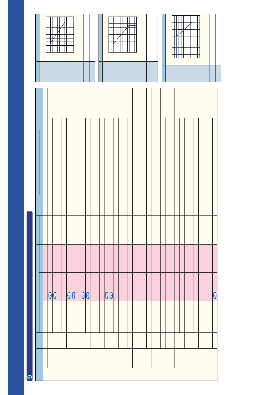
Product List for Lead Type
2. High-Brightness Red LED Lamps
x
: Mount flush with PCB
4760
4760
2720
2720
1530
2720
1530
1530
1530
850
850
850
476
850
476
476
476
272
272
2720
850
272
85
153
1530
272
153
47.6
476
476
153
153
85
85
47.6
47.6
47.6
¯5
¯5
¯3
¯10
¯3
Elliptical 5 X 5.8
4
∞
7
∞
8
∞
12
∞
15
∞
20
∞
22
∞
25
∞
30
∞
35
∞
10
∞
40
∞
80
∞
30
∞
/60
∞
6
∞
20
∞
30
∞
40
∞
9
∞
18
∞
35
∞
40
∞
60
∞
80
∞
19000
11000
9000
10000
5000
6500
4800
4200
4500
3200
2700
2240
1700
1900
1500
900
1400
800
650
4500
1800
800
220
450
4500
900
550
250
4000
1600
450
300
270
180
100
170
130
TLRH190P
TLSH20TP
TLRMH20TP
TLSH180P
TLRH180P
TLSH38TP
TLRMH38TP
TLRMH151P
TLSH17TP
TLRMH17TP
TLSH157P
TLRMH157P
TLRH157P
TLSH16TP
TLRMH16TP
TLRMH156P
TLSH156P
TLRH156P
TLRMH265P
TLSH160
TLRH160
TLSH125
TLRH262
TLRH247
TLSU180P
TLSU156P
TLSU113P
TLSU114P
TLSU163
TLSU160
TLSU164
TLSU125
TLSU123
TLSU126
TLSU124
TLSU262
TLSU268G
x
TLRH190P(WX)
--
--
TLSH180P(VW)
TLRH180P(UV)
--
--
--
--
--
TLSH157P(ST)
--
TLRH157P(ST)
--
--
--
TLSH156P(RS)
TLRH156P(QR)
--
--
TLRH160(ST)
--
TLRH262(NP)
TLRH247(PQ)
TLSU180P(TU)
TLSU156P(QR)
--
TLSU114P(NP)
--
--
--
TLSU125(PQ)
TLSU123(PQ)
--
TLSU124(MN)
TLSU262(NP)
--
200
200
200
200
200
200
200
200
200
200
200
200
200
200
200
200
200
200
200
200
200
200
200
200
120
120
120
120
120
120
120
120
120
120
120
120
120
Typical Applicons
Traffic light
Pilot lamps
(narrow range)
Pilot lamps (narrow range)
Package
Dimension
Number
Absolute Maximum Ratings
Guaranteed
Temperature
Lens Type
Typical Emitting Wavelength
Product Number
Open rank
Rank specified
Typ.
Min
Viewing
Angle
2
1/2
Package
Size
(mm)
Series
Name
Intensity
I
V
(mcd)
@I
F
=
20
mA
d (nm)
p (nm)
Message board
Backlighting
Message board
Backlighting
Message board
Pilot lamps
Pilot lamps
Message board (wide range)
Backlighting (wide range)
@Ta = 25
∞
C
DC Forward Current IF (mA) Pulse Forward Current
I
FP
(mA)
Parameter
Operating Temperature
Storage Temperature
1
I
F,
I
FP
Allowable Input Forward Current (relative value)
Ambient Temperature Ta (
∞
C)
1.2
1
0.8
0.6
0.4
0.2
0
0
20
40
60
80
100
Parameter
Operating Temperature
Storage Temperature
Derating of
Absolute Maximum
Forward Current
2
I
F,
I
FP
Allowable Input Forward Current (relative value)
Ambient Temperature Ta (
∞
C)
1.2
1
0.8
0.6
0.4
0.2
0
0
20
40
60
80
100
Parameter
Operating Temperature
Storage Temperature
3
I
F,
I
FP
Allowable Input Forward Current (relative value)
Ambient Temperature Ta (
∞
C)
1.2
1
0.8
0.6
0.4
0.2
0
0
20
40
60
80
100
120
630
613
626
613
630
613
626
626
613
626
613
626
630
613
626
626
613
630
626
613
630
613
630
630
623
623
623
623
623
623
623
623
623
623
623
623
623
644
623
636
623
644
623
636
636
623
636
623
636
644
623
636
636
623
644
636
623
644
623
644
644
636
636
636
636
636
636
636
636
636
636
636
636
636
Transparent
Transparent
Transparent
Transparent
Transparent
Transparent
Transparent
Transparent
Transparent
Transparent
Transparent
Transparent
Transparent
Transparent
Transparent
Transparent
Transparent
Transparent
Transparent
Transparent
Transparent
Transparent
Transparent
Transparent
Transparent
Red, transparent
Red, diffusing
Transparent
Transparent
Red, transparent
Red, diffusing
Transparent
Transparent
1
3
3
1
1
3
3
3
3
3
1
3
1
3
3
3
1
1
3
1
1
1
1
1
1
1
2
2
1
1
1
1
2
1
2
1
1
50
50
50
50
50
50
50
50
50
50
50
50
50
50
50
50
50
50
50
50
50
50
50
50
30
30
30
30
30
30
30
30
30
30
30
30
30
¯10-1
¯5-1
¯5-1
¯5-1
¯5-1
¯5-4
¯5-4
¯5-4
¯5-2
¯5-2
¯5-2
¯5-2
¯5-2
¯5-3
¯5-3
¯5-3
¯5-3
¯5-3
¯5-3
¯3-3
¯3-3
¯3-4
¯3-2
Elliptical-1
¯5-1
¯5-3
¯5-5
¯5-5
¯3-3
¯3-3
¯3-3
¯3-4
¯3-4
¯3-4
¯3-4
¯3-2
¯3-5
TL
H
Series
TL
U
Series
Derating of
Absolute Maximum
Forward Current
Derating of
Absolute
Maximum
Forward
Current
≠30
∞
C~85
∞
C
≠40
∞
C~120
∞
C
≠20
∞
C~75
∞
C
≠30
∞
C~100
∞
C
≠40
∞
C~100
∞
C
≠40
∞
C~120
∞
C
Pale red,
transparent
Milky-white,
diffusing
Pale red,
diffusing
Milky-white,
diffusing

17
16
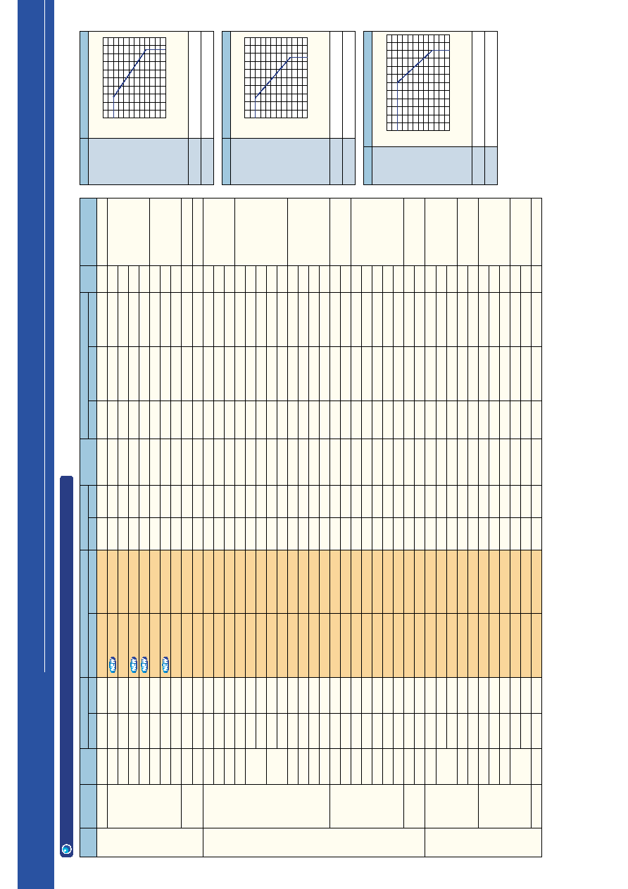
3
Product List for Lead Type
2. High-Brightness Red LED Lamps
x
: Mount flush with PCB
2720
2720
2720
1530
850
850
850
476
85
476
272
476
476
272
272
153
153
272
153
47.6
27.2
8.5
8.5
476
1530
850
850
272
272
153
85
85
47.6
47.6
47.6
15.3
8.5
272
153
85
85
7
∞
8
∞
20
∞
22
∞
25
∞
30
∞
75
∞
90
∞
130
∞
150
∞
10
∞
16
∞
45
∞
80
∞
120
∞
140
∞
30
∞
/50
∞
30
∞
/60
∞
9000
8000
7000
8000
3000
3000
2400
1500
270
1900
1000
1500
1000
1200
800
600
500
900
450
150
80
20
15
1200
3500
2200
1800
800
600
400
330
200
180
150
120
45
25
750
400
300
350
TLSE20TP
TLRME20TP
TLRE20TP
TLSE180P
TLRE180AP
TLSE17TP
TLRME17TP
TLRE17TP
TLRE138P
TLSE157P
TLRE157AP
TLSE16TP
TLSE16CP
TLRME16TP
TLRE16TP
TLRE16CP
TLRME17DP
TLSE156P
TLRE156AP
TLRE25TP
TLRE263AP
TLRE11TP
TLRE261AP
TLRE160A
TLSE50T
TLRME50T
TLRE50T
TLSE53T
TLRME53T
TLRE53T
TLRME68TG
x
TLSE62T
TLRME62T
TLRE262A
TLRE62T
TLRE60T
TLRE260A
TLSE27C
TLRME27C
TLRE27C
TLRE248
--
--
--
--
TLRE180AP(TU)
--
--
--
--
TLSE157P(ST)
TLRE157AP(RS)
--
--
--
--
--
--
TLSE156P(RS)
TLRE156AP(PQ)
--
TLRE263AP(MN)
--
--
TLRE160A(RS)
--
--
--
--
--
--
--
--
--
TLRE262A(MN)
--
--
--
--
--
--
--
200
200
200
200
200
200
200
200
200
200
200
200
200
200
200
200
200
200
200
200
200
200
200
200
200
200
200
200
200
200
200
200
200
200
200
200
200
200
200
200
200
1.2
1
0.8
0.6
0.4
0.2
0
0
20
40
60
80
100
1.2
1
0.8
0.6
0.4
0.2
0
0
20
40
60
80
100
1.2
1
0.8
0.6
0.4
0.2
0
0
20
40
60
80
100
120
613
626
630
613
630
613
626
630
630
613
630
613
613
626
630
630
626
613
630
613
630
613
630
630
613
626
630
613
626
630
626
613
626
630
630
630
630
613
626
630
630
623
636
644
623
644
623
636
644
644
623
644
623
623
636
644
644
636
623
644
644
644
644
644
644
623
636
644
623
636
644
636
623
636
644
644
644
644
623
636
644
644
Transparent
Transparent
Transparent
Transparent
Transparent
Transparent
Transparent
Transparent
Red, diffusing
Transparent
Transparent
Transparent
Red, transparent
Transparent
Transparent
Red, transparent
Red, diffusing
Transparent
Transparent
Transparent
Transparent
Transparent
Transparent
Transparent
Transparent
Transparent
Transparent
Transparent
Transparent
Transparent
Transparent
Transparent
Transparent
Transparent
Transparent
Transparent
Transparent
Red, transparent
Red, transparent
Red, transparent
Red, transparent
3
3
3
1
1
3
3
3
1
1
1
3
3
3
3
3
3
1
1
3
1
3
1
1
3
3
3
3
3
3
3
3
3
1
3
3
1
3
3
3
1
50
50
50
50
50
50
50
50
50
50
50
50
50
50
50
50
50
50
50
50
50
50
50
50
50
50
50
50
50
50
50
50
50
50
50
50
50
50
50
50
50
¯5-1
¯5-1
¯5-1
¯5-1
¯5-1
¯5-2
¯5-2
¯5-2
¯5-2
¯5-2
¯5-2
¯5-3
¯5-3
¯5-3
¯5-3
¯5-3
¯5-2
¯5-3
¯5-3
¯5-6
¯5-6
¯5-7
¯5-7
¯3-3
¯3-3
¯3-3
¯3-3
¯3-4
¯3-4
¯3-4
¯3-5
¯3-2
¯3-2
¯3-2
¯3-2
¯3-1
¯3-1
Elliptical-1
Elliptical-1
Elliptical-1
Elliptical-1
Pilot lamps
(narrow range)
Message board
Backlighting
Message board
Pilot lamps
Backlighting (wide range)
Backlighting (wide range)
¯5
¯3
Elliptical 5 X 5.8
Lens Type
Typical Emitting Wavelength
Product Number
Open rank
Rank specified
Typ.
Min
Viewing
Angle
2
1/2
Package
Size
(mm)
Series
Name
Intensity
I
V
(mcd)
@I
F
=
20
mA
d (nm)
p (nm)
Typical Applicons
Package
Dimension
Number
Absolute Maximum Ratings
Guaranteed
Temperature
DC Forward Current IF (mA) Pulse Forward Current
I
FP
(mA)
@Ta = 25
∞
C
Parameter
1
I
F,
I
FP
Allowable Input Forward Current (relative value)
Ambient Temperature Ta (
∞
C)
Derating of
Absolute Maximum
Forward Current
Operating Temperature
Storage Temperature
≠30
∞
C~85
∞
C
≠40
∞
C~120
∞
C
Parameter
Operating Temperature
Storage Temperature
≠20
∞
C~75
∞
C
≠30
∞
C~100
∞
C
Derating of
Absolute Maximum
Forward Current
2
I
F,
I
FP
Allowable Input Forward Current (relative value)
Ambient Temperature Ta (
∞
C)
Parameter
Operating Temperature
Storage Temperature
≠40
∞
C~100
∞
C
≠40
∞
C~120
∞
C
3
I
F,
I
FP
Allowable Input Forward Current (relative value)
Ambient Temperature Ta (
∞
C)
Derating of
Absolute
Maximum
Forward
Current
TL
E
Series
19
18
3
Product List for Lead Type
3. High-Brightness Orange LED Lamps
1.2
1
0.8
0.6
0.4
0.2
0
0
20
40
60
80
100
1.2
1
0.8
0.6
0.4
0.2
0
0
20
40
60
80
100
1.2
1
0.8
0.6
0.4
0.2
0
0
20
40
60
80
100
120
8500
4760
2720
2720
1530
850
850
476
850
153
4760
1530
1530
476
850
476
272
272
153
47.6
27.2
15.3
476
1530
272
153
85
27.2
15.3
272
153
2720
476
476
272
47.6
476
85
47.6
47.6
47.6
85
¯5
¯5
¯5
¯3
¯10
¯3
¯3
Elliptical 5 X 5.8
Elliptical 5 X 5.8
4
∞
7
∞
8
∞
12
∞
20
∞
22
∞
25
∞
30
∞
10
∞
80
∞
7
∞
8
∞
20
∞
22
∞
25
∞
30
∞
75
∞
90
∞
130
∞
150
∞
10
∞
16
∞
45
∞
80
∞
80
∞
120
∞
140
∞
30
∞
/50
∞
30
∞
/60
∞
6
∞
20
∞
30
∞
40
∞
9
∞
35
∞
40
∞
60
∞
30
∞
/45
∞
33000
15000
10000
7500
5000
2800
2300
1500
2300
450
10000
7000
4500
2800
2000
1600
1000
900
350
260
65
50
1500
4500
1000
350
300
100
70
800
370
7000
900
800
900
250
2500
400
180
300
200
450
TLOH190P
TLOH20TP
TLOH180P
TLOH38TP
TLOH17TP
TLOH157P
TLOH16TP
TLOH156P
TLOH160
TLOH262
TLOE20TP
TLOE180AP
TLOE17TP
TLOE157AP
TLOE16TP
TLOE16CP
TLOE156AP
TLOE266
TLOE25TP
TLOE263AP
TLOE11TP
TLOE261AP
TLOE160A
TLOE50T
TLOE53T
TLOE62T
TLOE262A
TLOE60T
TLOE260A
TLOE27C
TLOE248
TLOU180P
TLOU156P
TLOU172P
TLOU113P
TLOU114P
TLOU160
TLOU123
TLOU124
TLOU262
TLOU267
TLOU248
TLOH190P(XY)
--
TLOH180P(VW)
--
--
TLOH157P(TU)
--
TLOH156P(ST)
TLOH160(TU)
TLOH262(PQ)
--
TLOE180AP(UV)
--
TLOE157AP(ST)
--
--
TLOE156AP(RS)
TLOE266(RS)
--
TLOE263AP(PQ)
--
TLOE261AP(LM)
TLOE160A(ST)
--
--
--
TLOE262A(PQ)
--
TLOE260A(LM)
--
--
TLOU180P(UV)
TLOU156P(RS)
--
TLOU113P(RS)
TLOU114P(NP)
--
--
--
TLOU262(PQ)
--
--
605
605
605
605
605
605
605
605
605
605
605
605
605
605
605
605
605
605
605
605
605
605
605
605
605
605
605
605
605
605
605
605
605
605
605
605
605
605
605
605
605
605
612
612
612
612
612
612
612
612
612
612
612
612
612
612
612
612
612
612
612
612
612
612
612
612
612
612
612
612
612
612
612
612
612
612
612
612
612
612
612
612
612
612
Transparent
Transparent
Transparent
Transparent
Transparent
Transparent
Transparent
Transparent
Transparent
Transparent
Transparent
Transparent
Transparent
Transparent
Transparent
Transparent
Transparent
Transparent
Transparent
Transparent
Transparent
Transparent
Transparent
Transparent
Transparent
Transparent
Transparent
Transparent
Transparent
Transparent
Transparent
1
3
1
3
3
1
3
1
1
1
3
1
3
1
3
3
1
1
3
1
3
1
1
3
3
3
1
3
1
3
1
1
1
1
2
2
1
2
2
1
1
1
200
200
200
200
200
200
200
200
200
200
200
200
200
200
200
200
200
200
200
200
200
200
200
200
200
200
200
200
200
200
200
120
120
120
120
120
120
120
120
120
120
120
50
50
50
50
50
50
50
50
50
50
50
50
50
50
50
50
50
50
50
50
50
50
50
50
50
50
50
50
50
50
50
30
30
30
30
30
30
30
30
30
30
30
¯10-1
¯5-1
¯5-1
¯5-4
¯5-2
¯5-2
¯5-3
¯5-3
¯3-3
¯3-2
¯5-1
¯5-1
¯5-2
¯5-2
¯5-3
¯5-3
¯5-3
¯5-8
¯5-6
¯5-6
¯5-7
¯5-7
¯3-3
¯3-3
¯3-4
¯3-2
¯3-2
¯3-1
¯3-1
Elliptical-1
Elliptical-1
¯5-1
¯5-3
¯5-3
¯5-5
¯5-5
¯3-3
¯3-4
¯3-4
¯3-2
¯3-2
Elliptical-1
Traffic light
Pilot lamps
(narrow range)
Pilot lamps
(narrow range)
Pilot lamps
(narrow range)
Message board
Backlighting
Message board
Backlighting
Message board
Backlighting
Message board
Message board
Pilot lamps
Pilot lamps
Pilot lamps
Backlighting (wide range)
Backlighting (wide range)
Backlighting (wide range)
Backlighting (wide range)
Lens Type
Typical Emitting Wavelength
Product Number
Open rank
Rank specified
Typ.
Min
Viewing
Angle
2
1/2
Package
Size
(mm)
Series
Name
Intensity
I
V
(mcd)
@I
F
=
20
mA
d (nm)
p (nm)
Package
Dimension
Number
Absolute Maximum Ratings
Guaranteed
Temperature
DC Forward Current IF (mA) Pulse Forward Current
I
FP
(mA)
x
: Mount flush with PCB
TL
E
Series
Typical Applicons
@Ta = 25
∞
C
Parameter
1
I
F,
I
FP
Allowable Input Forward Current (relative value)
Ambient Temperature Ta (
∞
C)
Derating of
Absolute Maximum
Forward Current
Operating Temperature
Storage Temperature
Parameter
Operating Temperature
Storage Temperature
Derating of
Absolute Maximum
Forward Current
2
I
F,
I
FP
Allowable Input Forward Current (relative value)
Ambient Temperature Ta (
∞
C)
Parameter
Operating Temperature
Storage Temperature
3
I
F,
I
FP
Allowable Input Forward Current (relative value)
Ambient Temperature Ta (
∞
C)
Derating of
Absolute
Maximum
Forward
Current
≠30
∞
C~85
∞
C
≠40
∞
C~120
∞
C
≠20
∞
C~75
∞
C
≠30
∞
C~100
∞
C
≠40
∞
C~100
∞
C
≠40
∞
C~120
∞
C
TL
H
Series
TL
U
Series
Orange,
transparent
Orange,
transparent
Orange,
transparent
Orange,
transparent
Orange,
transparent
Orange,
transparent
Orange,
transparent
Orange,
transparent
Orange,
transparent
Orange,
diffusing
Orange,
diffusing
21
20
3
Product List for Lead Type
4. High-Brightness Yellow LED Lamps
8500
4760
2720
2720
2200
1530
850
850
476
850
85
153
2720
2720
1530
476
850
476
476
476
272
272
85
47.6
15.3
8.5
476
1530
850
272
153
85
85
85
47.6
27.2
15.3
272
850
153
153
153
47.6
85
47.6
47.6
47.6
476
¯5
¯5
¯5
¯3
¯10
¯3
¯3
Elliptical 5 X 5.8
Elliptical 5 X 5.8
4
∞
7
∞
8
∞
12
∞
15
∞
20
∞
22
∞
25
∞
30
∞
10
∞
80
∞
60
∞
/30
∞
5
∞
7
∞
8
∞
18
∞
20
∞
22
∞
25
∞
30
∞
75
∞
90
∞
130
∞
150
∞
10
∞
16
∞
45
∞
80
∞
120
∞
140
∞
30
∞
/50
∞
6
∞
20
∞
30
∞
40
∞
35
∞
40
∞
60
∞
90
∞
30000
13000
8000
7000
4500
4800
2500
2200
1400
4300
280
700
8000
9500
4700
2000
3000
2200
1500
1200
750
700
300
170
45
27
2300
3500
2500
800
450
340
250
240
150
85
40
650
4300
500
400
500
130
220
110
150
90
1500
TLYH190P
TLYH20TP
TLYH180P
TLYH38TP
TLYH151P
TLYH17TP
TLYH157P
TLYH16TP
TLYH156P
TLYH160
TLYH262
TLYH247
TLPYE23TP
TLYE20TP
TLYE180AP
TLPYE19TP
TLYE17TP
TLYE157AP
TLYE16TP
TLYE16CP
TLPYE18TP
TLYE156AP
TLYE25TP
TLYE263AP
TLYE11TP
TLYE261AP
TLYE160A
TLYE50T
TLPYE50T
TLYE53T
TLPYE53T
TLYE68TG
x
TLYE62T
TLYE262A
TLPYE62T
TLYE60T
TLYE260A
TLYE27C
TLYU180P
TLYU156P
TLYU172P
TLYU113P
TLYU114P
TLYU123
TLYU124
TLYU262
TLYU267
TLYU160
TLYH190P(XY)
--
TLYH180P(VW)
--
--
--
TLYH157P(TU)
--
TLYH156P(RS)
TLYH160(TU)
TLYH262(PQ)
TLYH247(QR)
--
--
TLYE180AP(UV)
--
--
TLYE157AP(ST)
--
--
--
TLYE156AP(QR)
--
TLYE263AP(NP)
--
TLYE261AP(JK)
TLYE160A(ST)
--
--
--
--
--
--
TLYE262A(NP)
--
--
TLYE260A(KL)
--
TLYU180P(TU)
TLYU156P(QR)
--
--
TLYU114P(MN)
TLYU123(NP)
TLYU124(MN)
TLYU262(MN)
--
TLYU160(ST)
587
587
587
587
587
587
587
587
587
587
587
587
580
587
587
580
587
587
587
587
580
587
587
587
587
587
587
587
580
587
580
587
587
587
580
587
587
587
587
587
587
587
587
587
587
587
587
587
590
590
590
590
590
590
590
590
590
590
590
590
583
590
590
583
590
590
590
590
583
590
590
590
590
590
590
590
583
590
583
590
590
590
583
590
590
590
590
590
590
590
590
590
590
590
590
590
Transparent
Transparent
Transparent
Transparent
Transparent
Transparent
Transparent
Transparent
Transparent
Transparent
Transparent
Transparent
Transparent
Transparent
Transparent
Transparent
Transparent
Transparent
Transparent
Transparent
Transparent
Transparent
Transparent
Transparent
Transparent
Transparent
Transparent
Transparent
Transparent
Transparent
Transparent
Transparent
Transparent
Transparent
Transparent
Transparent
Transparent
Transparent
Yellow, diffusing
Yellow, diffusing
Transparent
Transparent
1
3
1
3
1
3
1
3
1
1
1
1
3
3
1
3
3
1
3
3
3
1
3
1
3
1
1
3
3
3
3
3
3
1
3
3
1
3
1
1
1
2
2
2
2
1
1
1
50
50
50
50
50
50
50
50
50
50
50
50
50
50
50
50
50
50
50
50
50
50
50
50
50
50
50
50
50
50
50
50
50
50
50
50
50
50
30
30
30
30
30
30
30
30
30
30
200
200
200
200
200
200
200
200
200
200
200
200
200
200
200
200
200
200
200
200
200
200
200
200
200
200
200
200
200
200
200
200
200
200
200
200
200
200
120
120
120
120
120
120
120
120
120
120
¯10-1
¯5-1
¯5-1
¯5-4
¯5-4
¯5-2
¯5-2
¯5-3
¯5-3
¯3-3
¯3-2
Elliptical-1
¯5-9
¯5-1
¯5-1
¯5-10
¯5-2
¯5-2
¯5-3
¯5-3
¯5-12
¯5-3
¯5-6
¯5-6
¯5-7
¯5-7
¯3-3
¯3-3
¯3-3
¯3-4
¯3-4
¯3-5
¯3-2
¯3-2
¯3-2
¯3-1
¯3-1
Elliptical-1
¯5-1
¯5-3
¯5-3
¯5-5
¯5-5
¯3-4
¯3-4
¯3-2
¯3-2
¯3-3
Traffic light
Pilot lamps
(narrow range)
Pilot lamps
(narrow range)
Pilot lamps
(narrow range)
Message board
Backlighting
Message board
Backlighting
Message board
Backlighting
Message board
Message board
Pilot lamps
Pilot lamps
Pilot lamps
Backlighting (wide range)
Backlighting (wide range)
Backlighting (wide range)
Backlighting (wide range)
1.2
1
0.8
0.6
0.4
0.2
0
0
20
40
60
80
100
1.2
1
0.8
0.6
0.4
0.2
0
0
20
40
60
80
100
1.2
1
0.8
0.6
0.4
0.2
0
0
20
40
60
80
100
120
x
: Mount flush with PCB
Lens Type
Typical Emitting Wavelength
Product Number
Open rank
Rank specified
Typ.
Min
Viewing
Angle
2
1/2
Package
Size
(mm)
Series
Name
Intensity
I
V
(mcd)
@I
F
=
20
mA
d (nm)
p (nm)
Typical Applicons
Package
Dimension
Number
Absolute Maximum Ratings
Guaranteed
Temperature
DC Forward Current IF (mA) Pulse Forward Current
I
FP
(mA)
@Ta = 25
∞
C
Parameter
1
I
F,
I
FP
Allowable Input Forward Current (relative value)
Ambient Temperature Ta (
∞
C)
Derating of
Absolute Maximum
Forward Current
Operating Temperature
Storage Temperature
≠30
∞
C~85
∞
C
≠40
∞
C~120
∞
C
Parameter
Operating Temperature
Storage Temperature
≠20
∞
C~75
∞
C
≠30
∞
C~100
∞
C
Derating of
Absolute Maximum
Forward Current
2
I
F,
I
FP
Allowable Input Forward Current (relative value)
Ambient Temperature Ta (
∞
C)
Parameter
Operating Temperature
Storage Temperature
≠40
∞
C~100
∞
C
≠40
∞
C~120
∞
C
3
I
F,
I
FP
Allowable Input Forward Current (relative value)
Ambient Temperature Ta (
∞
C)
Derating of
Absolute
Maximum
Forward
Current
TL
H
Series
TL
E
Series
TL
U
Series
Yellow,
transparent
Yellow,
transparent
Yellow,
transparent
Yellow,
transparent
Yellow,
transparent
Yellow,
transparent
23
22
3
Product List for Lead Type
5. High-Brightness Green LED Lamps
1.2
1
0.8
0.6
0.4
0.2
0
0
20
40
60
80
100
1.2
1
0.8
0.6
0.4
0.2
0
0
20
40
60
80
100
1.2
1
0.8
0.6
0.4
0.2
0
0
20
40
60
80
100
120
2720
850
1530
1530
476
476
272
153
476
476
153
272
85
85
272
153
85
27.2
8.5
2.72
850
272
476
272
153
153
153
47.6
153
85
47.6
47.6
15.3
47.6
47.6
27.2
15.3
15.3
8.5
85
153
153
27.2
¯5
¯3
Elliptical 5 X 5.8
5
∞
7
∞
18
∞
20
∞
28
∞
30
∞
75
∞
130
∞
9
∞
16
∞
35
∞
45
∞
65
∞
80
∞
120
∞
30
∞
/50
∞
60
∞
/30
∞
7000
3000
5000
5000
2000
1300
800
500
1700
1400
430
800
150
300
700
500
200
90
20
8
2400
450
1500
1000
600
500
450
150
400
200
130
220
45
155
110
70
45
50
45
250
400
360
90
TLGE23TP
TLPGE23TP
TLFGE23TP
TLGE183P
TLPGE183P
TLGE19TP
TLFGE19TP
TLPGE19TP
TLGE159P
TLGE174P
TLPGE159P
TLGE158P
TLPGE158P
TLFGE18TP
TLGE18TP
TLGE18CP
TLPGE18TP
TLGE25TP
TLGE11TP
TLPGE11TP
TLGE160
TLPGE160
TLGE50T
TLFGE50T
TLPGE50T
TLGE125
TLGE123
TLPGE125
TLGE53T
TLFGE53T
TLPGE53T
TLGE262
TLPGE262
TLGE68TG
x
TLGE62T
TLFGE62T
TLPGE62T
TLGE60T
TLGE260
TLGE27C
TLGE247
TLGE248
TLPGE247
--
--
--
--
TLPGE183P(ST)
--
--
--
TLGE159P(ST)
--
--
TLGE158P(QR)
--
--
--
--
--
--
--
--
TLGE160(TU)
--
--
--
--
TLGE125(QR)
TLGE123(PQ)
--
--
--
--
TLGE262(NP)
--
--
--
--
--
--
TLGE260(KL)
--
TLGE247(PQ)
--
TLPGE247(LM)
571
558
565
571
558
571
565
558
571
571
558
571
558
565
571
571
558
571
571
558
571
558
571
565
558
571
571
558
571
565
558
571
558
571
571
565
558
571
571
571
571
571
558
574
562
568
574
562
574
568
562
574
574
562
574
562
568
574
574
562
574
574
562
574
562
574
568
562
574
574
562
574
568
562
574
562
574
574
568
562
574
574
574
574
574
562
Transparent
Transparent
Transparent
Transparent
Transparent
Transparent
Transparent
Transparent
Transparent
Transparent
Transparent
Transparent
Transparent
Transparent
Transparent
Transparent
Transparent
Transparent
Transparent
Transparent
Transparent
Transparent
Transparent
Transparent
Transparent
Transparent
Transparent
Transparent
Transparent
Transparent
Transparent
Transparent
Transparent
Transparent
Transparent
Transparent
Transparent
Transparent
3
3
3
1
1
3
3
3
1
1
1
1
1
3
3
3
3
3
3
3
1
1
3
3
3
1
1
1
3
3
3
1
1
3
3
3
3
3
1
3
1
1
1
50
50
50
50
50
50
50
50
50
50
50
50
50
50
50
50
50
50
50
50
50
50
50
50
50
50
50
50
50
50
50
50
50
50
50
50
50
50
50
50
50
50
50
200
200
200
200
200
200
200
200
200
200
200
200
200
200
200
200
200
200
200
200
200
200
200
200
200
200
200
200
200
200
200
200
200
200
200
200
200
200
200
200
200
200
200
¯5-9
¯5-9
¯5-9
¯5-9
¯5-9
¯5-10
¯5-10
¯5-10
¯5-10
¯5-11
¯5-10
¯5-12
¯5-12
¯5-12
¯5-12
¯5-12
¯5-12
¯5-6
¯5-7
¯5-7
¯3-3
¯3-3
¯3-3
¯3-3
¯3-3
¯3-4
¯3-4
¯3-4
¯3-4
¯3-4
¯3-4
¯3-2
¯3-2
¯3-5
¯3-2
¯3-2
¯3-2
¯3-1
¯3-1
Elliptical-1
Elliptical-1
Elliptical-1
Elliptical-1
Pilot lamps
(narrow range)
Message board
Backlighting
Message board
Pilot lamps
Backlighting (wide range)
Lens Type
Typical Emitting Wavelength
Product Number
Open rank
Rank specified
Typ.
Min
Viewing
Angle
2
1/2
Package
Size
(mm)
Series
Name
Intensity
I
V
(mcd)
@I
F
=
20
mA
d (nm)
p (nm)
Typical Applicons
Package
Dimension
Number
Absolute Maximum Ratings
Guaranteed
Temperature
DC Forward Current IF (mA) Pulse Forward Current
I
FP
(mA)
@Ta = 25
∞
C
Parameter
1
I
F,
I
FP
Allowable Input Forward Current (relative value)
Ambient Temperature Ta (
∞
C)
Derating of
Absolute Maximum
Forward Current
Operating Temperature
Storage Temperature
≠30
∞
C~85
∞
C
≠40
∞
C~120
∞
C
Parameter
Operating Temperature
Storage Temperature
≠20
∞
C~75
∞
C
≠30
∞
C~100
∞
C
Derating of
Absolute Maximum
Forward Current
2
I
F,
I
FP
Allowable Input Forward Current (relative value)
Ambient Temperature Ta (
∞
C)
Parameter
Operating Temperature
Storage Temperature
≠40
∞
C~100
∞
C
≠40
∞
C~120
∞
C
3
I
F,
I
FP
Allowable Input Forward Current (relative value)
Ambient Temperature Ta (
∞
C)
Derating of
Absolute
Maximum
Forward
Current
x
: Mount flush with PCB
TL
E
Series
Green,
transparent
Green,
transparent
Green,
transparent
Green,
transparent
Green,
transparent

25
24
3
Product List for Lead Type
5. High-Brightness Green LED Lamps
1.2
1
0.8
0.6
0.4
0.2
0
0
20
40
60
80
100
1.2
1
0.8
0.6
0.4
0.2
0
0
20
40
60
80
100
1.2
1
0.8
0.6
0.4
0.2
0
0
20
40
60
80
100
120
¯5
¯3
Elliptical 5 X 5.8
Pilot lamps
(narrow range)
Pilot lamps
(narrow range)
Message board
Backlighting
Message board
Pilot lamps
5
∞
30
∞
45
∞
55
∞
10
∞
40
∞
50
∞
80
∞
30
∞
/50
∞
(1530)
(476)
(85.0)
(27.2)
(47.6)
(47.6)
(27.2)
(27.2)
(15.3)
(476)
(153)
(47.6)
(27.2)
(47.6)
(27.2)
(27.2)
(15.3)
(27.2)
(8.5)
(47.6)
4000
1600
200
90
180
120
80
70
35
1200
450
170
80
150
70
80
40
70
25
180
TLGU23TP
TLPGU23TP
TLGU18TP
TLPGU18TP
TLGU18CP
TLGU13CP
TLPGU13CP
TLGU13DP
TLPGU13DP
TLGU50T
TLPGU50T
TLGU53T
TLPGU53T
TLGU53C
TLPGU53C
TLGU53D
TLPGU53D
TLGU62T
TLPGU62T
TLGU27C
--
--
--
--
--
--
--
--
--
--
--
--
--
--
--
--
--
--
--
--
571
558
571
558
571
571
558
571
558
571
558
571
558
571
558
571
558
571
558
571
574
562
574
562
574
574
562
574
562
574
562
574
562
574
562
574
562
574
562
574
Transparent
Transparent
Transparent
Transparent
Green,
transparent
Green, diffusing
Green, diffusing
Transparent
Transparent
Transparent
Transparent
Green, diffusing
Green, diffusing
Transparent
Transparent
3
3
3
3
3
3
3
3
3
3
3
3
3
3
3
3
3
3
3
3
30
30
30
30
30
30
30
30
30
30
30
30
30
30
30
30
30
30
30
30
120
120
120
120
120
120
120
120
120
120
120
120
120
120
120
120
120
120
120
120
¯5-9
¯5-9
¯5-12
¯5-12
¯5-12
¯5-5
¯5-5
¯5-5
¯5-5
¯3-3
¯3-3
¯3-4
¯3-4
¯3-4
¯3-4
¯3-4
¯3-4
¯3-2
¯3-2
Elliptical-1
Typical Applicons
@Ta = 25
∞
C
Parameter
1
I
F,
I
FP
Allowable Input Forward Current (relative value)
Ambient Temperature Ta (
∞
C)
Derating of
Absolute Maximum
Forward Current
Operating Temperature
Storage Temperature
≠30
∞
C~85
∞
C
≠40
∞
C~120
∞
C
Parameter
Operating Temperature
Storage Temperature
≠20
∞
C~75
∞
C
≠30
∞
C~100
∞
C
Derating of
Absolute Maximum
Forward Current
2
I
F,
I
FP
Allowable Input Forward Current (relative value)
Ambient Temperature Ta (
∞
C)
Parameter
Operating Temperature
Storage Temperature
≠40
∞
C~100
∞
C
≠40
∞
C~120
∞
C
3
I
F,
I
FP
Allowable Input Forward Current (relative value)
Ambient Temperature Ta (
∞
C)
Derating of
Absolute
Maximum
Forward
Current
Lens Type
Typical Emitting Wavelength
Product Number
Open rank
Rank specified
Typ.
Min
Viewing
Angle
2
1/2
Package
Size
(mm)
Series
Name
Intensity
I
V
(mcd)
@I
F
=
20
mA
d (nm)
p (nm)
Package
Dimension
Number
Absolute Maximum Ratings
Guaranteed
Temperature
DC Forward Current IF (mA) Pulse Forward Current
I
FP
(mA)
x
: Mount flush with PCB
TL
U
Series
Green,
transparent
Green,
transparent
Green,
transparent
Green,
transparent
Green,
transparent
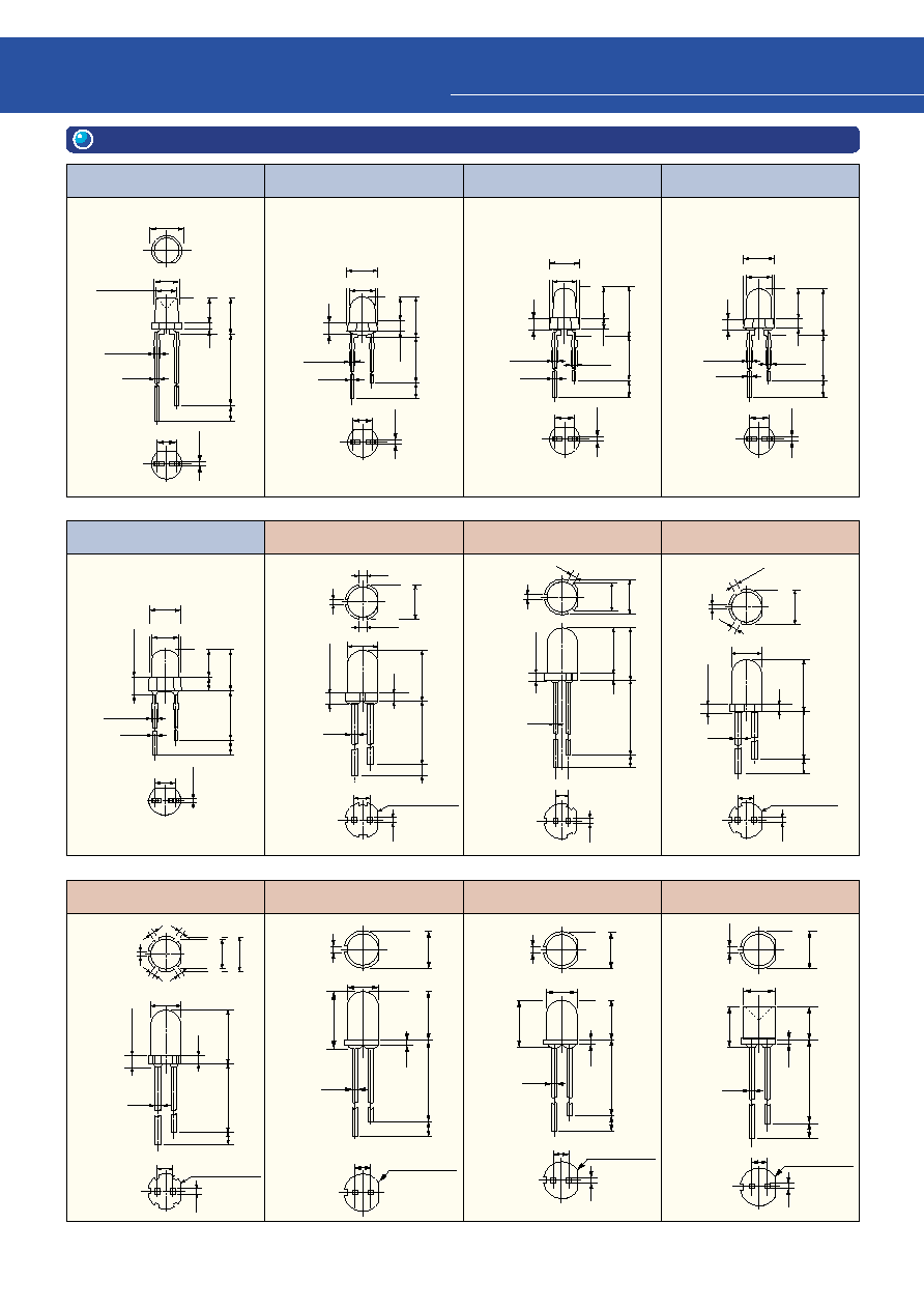
26
3
Product List for Lead Type
6. Package Dimensions
¯3-5
¯5-3
¯5-4
¯5-5
¯5-6
¯5-7
¯3-1
¯3-2
¯3-3
¯3-4
¯5-2
¯5-1
2
1
2.54
1. Anode
2. Cathode
1. Anode
2. Cathode
1. Anode
2. Cathode
1. Anode
2. Cathode
1. Anode
2. Cathode
1. Anode
2. Cathode
1. Anode
2. Cathode
1. Anode
2. Cathode
1. Anode
2. Cathode
1. Anode
2. Cathode
1. Anode
2. Cathode
1. Anode
2. Cathode
¯3
±
0.2
¯2.8
±
0.2
0.45
0.7 max
24
±
1
(2)
(1)
4.8
±
0.2
3.2
±
0.2
¯3.8
±
0.2
2
1
2.54
0.45
0.45
¯3.1
±
0.2
¯3.8
±
0.2
24
±
1
(2)
5.1
±
0.2
0.7 max
1.6 max
(include resinoid
protuberance)
(1.3)
3.5
±
0.2
2
1
2.54
2.1 max
(include resinoid
protuberance)
24
±
1
(2)
(1.3)
5.84
±
0.2
3.74
±
0.2
0.7 max
0.7 max
¯3.1
±
0.2
¯3.8
±
0.2
2
1
2.54
24
±
1
(2)
(1.3)
5.6
±
0.2
3.5
±
0.2
0.7 max
0.7 max
¯3.1
±
0.2
¯3.8
±
0.2
0.45
¯3.8
±
0.2
¯3.1
±
0.2
5.2
±
0.2
24
±
1
3.2
±
0.2
(2)
(2)
0.6 max
0.45
2.54
1
2
¯5.8
±
0.2
(1)
¯5
±
0.2
20
±
1
(2)
9.65
±
0.2
2.54
1
2
(1.5)
(1.5)
(1)
Cathode index
0.5
¯5.8
8.3
±
0.2
(1)
1.5 max
20.0
±
1
(2)
9.3
±
0.25
¯5.0
2.54
0.5
1
2
(1)
(1)
¯5.8
±
0.2
(1)
1.5 max
¯5
±
0.2
20
±
1
(2)
8.75
±
0.2
2.54
1
2
(1.5)
(1.5)
(1)
Cathode index
0.5
¯5.8
±
0.2
¯5.0
±
0.2
(1)
2.5 max
¯5
±
0.2
20
±
1
(2)
9.42
±
0.26
2.54
1
2
(1)
(1)
(1)
(1)
(1)
Cathode index
0.5
¯5.0
±
0.2
21
±
1
7.65
±
0.2
(1)
¯5.8
±
0.2
(1)
(2)
2.54
Cathode index
Cathode index
0.5
1
2
2.54
2
1
0.5
¯5.0
±
0.2
21
±
1
5.65
±
0.2
(2)
(1)
¯5.8
±
0.2
(1)
2.54
2
1
0.5
¯4.9
±
0.2
21
±
1
6
±
0.2
(2)
(1)
(1)
¯5.8
±
0.2
Cathode index
0.45
0.5
2.1 max
(include resinoid
protuberance)
1.5 max
(include resinoid
protuberance)
2.7 max
(include resinoid
protuberance)
8.65
±
0.25
(include resinoid
protuberance)
6.65
±
0.25
(include resinoid
protuberance)
7
±
0.25
(include resinoid
protuberance)
0.45
0.45
0.45
0.45
0.5
0.5
0.5
0.5
0.5

27
¯5-10
(Unit:mm)
¯5-11
¯5-12
¯10-1
Elliptical-1
¯5-8
¯5-9
1. Anode
2. Cathode
1. Anode
2. Cathode
1. Anode
2. Cathode
1. Anode
2. Cathode
1. Anode
2. Cathode
1. Anode
2. Cathode
1. Anode
2. Cathode
2.54
1
2
7.75
±
0.2
2.5 max
11.25
+0.4
17.5
±
1
(2)
(1)
≠
0.1
¯
5.8
¯
5.0
120
∞
(1)
(1.5)
(1.5)
¯5.0
±
0.2
20
±
1
9.8
±
0.2
(1)
¯
5.8
±
0.2
(1)
2.54
0.5
R0.4
Cathode index
(2)
2
1
¯5.0
±
0.2
20
±
1
9.55
±
0.2
8.55
±
0.2
(1)
(2)
¯
5.8
±
0.2
(1)
(1)
2.54
0.5
Cathode index
2
1
20
±
1
9.3
±
0.2
(1)
(2)
¯
5.8
±
0.2
(1)
(1)
2.54
0.5
Cathode index
1.5 max
2
1
¯5.0
±
0.2
20
±
1
9.0
±
0.2
(1)
(2)
¯
5.8
±
0.2
(1)
1.5
1.5
2.54
0.5
2
1
Cathode index
2
1
¯10
21
±
1
14.1
±
0.2
(1)
¯
10.4
(2)
2.54
0.5
5.0
±
0.2
5.8
±
0.2
5.8
±
0.2
17.5
±
1
8.25
±
0.2
(2)
+0.4
10.75
≠
0.1
2.54
1
2
0.5
9.5 max
¯
5.0
0.5
0.5
0.5
1.5 max
(include resinoid
protuberance)
1.5 max
(include resinoid
protuberance)
1.5 max
(include resinoid
protuberance)
2.5 max
(include resinoid
protuberance)
(1)
Cathode index
0.5
0.5
0.5
0.5
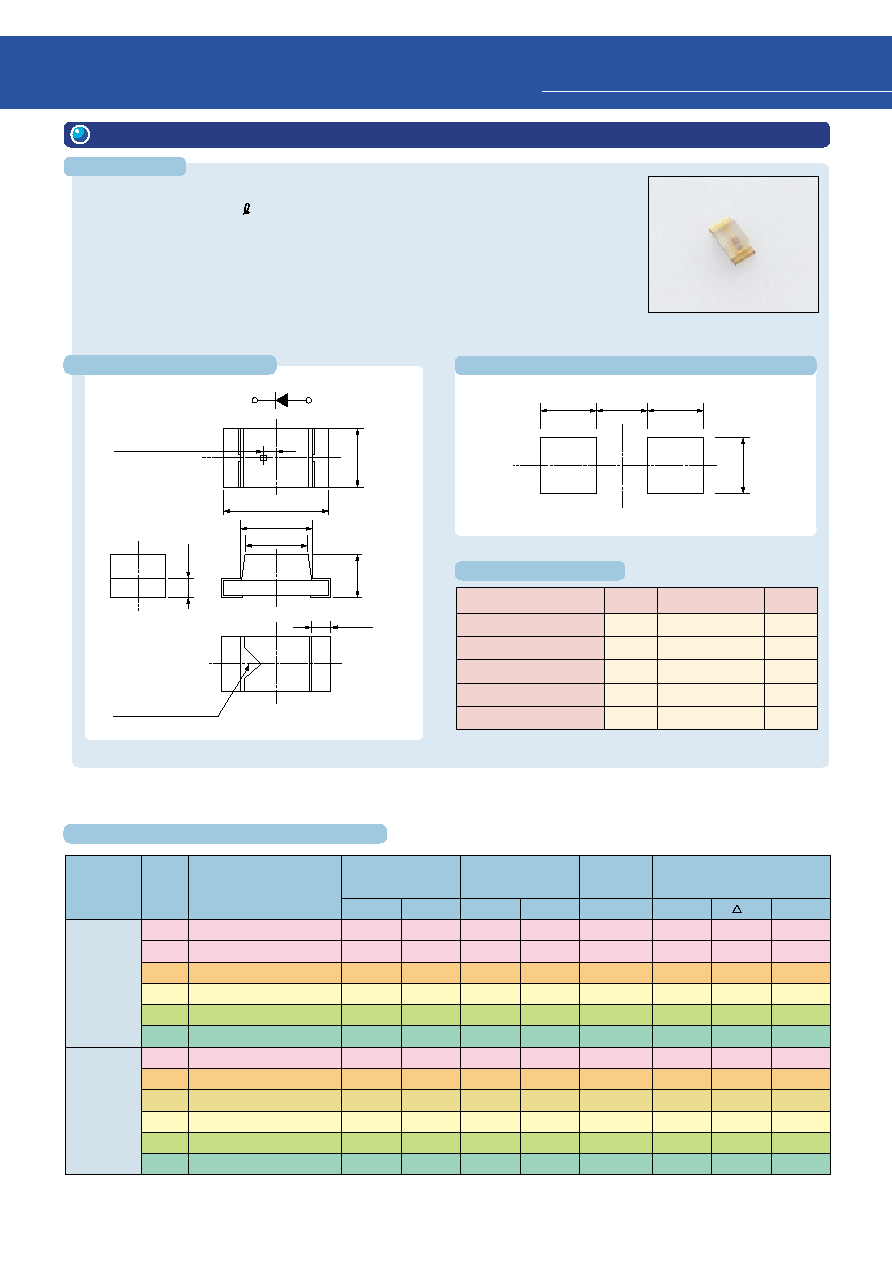
28
Features
1. TL
1008A (T04), TL
1008A (T5)
Characteristics
Rating
DC Forward Current
DC Reverse Voltage
Power Dissipation
Operating Temperature
Storage Temperature
25
4
60~62.5
(Note 1)
≠40~85
≠40~100
Symbol
Unit
I
F
V
R
P
D
Topr
Tstg
mA
V
mW
∞
C
∞
C
Note 1: please refer to each technical datasheet.
(unit: mm)
1
2
Polarity
LED chip is located
(0.2)
Cathode index
0.8
0.2
1.6
1.1
(1.0)
0.6
0.3
1
2
Tolerance:
±
0.1
1. Cathode
2. Anode
0.8
0.7
0.8
(0.8)
(unit: mm)
q
Package dimensions: 1.6 (L) x 0.8 (W) x 0.6 (H) mm
q
Four-element (InGaA P)
q
High-brightness and low power consumption can be accomplished by a switch-
over from general-purpose lamps.
q
Taping with 4 mm (T04 specification) and 2 mm (T05 specification) pitch is
standard. Achieves mounting efficiency.
q
Product height of 0.6 mm is suitable for use as backlighting for thin equipment.
Series
Name
TL
E Series
TLRE1008A(T04)/(T05)
TLSE1008A(T04)/(T05)
TLOE1008A(T04)/(T05)
TLYE1008A(T04)/(T05)
TLGE1008A(T04)/(T05)
TLPGE1008A(T04)/(T05)
TLSU1008A(T04)/(T05)
TLOU1008A(T04)/(T05)
TLAU1008A(T04)/(T05)
TLYU1008A(T04)/(T05)
TLGU1008A(T04)/(T05)
TLPGU1008A(T04)/(T05)
Emitted-
Light
Color
Red
Red
Orange
Yellow
Green
Pure green
Red
Orange
Amber
Yellow
Green
Pure green
Product Number
Min
Typ.
Typ.
Max
Max
p
d
27.2
47.6
47.6
27.2
27.2
4.76
27.2
27.2
8.5
8.5
8.5
1.53
70
140
180
105
70
18
60
78
30
30
30
6
1.9
1.9
2.0
2.0
2.0
2.1
2.0
2.1
2.1
2.1
2.1
2.1
2.4
2.4
2.4
2.4
2.4
2.4
2.4
2.5
2.5
2.5
2.5
2.5
50
50
50
50
50
50
50
50
50
50
50
50
644
623
612
590
574
562
636
612
596
590
574
562
18
17
15
13
11
11
17
15
13
13
11
11
630
613
605
587
571
558
623
605
592
587
571
558
Typical Luminous Intensity
I
V
(mcd)
@I
F
= 20 mA
Forward Voltage V
F
(V)
@I
F
= 20 mA
Reverse Current
I
R
(
µ
A)
@V
R
= 4 V
Typical Emission Wavelength
(nm)
@I
F
= 20 mA
TL
U Series
4
Product List for SMD Type
(Ta = 25
∞
C)
Maximum Rating
Recommended Soldering Pad Dimensions
Package Dimensions
Electrical and Optical Characteristics
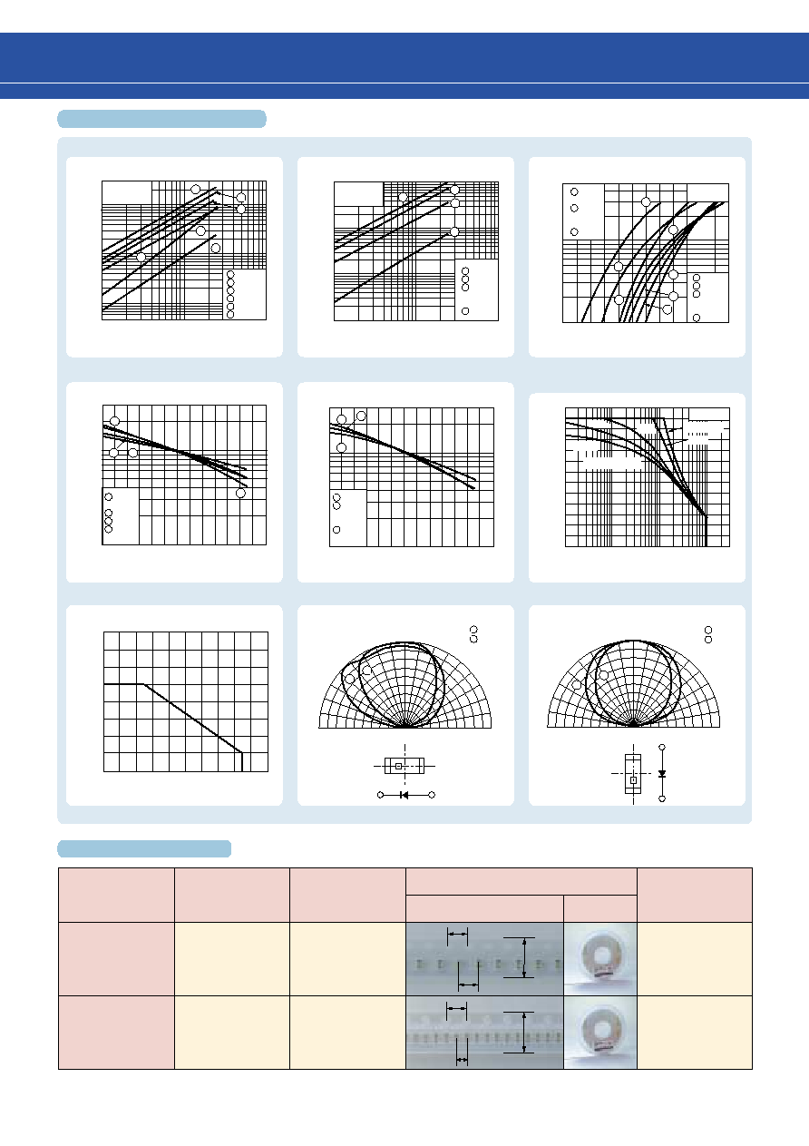
29
Tape Packing Type
Pitches
Embossed
Tape Packing
Tape Type Suffix
Packing
Package dimensions (mm)
Appearance
Quantity/Reel
T04
4 mm
Embossed
Tape Packing
T05
2 mm
4000/reel
8000/reel
4
4
4
8
8
2
Horizontal direction
90
∞
80
∞
70
∞
60
∞
50
∞
40
∞
30
∞
20
∞
10
∞
0
10
∞
20
∞
30
∞
40
∞
50
∞
60
∞
70
∞
80
∞
0
0.2 0.4 0.6 0.8
1
2
Ta = 25
∞
C
TL
E
TL
U
90
∞
80
∞
70
∞
60
∞
50
∞
40
∞
30
∞
20
∞
10
∞
0
10
∞
20
∞
30
∞
40
∞
50
∞
60
∞
70
∞
80
∞
90
∞
0
0.2 0.4 0.6 0.8 1.0
1
2
Vertical direction
1
2
1
2
TL
E
TL
U
Luminous Intensity I
V
(mcd)
300
100
50
30
10
5
3
1
0.5
Luminous Intensity I
V
(mcd)
100
50
30
10
5
3
1
0.5
0.3
0.1
Ta = 25
∞
C
Ta = 25
∞
C
Ta = 25
∞
C
3
2
4
1
5
6
TLRE
TLSE
TLOE
TLYE
TLGE
TLPGE
TLSU
TLOU
TLAU
TLYU
TLGU
TLPGU
TLRE
TLSE
TLOE
TLYE
TLGE
TLPGE
TLRE
TLSE
TLOE
TLYE
TLGE
TLPGE
TLSU
TLOU
TLAU
TLYU
TLGU
TLPGU
1
3
5
10
30
50
100
1
3
5
10
30
50
100
Forward Current I
F
(mA)
I
V --
I
F
I
V --
I
F
I
F --
V
F
I
V --
T
C
Allowable forward pulse current
characteristics
I
V --
T
C
I
F --
T
a
Forward Current I
F
(mA)
2
Case Temperature T
C
(
∞
C)
Case Temperature T
C
(
∞
C)
Forward Voltage V
F
(V)
Forward Current I
F
(mA)
Relative Luminous Intensity I
V
Relative Luminous Intensity I
V
Allowable Forward Current I
F
(mA)
Ambient Temperature Ta (
∞
C)
40
30
20
10
0
0
20
40
60
80
100
3
1
0.5
0.3
0.1
50
30
10
5
3
1
3
1
0.5
0.3
0.1
≠20
1.6
1.7
1.8
1.9
2.0
2.1
2.2
0
20
40
60
80
100
≠20
0
20
40
60
80
100
3
2
4
1
3
2
1
1
2
3
4
5
6
7
TLSU
TLOU
TLAU
TLYU
TLGU
TLPGU
1
2
3
4
1
3
4
1
2
3
4
5
6
4
5
6
7
1
2
3
1
2
3
4
1
2
3
Allowable Forward Pulse Current
I
FP
(mA)
120
100
80
60
40
20
0
1
Ta = 25
∞
C
Radiation pattern
Duty Ratio D
R
10
≠3
10
≠2
10
≠1
10 ms
20 ms
1 ms
5 ms
Allowable Range
P
W
= 10
µ
s
Tape Specifications
Characteristics Diagram
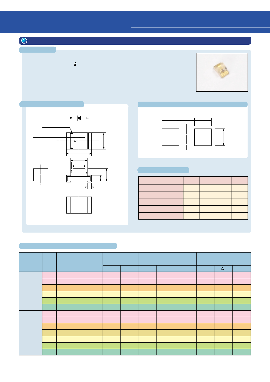
30
Characteristics
Rating
DC Forward Current
DC Reverse Voltage
Power Dissipation
Operating Temperature
Storage Temperature
25
4
60~62.5
(Note 1)
≠40~85
≠40~100
Symbol
Unit
I
F
V
R
P
D
Topr
Tstg
mA
V
mW
∞
C
∞
C
Note 1: please refer to each technical datasheet.
q
Package dimensions: 2.0 (L) x 1.25 (W) x 1.1 (H) mm
q
Four-element (InGaA P )
q
High-brightness and low power consumption can be accomplished by a
switchover from general-purpose lamps.
q
Product height of 1.1 mm is suitable for use as backlighting for thin equip-
ment.
1
2
Polarity
LED chip is located
(0.25)
Cathode index
1.25
0.5
1.4
2.0
(1.28)
1.1
0.4
±
0.2
1
2
Tolerance:
±
0.1
1. Cathode
2. Anode
1.2
1.0
1.2
(1.2)
TLRE1002A(T02)
TLSE1002A(T02)
TLOE1002A(T02)
TLYE1002A(T02)
TLGE1002A(T02)
TLPGE1002A(T02)
TLRU1002A(T02)
TLSU1002A(T02)
TLOU1002A(T02)
TLAU1002A(T02)
TLYU1002A(T02)
TLGU1002A(T02)
TLPGU1002A(T02)
Red
Red
Orange
Yellow
Green
Pure green
Red
Red
Orange
Amber
Yellow
Green
Pure green
27.2
47.6
47.6
27.2
27.2
4.76
15.3
27.2
27.2
8.5
8.5
8.5
1.53
70
140
180
105
70
18
45
60
78
30
30
30
6
1.9
1.9
2.0
2.0
2.0
2.1
2.0
2.0
2.1
2.1
2.1
2.1
2.1
2.4
2.4
2.4
2.4
2.4
2.4
2.4
2.4
2.5
2.5
2.5
2.5
2.5
50
50
50
50
50
50
50
50
50
50
50
50
50
644
623
612
590
574
562
644
636
612
596
590
574
562
18
17
15
13
11
11
18
17
15
13
13
11
11
630
613
605
587
571
558
630
623
605
592
587
571
558
Series
Name
Emitted-
Light
Color
Product Number
Min
Typ.
Typ.
Max
Max
p
d
Typical Luminous Intensity
I
V
(mcd)
@I
F
= 20 mA
Forward Voltage V
F
(V)
@I
F
= 20 mA
Reverse Current
I
R
(
µ
A)
@V
R
= 4 V
Typical Emission Wavelength
(nm)
@I
F
= 20 mA
TL
E
Series
TL
U
Series
4
Product List for SMD Type
Maximum Rating
Recommended Soldering Pad Dimensions
Package Dimensions
Features
(unit: mm)
(unit: mm)
2. TL
1002A (T02)
Electrical and Optical Characteristics
(Ta = 25
∞
C)

31
Tape Packing Type
Pitches
Embossed
Tape Packing
Tape Type Suffix
Packing
Package dimensions
(mm)
Appearance
Quantity/Reel
T02
4 mm
3000/reel
4
4
8
90
∞
80
∞
70
∞
60
∞
50
∞
40
∞
30
∞
20
∞
10
∞
0
10
∞
20
∞
30
∞
40
∞
50
∞
60
∞
70
∞
80
∞
90
∞
0
0.2 0.4 0.6 0.8 1.0
90
∞
80
∞
70
∞
60
∞
50
∞
40
∞
30
∞
20
∞
10
∞
0
10
∞
20
∞
30
∞
40
∞
50
∞
60
∞
70
∞
80
∞
90
∞
0
0.2 0.4 0.6 0.8 1.0
≠20
0
20
40
60
80
100
Allowable Forward Current I
F
(mA)
Ambient Temperature Ta (
∞
C)
I
V --
I
F
I
V --
I
F
I
F --
V
F
I
V --
T
C
Allowable forward pulse current
characteristics
I
V --
T
C
I
F --
T
a
300
100
50
30
10
5
3
1
0.5
Luminous Intensity I
V
(mcd)
100
50
30
10
5
3
1
0.5
0.3
0.1
Ta = 25
∞
C
3
2
4
1
5
6
1
3
5
10
30
50
100
1
3
5
10
30
50
100
Forward Current I
F
(mA)
3
2
4
1
Forward Voltage V
F
(V)
50
30
10
5
3
1
1.6
1.7
1.8
1.9
2.0
2.1
2.2
Case Temperature T
C
(
∞
C)
Relative Luminous Intensity I
V
3
2
4
1
3
1
0.5
0.3
0.1
Case Temperature T
C
(
∞
C)
3
1
0.5
0.3
0.1
≠20
0
20
40
60
80
100
3
2
1
Allowable Forward Pulse Current
I
FP
(mA)
Duty Ratio D
R
120
100
80
60
40
20
0
10
≠3
10
≠2
10
≠1
1
Ta = 25
∞
C
20 ms
1 ms
5 ms
P
W
= 10
µ
s
10 ms
40
30
20
10
0
0
20
40
60
80
100
1
2
1
2
Horizontal direction
Ta = 25
∞
C
TL
E
TL
U
Vertical direction
1
2
1
2
TL
E
TL
U
Radiation pattern
Allowable Range
TLSU
TLOU
TLAU
TLYU
TLGU
TLPGU
1
2
3
Relative Luminous Intensity I
V
Luminous Intensity I
V
(mcd)
Ta = 25
∞
C
TLRE
TLSE
TLOE
TLYE
TLGE
TLPGE
Forward Current I
F
(mA)
1
2
3
4
5
6
TLSU
TLOU
TLAU
TLYU
TLGU
TLPGU
1
2
3
4
Ta = 25
∞
C
TLSU
TLOU
TLAU
TLYU
TLGU
TLPGU
TLRE
TLSE
TLOE
TLYE
TLGE
TLPGE
Forward Current I
F
(mA)
1
3
4
5
6
7
4
5
6
7
2
1
2
3
TLRE
TLSE
TLOE
TLYE
TLGE
TLPGE
1
2
3
4
Tape Specifications
Characteristics Diagram
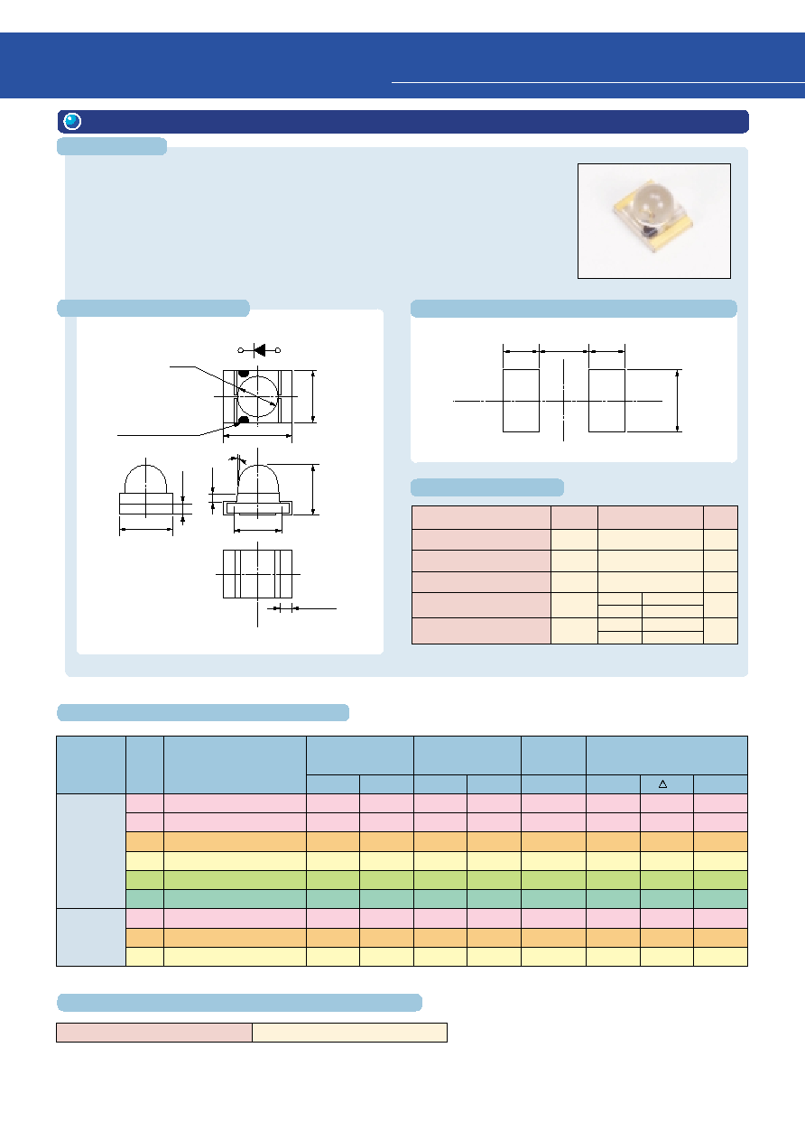
32
Characteristics
Rating
DC Forward Current
DC Reverse Voltage
Power Dissipation
Operating Temperature
Storage Temperature
25
4
60~62.5
(Note 1)
Symbol
Unit
I
F
V
R
P
D
Topr
Tstg
mA
V
mW
∞
C
∞
C
Note 1: please refer to each technical datasheet.
≠25~80
≠40~85
≠30~85
≠40~100
TL
U
TL
E
TL
U
TL
E
q
Package dimensions: 3.2 (L) x 2.4 (W) x 2.4 (H) mm
q
Unique ¯2 mm lens top structure substantially improves light extraction.
q
Designed for miniaturization and slimming while maintaining high luminance
q
Optical axis precision is substantially improved over lead-frame structure LEDs.
Designed to reduce nonuniformity in the display
1.1
2.0
1.1
(2.8)
(2.2)
(6
∞
)
Cathode index
3.2
2.4
¯2.0
1
2
2.4
0.5
±
0.2
2.4
0.5
0.5
1
2
Tolerance:
±
0.1
1. Cathode
2. Anode
Polarity
TLRE1005B(T03)
TLSE1005B(T03)
TLOE1005B(T03)
TLYE1005B(T03)
TLGE1005B(T03)
TLPGE1005B(T03)
TLSU1005A(T03)
TLOU1005A(T03)
TLYU1005A(T03)
Red
Red
Orange
Yellow
Green
Pure green
Red
Orange
Yellow
153
272
476
272
153
47.6
153
153
47.6
450
1000
1500
850
350
130
450
450
140
1.9
1.9
2.0
2.0
2.0
2.1
2.0
2.0
2.1
2.4
2.4
2.4
2.4
2.4
2.4
2.4
2.4
2.5
50
50
50
50
50
50
50
50
50
644
623
612
590
574
562
636
612
590
18
17
15
13
11
11
17
15
13
630
613
605
587
571
558
623
605
587
TL
E Series
TL
U Series
Series
Name
Emitted-
Light
Color
Product Number
Min
Typ.
Typ.
Max
Max
p
d
Typical Luminous Intensity
I
V
(mcd)
@I
F
= 20 mA
Forward Voltage V
F
(V)
@I
F
= 20 mA
Reverse Current
I
R
(
µ
A)
@V
R
= 4 V
Typical Emission Wavelength
(nm)
@I
F
= 20 mA
4
Product List for SMD Type
(unit: mm)
(unit: mm)
Maximum Rating
Recommended Soldering Pad Dimensions
Package Dimensions
Features
Electrical and Optical Characteristics
3. TL
E1005B (T03), TL
U1005A (T03)
(Ta = 25
∞
C)
Absorption Head Diameter
¯1.2 mm
Automatic Mounting: Recommended Conditions
Please ask the mounting equipment maker
for the ideal automatic mounting conditions.

33
Tape Packing Type
Pitches
Embossed
Tape Packing
Tape Type Suffix
Packing
Package dimensions
(mm)
Appearance
Quantity/Reel
T03
4 mm
1000/reel
4
4
8
90
∞
80
∞
70
∞
60
∞
50
∞
40
∞
30
∞
20
∞
10
∞
0
10
∞
20
∞
30
∞
40
∞
50
∞
60
∞
70
∞
80
∞
90
∞
0
0.2 0.4 0.6 0.8 1.0
120
100
80
60
40
20
0
1
0
20
40
60
80
100
Ta = 25
∞
C
I
V --
I
F
I
F --
V
F
I
V --
T
C
I
F --
Ta
Allowable forward pulse current
characteristics
Radiation pattern
3000
1000
500
300
100
50
30
10
TLRE
TLSE
TLOE
TLYE
TLGE
TLPGE
TLYU
TLSU
TLOU
1
3
5
10
30
50
100
Forward Current I
F
(mA)
50
30
10
5
3
1
Ta = 25
∞
C
TLRE
TLSE
TLOE
TLYE
TLGE
TLSU
TLOU
TLPGE
TLYU
1.6
1.7
1.8
1.9
2.0
2.1
2.2
Forward Voltage V
F
(V)
Case Temperature T
C
(
∞
C)
Relative Luminous Intensity I
V
TLRE
TLSE
TLSU
TLOE
TLYE
TLGE
TLPGE
TLOU
TLYU
3
1
0.5
0.3
0.1
≠20
0
20
40
60
80
100
40
30
20
10
0
Luminous Intensity I
V
(mcd)
Ta = 25
∞
C
Forward Current I
F
(mA)
Allowable Forward Pulse Current
I
FP
(mA)
Ta = 25
∞
C
Duty Ratio D
R
10
≠3
10
≠2
10
≠1
10 ms
20 ms
1 ms
5 ms
Allowable Range
P
W
= 10
µ
s
Allowable Forward Current I
F
(mA)
Ambient Temperature Ta (
∞
C)
TL
E1005B
TL
U1005A
Characteristics Diagram
Tape Specifications
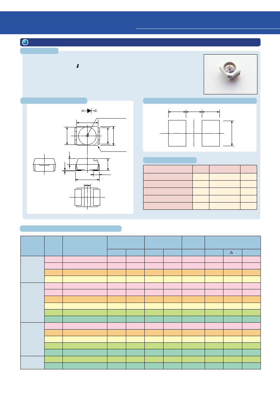
34
Characteristics
Rating
DC Forward Current
DC Reverse Voltage
Power Dissipation
Operating Temperature
Storage Temperature
30 / 50
(Note 1)
4
72~140
(Note 1)
≠40~100
≠40~100
Symbol
Unit
I
F
V
R
P
D
Topr
Tstg
mA
V
mW
∞
C
∞
C
Note 1: please refer to each technical datasheet.
q
Package dimensions: 3.2 (L) x 2.8 (W) x 1.9 (H) mm
q
Four-element (InGaA P)
q
High-heat resistance extends the operating temperature range.
Topr = ≠40~100
∞
C
3.2
(3.5)
0.8
(1.4)
2.8
2.2
1.9
0.8
(0.1)
¯
2.4
Tolerance:
±
0.2
1
2
1
2
Polarity
LED chip is located
Cathode index
1. Anode
2. Cathode
1.65
1.15
1.65
2.41
Others
TLRH1100(T09)
TLSH1100(T09)
TLOH1100(T09)
TLYH1100(T09)
TLRE1100(T11)
TLSE1100(T11)
TLOE1100(T11)
TLYE1100(T11)
TLGE1100(T11)
TLPGE1100(T11)
TLSU1100(T09)
TLOU1100(T09)
TLYU1100(T09)
TLGU1100(T09)
TLPGU1100(T09)
S4F42Q1(T09)
S4F42Z1(T09)
Red
Red
Orange
Yellow
Red
Red
Orange
Yellow
Green
Pure green
Red
Orange
Yellow
Green
Pure green
Green
Pure green
47.6
85
85
85
47.6
47.6
47.6
47.6
47.6
8.5
27.2
47.6
15.3
15.3
4.76
47.6
8.5
130
240
260
190
100
180
180
150
100
25
80
100
50
45
12
110
25
1.9
2.1
2.1
2.1
1.9
1.9
2.0
2.0
2.0
2.1
2.0
2.0
2.1
2.3
2.3
2.27
2.27
2.5
2.5
2.5
2.5
2.4
2.4
2.4
2.4
2.4
2.4
2.4
2.4
2.5
2.8
2.8
2.8
2.8
50
50
50
50
50
50
50
50
50
50
50
50
50
50
50
50
50
644
623
612
590
644
623
612
590
574
562
636
612
590
574
562
574
562
18
15
15
13
18
15
15
13
11
11
17
15
13
11
11
11
11
630
613
605
587
630
613
605
587
571
558
623
605
587
571
558
571
558
Series
Name
Emitted-
Light
Color
Product Number
Min
Typ.
Typ.
Max
Max
p
d
Typical Luminous Intensity
I
V
(mcd)
@I
F
= 20 mA
Forward Voltage V
F
(V)
@I
F
= 20 mA
Reverse Current
I
R
(
µ
A)
@V
R
= 4 V
Typical Emission Wavelength
(nm)
@I
F
= 20 mA
TL
E Series
TL
U Series
TL
H Series
4
Product List for SMD Type
4. TL
1100 (T09), TL
E1100 (T11), S4F42
(T09)
(unit: mm)
(unit: mm)
Maximum Rating
Recommended Soldering Pad Dimensions
Package Dimensions
Features
Electrical and Optical Characteristics
(Ta = 25
∞
C)
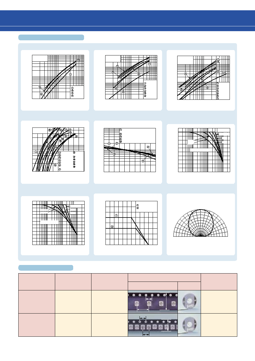
35
Tape Packing Type
Pitches
Embossed
Tape Packing
Tape Type Suffix
Packing
Package dimensions
(mm)
Appearance
Quantity/Reel
T09
8 mm
Embossed
Tape Packing
T11
4 mm
1000/reel
2000/reel
4
4
4
8
12
8
90
∞
80
∞
70
∞
60
∞
50
∞
40
∞
30
∞
20
∞
10
∞
0
10
∞
20
∞
30
∞
40
∞
50
∞
60
∞
70
∞
80
∞
90
∞
0
0.2 0.4 0.6 0.8 1.0
1.6
1.8
2.0
2.2
2.4
2.6
Ta = 25
∞
C
I
V --
I
F
I
V --
I
F
I
V --
I
F
I
V --
T
C
Allowable forward pulse current
characteristics
I
F --
V
F
Allowable forward pulse current
characteristics
I
F --
Ta
Allowable Forward Pulse Current
I
FP
(mA)
Duty Ratio D
R
10
≠3
10
≠2
10
≠1
1
1
Luminous Intensity I
V
(mcd)
1000
500
300
100
50
30
10
Ta = 25
∞
C
TLRH
TLSH
TLOH
TLYH
1
3
5
10
30
50
100
Forward Current I
F
(mA)
Luminous Intensity I
V
(mcd)
500
300
100
50
30
10
5
3
1
Ta = 25
∞
C
TLRE
TLSE
TLOE
TLYE
TLGE
TLPGE
1
3
5
10
30
50
100
Forward Current I
F
(mA)
Ta = 25
∞
C
S4F42Q1
S4F42Z1
TLSU
TLOU
TLYU
TLGU
TLPGU
Forward Current I
F
(mA)
Forward Current I
F
(mA)
300
100
50
30
10
5
3
1
1
3
5
10
30
50
100
Ta = 25
∞
C
TLRH
TLSH
TLOH,TLYH
TLRE
TLSE
TLOE,TLYE,
TLGE
TLPGE
S4F42Q1,
S4F42Z1
TLSU
TLOU
TLYU
TLGU
TLPGU
Forward Voltage V
F
(V)
Forward Current I
F
(mA)
50
30
10
5
3
1
TLRH, TLSH, TLOH, TLYH
TLRE,TLOE, TLGE, TLPGE
TLYE, TLSU
S4F42Q1, S4F42Z1,TLOU
TLYU
TLGU, TLPGU
Relative Luminous Intensity I
V
Case Temperature T
C
(
∞
C)
10
5
3
1
0.5
0.3
0.1
≠25
0
25
50
75
100
Allowable Forward Current I
F
(mA)
Ambient Temperature Ta (
∞
C)
80
60
40
20
0
0
20
40
60
100
80
120
TL
E and others
TL
U
TL
H / TL
E / S4F
series
TL
U series
120
100
80
60
40
20
0
10 ms
20 ms
1 ms
5 ms
Radiation pattern
1 ms
10 ms
20 ms
5 ms
200
160
120
80
40
0
Allowable Forward Pulse Current
I
FP
(mA)
Ta = 25
∞
C
Duty Ratio D
R
10
≠3
10
≠2
10
≠1
Allowable Range
PW = 10
µ
s
Allowable Range
Ta = 25
∞
C
P
W
= 10
µ
s
Tape Specifications
Characteristics Diagram

36
Characteristics
Rating
DC Forward Current
DC Reverse Voltage
Power Dissipation
Operating Temperature
Storage Temperature
30/50
(Note 1)
4
72~140
(Note 1)
≠40~100
≠40~100
Symbol
Unit
I
F
V
R
P
D
Topr
Tstg
mA
V
mW
∞
C
∞
C
Note1: please refer to each technical datasheet.
q
Package dimensions: 3.2 (L) x 2.8 (W) x 3.4 (H) mm
q
4-element (InGaA P), H Series / U Series
q
High-heat resistance extends the operating temperature range.
Topr = ≠40~100
∞
C
¯2.8
Tolerance:
±
0.2
1. Anode
2. Cathode
3.2
2.8
2.2
1.1
1
2
1
2
Polarity
LED chip is located
Cathode index
3.5
0.8
3.4
(0.1)
1.65
1.15
1.65
2.41
TLRH1102(T10)
TLSH1102(T10)
TLOH1102(T10)
TLYH1102(T10)
TLRE1102(T10)
TLSE1102(T10)
TLOE1102(T10)
TLYE1102(T10)
TLGE1102(T10)
TLPGE1102(T10)
TLSU1102(T10)
TLOU1102(T10)
TLYU1102(T10)
TLGU1102(T10)
TLPGU1102(T10)
S4F43Q1(T10)
S4F43Z1(T10)
85
153
272
153
85
272
272
153
85
27.2
85
85
47.6
47.6
8.5
85
27.2
320
600
650
480
320
600
650
480
300
75
200
250
130
120
30
250
60
1.9
2.1
2.1
2.1
1.9
1.9
2.0
2.0
2.0
2.1
2.0
2.0
2.1
2.3
2.3
2.27
2.27
2.5
2.5
2.5
2.5
2.4
2.4
2.4
2.4
2.4
2.4
2.4
2.4
2.5
2.8
2.8
2.8
2.8
50
50
50
50
50
50
50
50
50
50
50
50
50
50
50
50
50
644
623
612
590
644
623
612
590
574
562
636
612
590
574
562
574
562
18
15
15
13
18
17
15
13
11
11
17
15
13
11
11
11
11
630
613
605
587
630
613
605
587
571
558
623
605
587
571
558
571
558
Others
Red
Red
Orange
Yellow
Red
Red
Orange
Yellow
Green
Pure green
Red
Orange
Yellow
Green
Pure green
Green
Pure green
Series
Name
Emitted-
Light
Color
Product Number
Min
Typ.
Typ.
Max
Max
p
d
Typical Luminous Intensity
I
V
(mcd)
@I
F
= 20 mA
Forward Voltage V
F
(V)
@I
F
= 20 mA
Reverse Current
I
R
(
µ
A)
@V
R
= 4 V
Typical Emission Wavelength
(nm)
@I
F
= 20 mA
TL
E Series
TL
U Series
TL
H Series
4
Product List for SMD Type
5. TL
1102 (T10), S4F43
(T10)
Maximum Rating
Recommended Soldering Pad Dimensions
Package Dimensions
Features
Electrical and Optical Characteristics
(unit: mm)
(unit: mm)
(Ta = 25
∞
C)
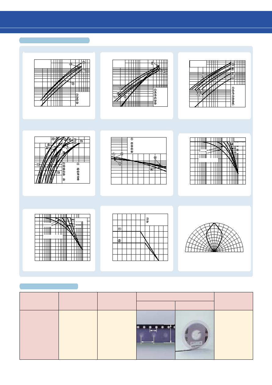
37
Tape Packing Type
Pitches
Embossed
Tape Packing
Tape Type Suffix
Packing
Package dimensions
(mm)
Appearance
Quantity/Reel
T10
8 mm
500/reel
4
8
12
90
∞
80
∞
70
∞
60
∞
50
∞
40
∞
30
∞
20
∞
10
∞
0
10
∞
20
∞
30
∞
40
∞
50
∞
60
∞
70
∞
80
∞
90
∞
0
0.2 0.4 0.6 0.8 1.0
Ta = 25
∞
C
1.6
1.8
2.0
2.2
2.4
2.6
I
V --
I
F
I
V --
I
F
I
V --
I
F
I
V --
T
C
Allowable forward pulse current
characteristics
I
F --
V
F
Allowable forward pulse current
characteristics
I
F --
Ta
Allowable Forward Pulse Current
I
FP
(mA)
Duty Ratio D
R
1
Allowable Forward Pulse Current
I
FP
(mA)
Duty Ratio D
R
1
Forward Current I
F
(mA)
Luminous Intensity I
V
(mcd)
3000
1000
500
300
100
50
30
10
Ta = 25
∞
C
TLRH
TLSH
TLOH
TLYH
1
3
5
10
30
50
100
3000
1000
500
300
100
50
30
10
5
Luminous Intensity I
V
(mcd)
Ta = 25
∞
C
TLRE
TLSE
TLOE
TLYE
TLGE
TLPGE
1
3
5
10
30
50
100
Forward Current I
F
(mA)
Ta = 25
∞
C
S4F42Q1
S4F43Z1
TLSU
TLOU
TLYU
TLGU
TLPGU
Forward Current I
F
(mA)
Luminous Intensity I
V
(mcd)
500
300
100
50
30
10
5
3
1
1
3
5
30
10
50
100
Ta = 25
∞
C
TLRH
TLSH
TLOH,TLYH
TLRE, TLSE
TLOE,TLYE,
TLGE
TLPGE
S4F43Q1,
S4F43Z1
TLSU
TLOU
TLYU
TLGU
TLPGU
50
30
10
5
3
1
10
5
3
1
0.5
0.3
0.1
≠25
0
25
50
75
100
80
60
40
20
0
0
20
40
60
100
80
120
Allowable Forward Current I
F
(mA)
Ambient Temperature Ta (
∞
C)
TL
E and others
TL
U
10
≠3
10
≠2
10
≠1
TLRH, TLSH, TLOH, TLYH
TLRE,TLOE, TLGE, TLPGE
TLYE, TLSU
S4F42Q1, S4F42Z1,TLOU
TLYU
TLGU, TLPGU
Relative Luminous Intensity I
V
Case Temperature T
C
(
∞
C)
Forward Voltage V
F
(V)
Forward Current I
F
(mA)
TL
H / TL
E / S4F
series
TL
U series
120
100
80
60
40
20
0
Radiation pattern
200
160
120
80
40
0
10
≠3
10
≠2
10
≠1
10 ms
20 ms
1 ms
5 ms
Allowable Range
Ta = 25
∞
C
P
W
= 10
µ
s
10 ms
20 ms
1 ms
5 ms
Allowable Range
Ta = 25
∞
C
P
W
= 10
µ
s
Characteristics Diagram
Tape Specifications
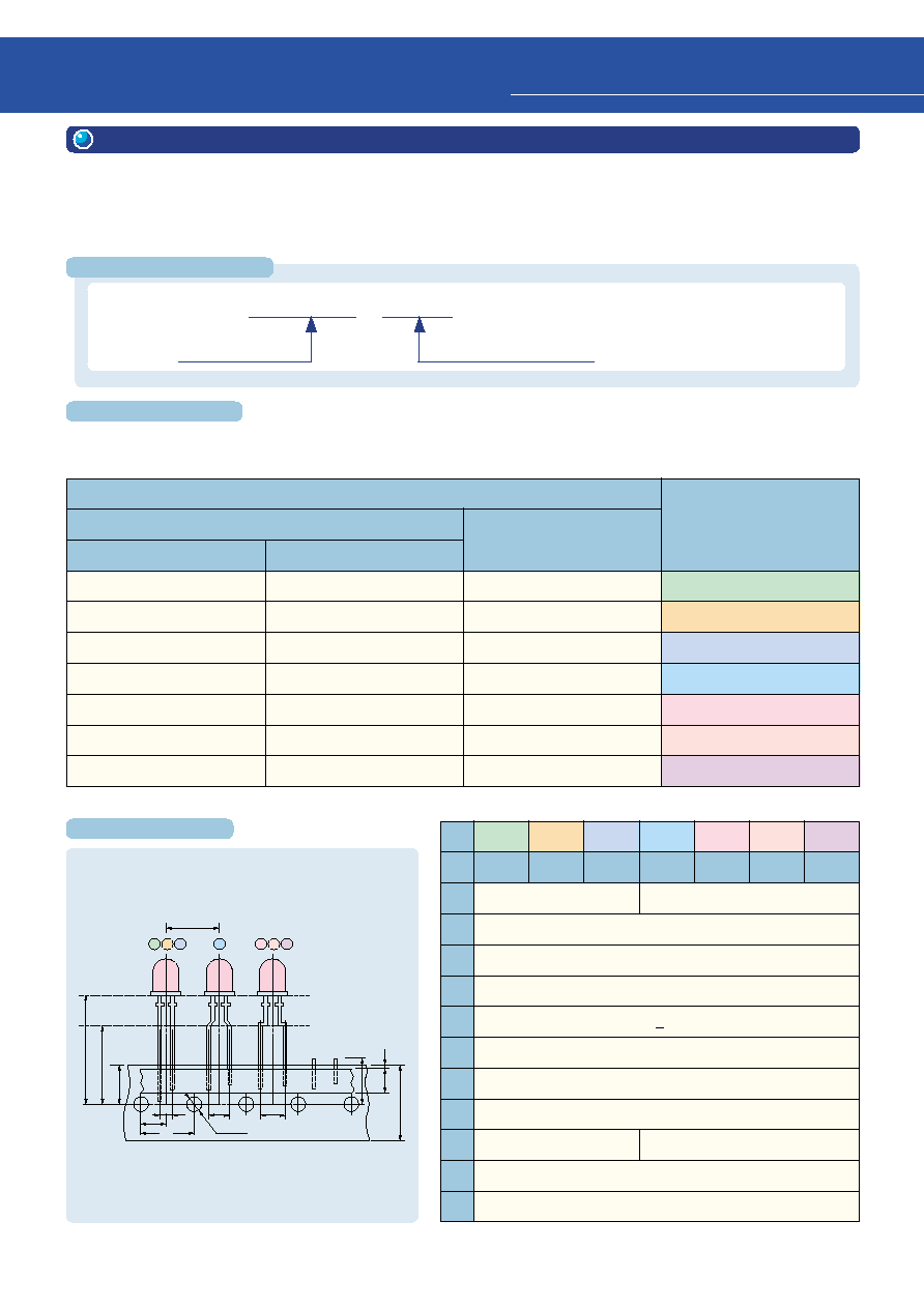
38
Example:
TLRE180AP (TPK51)
Product number
Tape specification
TPK1
TPKR1
TPK51
TPK3
TPKR3
TPK53
TPK5
TPKR5
TPK55
TPJ1
TPJR1
TPJ51
TPJ2
TPJR2
TPJ52
TPJ3
TPJR3
TPJ53
TPJ6
TPJR6
TPJ56
Tapes are classified by lead polarity, packing style and distance from the device base to the tape feedhole
centerline, as shown below.
Tape Specifications
Reel pack
Tape Forms
Anode lead-out
Cathode lead-out
Ammo pack
A
B
C
D
E
F
G
1. Lead Type
1-1 Tape packing
These tape specifications apply to 2-lead LED lamps with diameters of 3.1 mm and 5 mm.
These LED lamps have 2.54 mm and 5 mm lead pitches respectively, and can be mounted on a circuit board using
an auto-insertion machine. Packing can either be in an ammo pack or a reel pack as desired.
A
B
C
D
E
F
G
Unit: mm
H
H
0
W
W
0
W
1
W
2
P
0
P
1
P
2
F
L
D
0
23.35
±
1.0 18.55
±
1.0 17.0
±
1.0 23.35
±
1.0 20.5
±
1.0 22.5
±
1.0 23.35
±
1.0
--
16.0
±
0.5
18.0
+ 1
≠ 0.5
9.0
+ 0.75
≠ 0.5
6.0
±
0.3 or 13.0
±
0.3
0.5
12.7
12.7
±
1 (product pitch)
6.35
±
1.3
2.54
+ 0.8
≠ 0.2
11.0 max
¯4.0
±
0.2
5.00
+ 0.8
≠ 0.2
H
F
P
1
F
F
L
A
H
0
P
2
P
0
D
0
W
2
W
0
W
W
1
B C
D
E F G
Product number format
Tape specifications
Tape dimensions
5
Packing Specifications
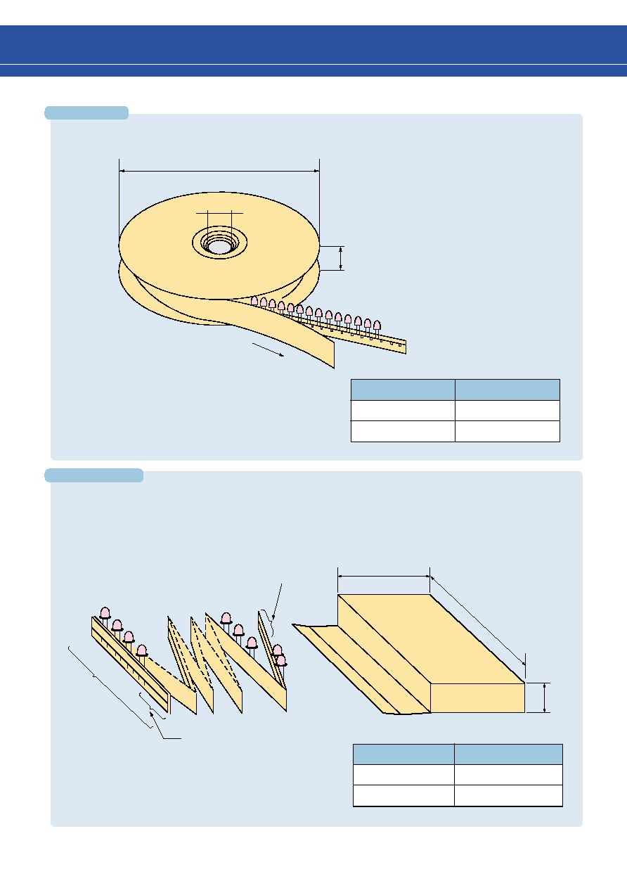
39
Reel pack
Ammo pack
(1) Taped devices are packed by alternately folding the tape every 25 devices.
(2) Four or more devices are removed from the beginning and end of the tape.
s
Reel dimensions and winding
s
Contents
LED type
Quantity per Reel
¯3 Series
2,000
¯5 Series
1,000
s
Contents
LED type
Quantity per Reel
¯3 Series
2,000 or 4,000
¯5 Series
1,000 or 2,000
¯2
¯1
Direction of tape feed
t
¯1 = 360 mm
t = 50 mm
¯2 = 30 mm
d1
¯3.1 series
d1 = 140
or 270 mm
d2 = 336 mm
d3 = 52 mm
¯5 series
d1 = 248 mm
d2 = 339 mm
d3 = 55 mm
d2
d3
Four or more devices
are removed
Four or more devices are removed
25 devices
per row
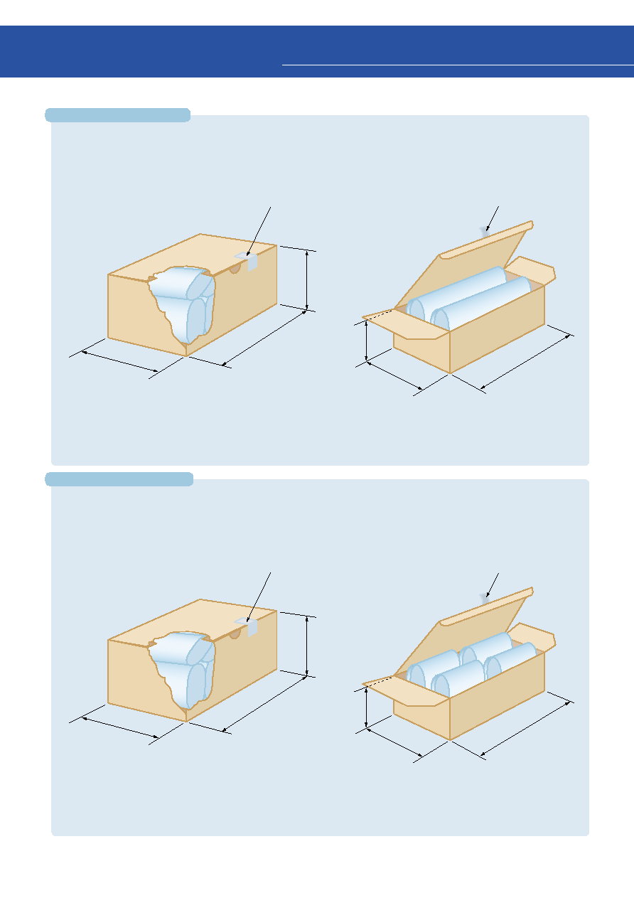
40
5
Packing Specifications
Packing for ¯5-mm type
180 mm
(external)
80 mm
(external)
260 mm
(external)
120 mm
(external)
180 mm
(external)
85 mm
(external)
Packing box
Packing box
Quality guarantee tape
Quality guarantee tape
180 mm
(external)
80 mm
(external)
260 mm
(external)
120 mm
(external)
180 mm
(external)
85 mm
(external)
Packing box
Packing box
Quality guarantee tape
Quality guarantee tape
q
Large box (standard)
q
Small box
q
Large box (standard)
q
Small box
10 bags with 5,000 LED lamps
2 bags with 1,000 LED lamps
20 bags with 10,000 LED lamps
4 bags with 2,000 LED lamps
Minimum number of LED lamps: 500 per plastic bag
Minimum number of LED lamps: 500 per plastic bag
1-2 Packing (Devices are loose in bags.)
Packing for ¯3-mm type
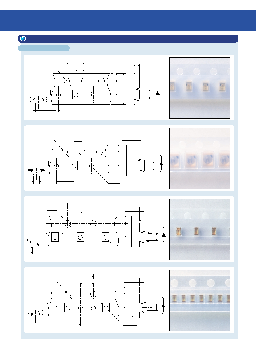
41
2.25
±
0.1
8.0
±
0.3
3.50
±
0.05
1.30
±
0.05
1.75
±
0.1
0.25
±
0.05
1.5
+0.1
≠0
1.1
±
0.1
4.0
±
0.1
2.0
±
0.05
4.0
±
0.1
1.45
±
0.1
A - A'
A
A'
Polarity
3.5
±
0.1
8.0
±
0.3
3.50
±
0.05
2.7
±
0.1
1.75
±
0.1
0.25
±
0.05
4.0
±
0.1
2.0
±
0.05
4.0
±
0.1
Polarity
1.1
±
0.1
2.8
±
0.1
1.5
+0.1
≠0
A - A'
A
A'
T02
T03
T04
T05
1.75
±
0.1
8.0
±
0.1
3.50
±
0.05
0.75
±
0.1
1.75
±
0.1
0.20
±
0.05
4.0
±
0.1
2.0
±
0.05
4.0
±
0.1
0.6
±
0.05
0.9
±
0.1
Polarity
1.5
+0.1
≠0
A - A'
A
A'
8.0
±
0.1
3.50
±
0.05
0.75
±
0.1
1.75
±
0.1
0.20
±
0.05
4.0
±
0.1
2.0
±
0.05
2.0
±
0.1
0.6
±
0.05
0.9
±
0.1
Polarity
1.5
+0.1
≠0
A - A'
A
A'
1.75
±
0.1
2. SMD Type
Tape dimensions
(Unit: mm)

42
12.0
±
0.3
5.5
±
0.05
A
1.75
±
0.1
0.3
±
0.05
1.5
+0.1
≠0
4.0
±
0.1
2.0
±
0.05
8.0
±
0.1
1.5
+0.1
≠0
2.9
±
0.1
A - A'
3.7
±
0.1
Dimensions
of part A
T09
2.3
±
0.1 3.6
±
0.1
T10
Polarity
8.0
±
0.3
3.5
±
0.05
2.3
±
0.1
1.75
±
0.1
0.3
±
0.05
4.0
±
0.1
2.0
±
0.05
4.0
±
0.1
Polarity
(1.5
±
0.1)
1.5
+0.1
≠0
3.7
±
0.1
2.9
±
0.1
A - A'
T09, T10
T11
Corresponds to
EIAJ RRM08B
¯
60
¯13
±
0.5
¯21
±
0.8
¯180
9
±
0.3
11.4
±
1
2
±
0.5
+0
≠4
¯
180
+0
≠
4
¯
60
¯
13
¯
44
15.4
±
1.0
13
±
0.3
2
±
0.5
(Unit: mm)
5
Packing Specifications
Reel dimensions
T02, T03, T04, T05, T11
T09, T10
Corresponds to
EIAJ RRM12B
T10
T09
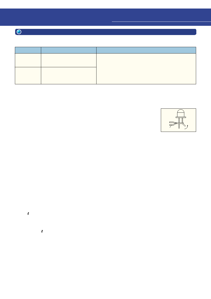
44
Soldering coditions
InGaA P series LEDs are known for their high reliability compared to other LED devices and exhibit excellent charac-
teristics particularly in high-temperature, high-humidity environments. However, before using these devices in equip-
ment, be sure to perform adequate testing; in addition, include safety margins in design specifications.
The new InGaA P-type U-Series uses tin (Sn) plating instead of solder dip as the sheathing for leads.
Lead-free (Pb-free) sheathing helps to preserve the environment. When using this series, please note the following:
1) The solderability of tin plate is equivalent to that of solder dip. However, avoid storing U-Series devices for long
periods and try to use them as soon as possible.
2) Since there is exposed iron (Fe) on the cut section of the lead tie-bar, leads may get rusty. Treat (protect) the surface
of leads where necessary, particularly when devices are to be used in salty environments.
For detailed recommended storage conditions, see the usage cautions in the databook.
Toshiba plan to introduce lead-free (Pb-free) sheathing of leads gradually for conventional LEDs as well.
The lead should be formed at least 5 mm away from the body of the device.
Care must be taken to ensure that no stress is applied to the resin.
Mechanical stress on leads
If stress is applied to leads during soldering, or if excessive stress such as tension, twisting or compression is applied
between leads while the temperature is still high immediately after soldering the device may be open circuited and will
afterwards be unable to perform according to its specifications. Instead, positions and directions of leads must be cor-
rected after cooling.
This type of visible LED lamp also emits some IR light. If a photodetector is located near the LED lamp, please ensure that
it will not be affected by this IR light.
Pliers
q
Soldering precaution for TLRME68TG Series
Type of soldering
Conditions
Precautions
Solder dip
Manual
soldering (using
soldering iron)
Solder temperature: 260
∞
C max
Dipping time: 3 seconds max
Soldering portion of lead: at least 2 mm
away from the body of the device
Iron tip temperature: 300
∞
C max
Soldering iron capacity: 30 W max
Soldering time: 3 seconds max
Soldering portion of lead: at least 2 mm
away from the body of the device
When the temperature of the device itself is rising, please be careful
not to apply mechanical stress to it.
During solder dip, do not apply mechanical stress between leads of a
device; measures should taken especially in order to prevent tempera-
ture rise in a device.
It is recommended to radiate heat by gripping leads with pliers or a
tweezer when the working condition permits doing so.
1. Lead Type
1-1 Mounting on a Printed Circuit Board (PCB)
1-2 Mounting Precautions
1-3 Reliability
1-4 U-Series Lead Sheathing
1-5 Four-element LEDs
6
Handling Precautions
Lead forming
Cleaning
1) Ultrasonic cleaning
The resin material of the device package may be harmed if ultrasonic cleaning is conducted after soldering and a
solvent is used remove flux, or if non-recommended chemicals are used for brusing.
Note:
The amount of stress applied to a device during ultrasonic cleaning will vary according to the size of the cleaning tank, the output power of
the oscillator, the size of the PCB, and the mounting method. Please confirm test results under actual conditions before starting cleanig in
production line.
Ultrasonic cleaning should normally be conducted with an ultrasonic output of 300 W or lower and should be completed within 30 seconds.
These requirements may vary according to the size of the cleaning tank and the PCB.
2) Solvent
Depending on the solvent used, the sealed resin of a device package may be harmed. It is therefore necessary to
confirm in advance that the solvent used for cleaning will not harm the resin. (Also, the use of solvents containing
freon is restricted so as to prevent destruction of the ozone layer.) Before using any chemical, check whether the
solvent will harm the device package resin.
q
q
q
These newly designed LED lamps are less prone to the effects of stress during automatic mounting than conventional
LED lamps. Hence, this type of LED lamp can be mounted close to a through-hole on the PCB. However, if one of these
lamps is subjected to excessive stress, the resin part may break or the lamp may be damaged in such a way that it will not
emit light. Before using this type of LED lamp, please carefully read the technical datasheets for the product in question.
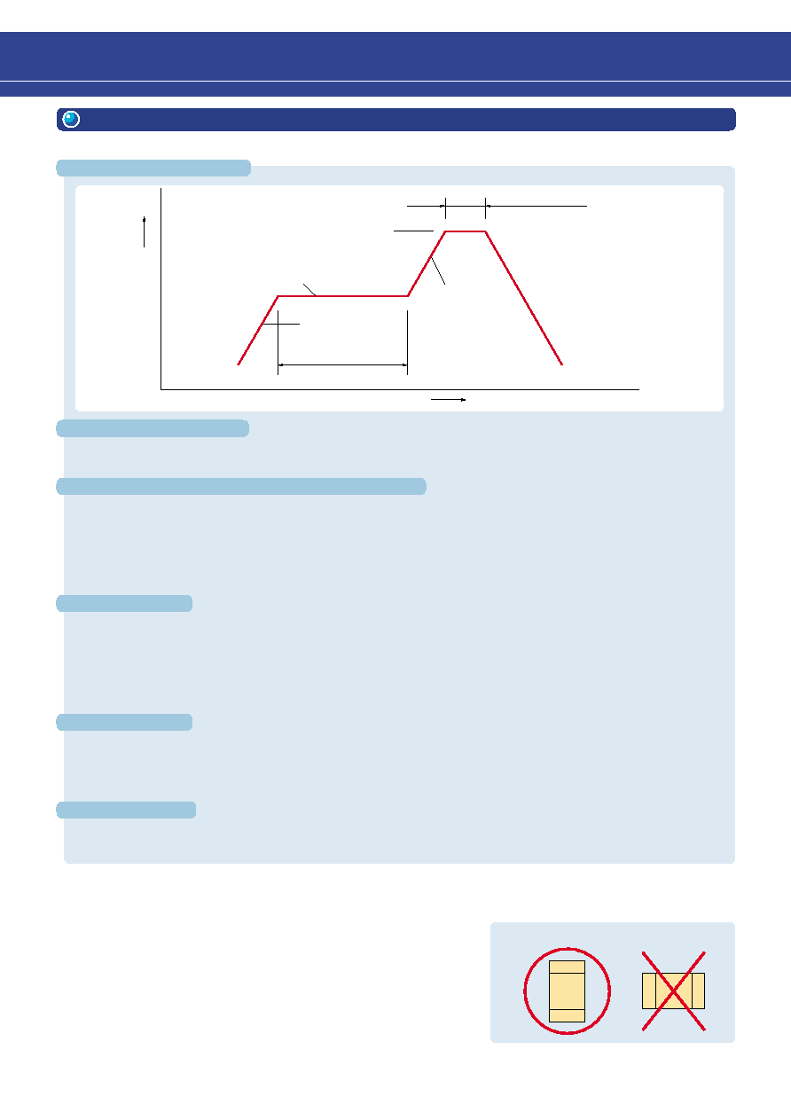
45
Temperature profile (reflow)
10 s max
240
∞
C max
140
∞
C~160
∞
C
4
∞
C / s max
4
∞
C / s max
Time (s)
Temp.(
∞
C)
60~120 s
PCB
Based on the specifications of the individual product.
Please refer to each datasheets. (Page 28, 30, 32, 34 and 36)
2. SMD Type
2-1 Recommended Soldering Conditions
Manual soldering
Soldering pad dimensions
∑ Please perform the first reflow soldering with reference to the above temperature profile within 168 h after package is
opened.
∑ Please ask your nearest Toshiba distributor for more details before performing repeat reflow soldering.
∑ Do not perform flow soldering.
Manual soldering should be performed within 3 s at a maximum temperature of 300
∞
C using a 25 W soldering iron.
Manual soldering should be performed only once at each soldering spot.
2-2 Mounting Precautions
∑ Do not apply stress to the resin part at high temperature.
∑ The resin can easily be scratched. Avoid friction between the resin and any hard materials.
∑ When installing the PCB in a product, ensure that the device does
not come into contact with other components.
∑ The product should be mounted widthwise on the PCB is across the
width of the board.
∑ Design the PCB layout so as to minimize force which will be exerted
on the device if the PCB warps.
∑ When the device is mounted on a flexible PCB, before using the
product, ensure that there is no problem with LED reliability.
Mounting example
∑ Please perform the first reflow soldering with reference to the above temperature profile within 168 h after package is
opened.
∑ If a second reflow soldering, it should be performed within 168 h of the first reflow under the above temperature profile
conditions.
∑ Storage conditions before second reflow soldering: 30
∞
C, 60% RH or lower
∑ Please ask your nearest Toshiba distributor for more details before performing flow soldering.
s
TL
1102 Series
s
TL
1100 Series
∑ Please perform the first reflow soldering with reference to the above temperature profile within 168 h after package is
opened.
∑ If a second reflow soldering, it should be performed within 168 h of the first reflow under the above temperature profile
conditions.
∑ Storage conditions before second reflow soldering: 30
∞
C, 60% RH or lower
∑ Do not perform flow soldering.
s
TL
1002A Series, TL
1005B Series, TL
1008A Series

46
When cleaning is required after soldering
2-3 Moisture-Proof Packaging
To avoid moisture absorption by the resin, the devices are packed in an
aluminum envelope with silica gel.
Because the optical characteristics of the device can be affected during
soldering due to gas expansion resulting from previous moisture
absorption, store under the following conditions after opening.
Chemical
Temperature and time
Ultrasonic cleaning
AK225, alcohol
50
∞
C x 30 s and 30
∞
C x 30 mins
300 W or less
0.5
1
6
Handling Precautions
Caution:
1. The moisture proof bag may be stored unopened within
6 months at the following conditions.
Temperature: 5
∞
C~30
∞
C
Humidity: 90% (max)
2. After opening the moisture proof bag, the devices should
be assembled within 168 hours in an environment of 5
∞
C
to 30
∞
C / 60% RH or below.
3. If upon opening, the moisture indicator card shows
humidity 30% or above (Color of indication changes to
pink) or the expiration date has passed, the devices
should be baked in taping with reel.
After baking, use the baked devices within 72 hours, but
perform baking only once.
Baking conditions: 60
∞
C
±
5
∞
C, for 12 to 24 hours.
Expiration date: 6 months from sealing date, which is
imprinted on the same side as this label affixed.
4. Repeated baking can cause the peeling strength of the
taping to change, than leads to trouble in mounting.
Furthermore, prevent the devices from being destructed
against static electricity for baking of it.
5. If the packing material of laminate would be broken, the
hermeticity would deteriorate. Therefore, do not throw or
drop the packed devices.
2-4 Design Precautions (for the LEDs general characteristics)
Adhere strictly to maximum ratings
The maximum ratings are a set of specified values which must not be exceeded, even for an instant.
For the ratings of a specific device, please refer to the individual specifications for the device in question.
Adhere strictly to the temperature range in which operations are guaranteed.
The recommended operating conditions for each device are those necessary to guarantee that the device will
operate as specified in the datasheets. To ensure high reliability when using the device, derate the maximum
ratings for current, power and temperature as recommended in the individual specifications for the device in
question.
Temperature and humidity environment
Compared to mechanical components, semiconductor devices are generally highly sensitive to temperature.
Since a the device's electrical characteristics are subject to the usage temperature, first investigate the
product's temperature characteristics, and, if necessary, incorporate derating into the design.
If the device is used outside the guaranteed operating temperature range, its electrical characteristics cannot
be guaranteed and performance deterioration may result.
Viewing angle characteristic
Each product has its own distinct viewing angle characteristic.
Select the product whose viewing angle characteristic best meets the
requirements for the device in which it will be used.
The viewing angle is based on the angle q between the axis on which
the luminous intensity of light from the optical source is 100% and any
axis on which the luminous intensity is 50%.
The angle between these two axes is referred to as the LED's half-
angle value.
For the viewing angle characteristic of a particular product, please
refer to the datasheets for the product in question.

47
10
5
3
1
0.5
0.3
0.1
≠30
≠10
10
30
50
70
I
V
-T
C
Relative Luminous Intensity Iv
Case Temperature Tc (
∞
C)
Example: Temperature dependence of optical output
150
100
50
INT.
100
1000
10000
100000
Test Condition: I
F
= 25 mA, Duty = 100%, Ta = 25
∞
C, N = 30
Relative Luminous Intensity (%)
Test Time (h)
TLOE1002 Operation life test
Thermal design precautions
The failure rate of semiconductor devices is greatly accelerated by high operating temperatures.
Ensure that the ambient temperature (Ta) of the device is not affected by exothermic heat in the device's
vicinity, and that the ambient temperature is kept as low as possible.
If the device's operating power dissipation is comparatively large, consider forced-air cooling, the selection of
different PCB materials, or the use of heat-dispersion sink, for example. These measures can lower the
thermal resistance of the package.
Temperature dependence
Luminance
Because the light recoupling rate of the LED is
temperature dependent, as the temperature rises, the
intensity of the light emission falls. To avoid a temperature
rise in the connection resulting from power dissipation,
Toshiba recommends a pulse driving design and a case
with good heat dispersion characteristics. Before using the
device, check that there are no problems with set use.
Color tone (Light emission wavelength)
In LEDs, a temperature rise in the junction resulting from
power dissipation causes the light emission wavelength to shift to the longer side. Toshiba therefore
recommends a thermal design that avoids temperature rise in the junction due to power dissipation.
Reference value:
= 0.2 nm x
Tj
Tj: Emitted-light device junction temperature
Light output deterioration
The lifespan of the emitted-light device is greatly affected not only by the device's own particular lifespan
characteristics, but by the operating conditions and the operating environment as well. Accordingly, when
selecting the emitted-light device and setting the operating conditions, we recommend checking first the several
characteristics affecting lifespan.
For reliability data on individual products, including lifespan data, inquire at a Toshiba sales office or agency.
q
Visible LED lamps made of will also emit some IR light. If a photodetector is located near an LED lamp,
please ensure that it will not be affected by this IR light.
InGaA P
∑
∑
∑
∑
48
With Lead Stopper Type
Straight Type
With Lead Stopper Type
Straight Type
With Lead Stopper Type
Straight Type
S4E38XX(T)
TLGE11T(T)
TLGE158(T)
TLGE159(T)
TLGE174(T)
TLGE183(T)
TLGE18C(T)
TLGE18T(T)
TLGE19T(T)
TLGE23T(T)
TLGE25T(T)..
TLGE260(T)
TLGE262(T)
TLGE27C(T)
TLGE50T(T)
TLGE53C(T)
TLGE53T(T)
TLGE60T(T)
TLGE62T(T)
TLOE11T(T)
TLOE156A(T)
TLOE157A(T)
TLOE16C(T)
TLOE16T(T)
TLOE17T(T)
TLOE180A(T)
TLOE20T(T)
TLOE25T(T)
TLOE266(T)
TLOE27C(T)
TLOE50T(T)
TLOE53T(T)
TLOE60T(T)
TLOE62T(T)
TLOH156(T)
TLOH157(T)
TLOH180(T)
TLGE11TP(T)
TLGE158P(T)
TLGE159P(T)
TLGE174P(T)
TLGE183P(T)
TLGE18CP(T)
TLGE18TP(T)
TLGE19TP(T)
TLGE23TP(T)
TLGE25TP(T)
TLOE11TP(T)
TLOE156AP(T)
TLOE157AP(T)
TLOE16CP(T)
TLOE16TP(T)
TLOE17TP(T)
TLOE180AP(T)
TLOE20TP(T)
TLOE25TP(T)
TLOE266P(T)
TLOH156P(T)
TLOH157P(T)
TLOH180P(T)
TLPGE11T(T)
TLPGE158(T)
TLPGE159(T)
TLPGE183(T)
TLPGE18T(T)
TLPGE19T(T)
TLPGE23T(T)
TLPGE50T(T)
TLPGE53T(T)
TLPGE62T(T)
TLRE11T(T)
TLRE156A(T)
TLRE157A(T)
TLRE16C(T)
TLRE16T(T)
TLRE17T(T)
TLRE180A(T)
TLRE20T(T)
TLRE25T(T)
TLRE27C(T)
TLRE50T(T)
TLRE53T(T)
TLRE60T(T)
TLRE62T(T)
TLRH156(T)
TLRH157(T)
TLRH180(T)
TLRH262(T)
TLRME16C(T)
TLRME16T(T)
TLRME17D(T)
TLRME17T(T)
TLRME20T(T)
TLRME27C(T)
TLRME50T(T)
TLRME53T(T)
TLRME62T(T)
TLRMH151(T)
TLRMH156(T)
TLRMH157(T)
TLSE156(T)
TLSE157(T)
TLSE16C(T)
TLSE16T(T)
TLSE17T(T)
TLSE180(T)
TLSE20T(T)
TLSE27C(T)
TLSE50T(T)
TLSE53T(T)
TLSE62T(T)
TLSH156(T)
TLSH157(T)
TLSH180(T)
TLYE11T(T)
TLYE156A(T)
TLYE157A(T)
TLYE16C(T)
TLYE16T(T)
TLYE17T(T)
TLYE180A(T)
TLYE20T(T)
TLYE25T(T)
TLYE260A(T)
TLYE262A(T)
TLYE27C(T)
TLYE50T(T)
TLYE53T(T)
TLYE60T(T)
TLYE62T(T)
TLYH151(T)
TLYH156(T)
TLYH157(T)
TLYH180(T)
TLPGE11TP(T)
TLPGE158P(T)
TLPGE159P(T)
TLPGE183P(T)
TLPGE18TP(T)
TLPGE19TP(T)
TLPGE23TP(T)
TLRE11TP(T)
TLRE156AP(T)
TLRE157AP(T)
TLRE16CP(T)
TLRE16TP(T)
TLRE17TP(T)
TLRE180AP(T)
TLRE20TP(T)
TLRE25TP(T)
TLRH156P(T)
TLRH157P(T)
TLRH180P(T)
TLRME16CP(T)
TLRME16TP(T)
TLRME17DP(T)
TLRME17TP(T)
TLRME20TP(T)
TLRMH151P(T)
TLRMH156P(T)
TLRMH157P(T)
TLSE156P(T)
TLSE157P(T)
TLSE16CP(T)
TLSE16TP(T)
TLSE17TP(T)
TLSE180P(T)
TLSE20TP(T)
TLSH156P(T)
TLSH157P(T)
TLSH180P(T)
TLYE11TP(T)
TLYE156AP(T)
TLYE157AP(T)
TLYE16CP(T)
TLYE16TP(T)
TLYE17TP(T)
TLYE180AP(T)
TLYE20TP(T)
TLYE25TP(T)
TLYH151P(T)
TLYH156P(T)
TLYH157P(T)
TLYH180P(T)
Place of Manufacture: Toshiba Semiconductor Thailand Co., Ltd.
Abbreviation: TST
Manufactured products: High-brightness lead-type LED lamps
The suffix ` T ' in brackets at the end of a product number indicates that the product was manufactured by
Toshiba Semiconductor Thailand Co., Ltd. The luminosity rank for the product, if there is one, is also specified
within the brackets, before the suffix ` T '.
∑ Example: TLRH157P (TU, T)
The product number above indicates that the product was manufactured in Thailand and that it is available with
luminosity ranks of T and U.
If your products are assembled outside Japan, high-brightness lead-type LED lamps can be supplied by
Toshiba Semiconductor Thailand Co., Ltd. upon request.
For information about Thai-manufactured products, please contact your nearest Toshiba distributor.
7
Product Manufactured Overseas
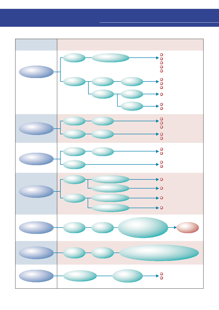
49
Brightness
Directivity
Reliability
Package Size
Luminance
Fluctuation
Color
Fluctuation
Low-Power
Consumption
TL
E1002A Series
TL
E1008A Series
TL
1002A Series
TL
U1005A Series
TL
E1005A Series
TL
1102 Series
TL
U1002A Series
TL
E1002A Series
TL
U1008A Series
TL
E1008A Series
TL
1100 Series
TL
U1002A Series
TL
E1002A Series
Miniature battery-
operated equipment
Low-current driving
TL
1005B Series
TL
1102 Series
TL
1002A Series
TL
1008A Series
TL
1100 Series
TL
1002A Series
TL
1008A Series
TL
1005B Series
2.0
X
1.25
X
1.1 mm
1.6
X
0.8
X
0.6 mm
All products
One rank width set
in accordance with the
sensitivity of the human eye.
Normally selected to within
two ranks.
Wavelength
rank selection
in surface
Nonuniformity
in surface
Selections in the dominant
wavelength (
d) can be made on request.
Inquire at a Toshiba sales office.
Conditions required
in applications
Recommend LED Lamp Series
TL
E1002A Series
TL
E1008A Series
TL
1102 Series
3.2
X
2.4
X
2.4 mm
with ¯2 lens
3.2
X
2.8
X
3.4 mm
with ¯2.8 lens
Used for backlight
LED direct
Narrow
directivity
Wide
directivity
High intensity
application
High intensity
application
Low intensity
application
High intensity /
wide directivity
Used for backlight
LED
directly viewed
For display
TL
1100 Series
TL
1102 Series
For automotive
Long term
operation
Medium to wide
directivity
Wide directivity
Replacement
for lead type
Miniature / slim
Nonuniformity
in surface
Luminance
rank selection
in surface
q
Considerations for Selecting of SMD Lamps
8
Application Note
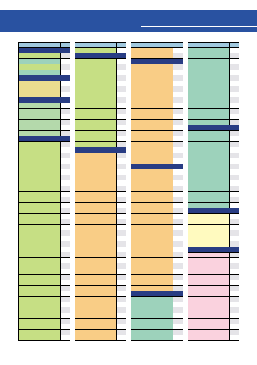
50
Product Number
Page
q
S4F
Series
S4F42Q1(T09)
S4F42Z1(T09)
S4F43Q1(T10)
S4F43Z1(T10)
q
TLAU
Series
TLAU1002A(T02)
TLAU1008A(T04)
TLAU1008A(T05)
q
TLFGE
Series
TLFGE18TP
TLFGE19TP
TLFGE23TP
TLFGE50T
TLFGE53T
TLFGE62T
q
TLGE
Series
TLGE1002A(T02)
TLGE1005B(T03)
TLGE1008A(T04)
TLGE1008A(T05)
TLGE1100(T11)
TLGE1102(T10)
TLGE11TP
TLGE123
TLGE123(PQ)
TLGE125
TLGE125(QR)
TLGE158P
TLGE158P(QR)
TLGE159P
TLGE159P(ST)
TLGE160
TLGE160(TU)
TLGE174P
TLGE183P
TLGE18CP
TLGE18TP
TLGE19TP
TLGE23TP
TLGE247
TLGE247(PQ)
TLGE248
TLGE25TP
TLGE260
TLGE260(KL)
TLGE262
TLGE262(NP)
TLGE27C
TLGE50T
TLGE53T
TLGE60T
TLGE62T
34
34
36
36
30
28
28
22
22
22
22
22
22
30
32
28
28
34
36
22
22
22
22
22
22
22
22
22
22
22
22
22
22
22
22
22
22
22
22
22
22
22
22
22
22
22
22
22
22
Product Number
Page
TLGE68TG
q
TLGU
Series
TLGU1002A(T02)
TLGU1008A(T04)
TLGU1008A(T05)
TLGU1100(T09)
TLGU1102(T10)
TLGU13CP
TLGU13DP
TLGU18CP
TLGU18TP
TLGU23TP
TLGU27C
TLGU50T
TLGU53C
TLGU53D
TLGU53T
TLGU62T
q
TLOE
Series
TLOE1002A(T02)
TLOE1005B(T03)
TLOE1008A(T04)
TLOE1008A(T05)
TLOE1100(T11)
TLOE1102(T10)
TLOE11TP
TLOE156AP
TLOE156AP(RS)
TLOE157AP
TLOE157AP(ST)
TLOE160A
TLOE160A(ST)
TLOE16CP
TLOE16TP
TLOE17TP
TLOE180AP
TLOE180AP(UV)
TLOE20TP
TLOE248
TLOE25TP
TLOE260A
TLOE260A(LM)
TLOE261AP
TLOE261AP(LM)
TLOE262A
TLOE262A(PQ)
TLOE263AP
TLOE263AP(PQ)
TLOE266
TLOE266(RS)
TLOE27C
TLOE50T
TLOE53T
22
30
28
28
34
36
24
24
24
24
24
24
24
24
24
24
24
30
32
28
28
34
36
18
18
18
18
18
18
18
18
18
18
18
18
18
18
18
18
18
18
18
18
18
18
18
18
18
18
18
18
Product Number
Page
TLOE60T
TLOE62T
q
TLOH
Series
TLOH1100(T09)
TLOH1102(T10)
TLOH156P
TLOH156P(ST)
TLOH157P
TLOH157P(TU)
TLOH160
TLOH160(TU)
TLOH16TP
TLOH17TP
TLOH180P
TLOH180P(VW)
TLOH190P
TLOH190P(XY)
TLOH20TP
TLOH262
TLOH262(PQ)
TLOH38TP
q
TLOU
Series
TLOU1002A(T02)
TLOU1005A(T03)
TLOU1008A(T04)
TLOU1008A(T05)
TLOU1100(T09)
TLOU1102(T10)
TLOU113P
TLOU113P(RS)
TLOU114P
TLOU114P(NP)
TLOU123
TLOU124
TLOU156P
TLOU156P(RS)
TLOU160
TLOU172P
TLOU180P
TLOU180P(UV)
TLOU248
TLOU262
TLOU262(PQ)
TLOU267
q
TLPGE
Series
TLPGE1002A(T02)
TLPGE1005B(T03)
TLPGE1008A(T04)
TLPGE1008A(T05)
TLPGE1100(T11)
TLPGE1102(T10)
TLPGE11TP
TLPGE125
18
18
34
36
18
18
18
18
18
18
18
18
18
18
18
18
18
18
18
18
30
32
28
28
34
36
18
18
18
18
18
18
18
18
18
18
18
18
18
18
18
18
30
32
28
28
34
36
22
22
Product Number
Page
TLPGE158P
TLPGE159P
TLPGE160
TLPGE183P
TLPGE183P(ST)
TLPGE18TP
TLPGE19TP
TLPGE23TP
TLPGE247
TLPGE247(LM)
TLPGE262
TLPGE50T
TLPGE53T
TLPGE62T
q
TLPGU
Series
TLPGU1002A(T02)
TLPGU1008A(T04)
TLPGU1008A(T05)
TLPGU1100(T09)
TLPGU1102(T10)
TLPGU13CP
TLPGU13DP
TLPGU18TP
TLPGU23TP
TLPGU50T
TLPGU53C
TLPGU53D
TLPGU53T
TLPGU62T
q
TLPYE
Series
TLPYE18T
TLPYE19TP
TLPYE23TP
TLPYE50T
TLPYE53T
TLPYE62T
q
TLRE
Series
TLRE1002A(T02)
TLRE1005B(T03)
TLRE1008A(T04)
TLRE1008A(T05)
TLRE1100(T11)
TLRE1102(T10)
TLRE11TP
TLRE138P
TLRE156AP
TLRE156AP(PQ)
TLRE157AP
TLRE157AP(RS)
TLRE160A
TLRE160A(RS)
TLRE16CP
TLRE16TP
22
22
22
22
22
22
22
22
22
22
22
22
22
22
30
28
28
34
36
24
24
24
24
24
24
24
24
24
20
20
20
20
20
20
30
32
20
20
34
36
16
16
16
16
16
16
16
16
16
16
9
Product Number Index
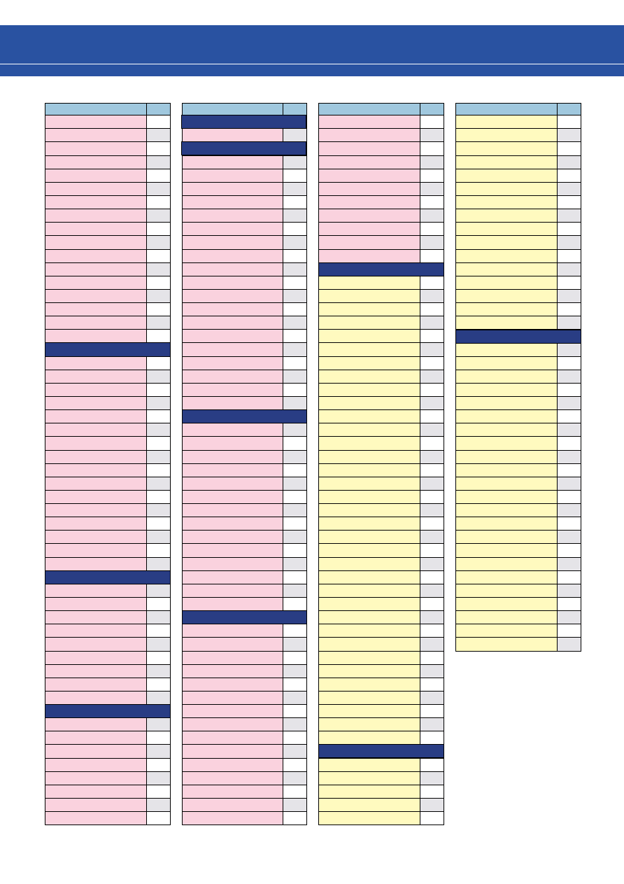
51
Product Number
Page
TLRE17TP
TLRE180AP
TLRE180AP(TU)
TLRE20TP
TLRE248
TLRE25TP
TLRE260A
TLRE261AP
TLRE262A
TLRE262A(MN)
TLRE263AP
TLRE263AP(MN)
TLRE27C
TLRE50T
TLRE53T
TLRE60T
TLRE62T
q
TLRH
Series
TLRH1100(T09)
TLRH1102(T10)
TLRH156P
TLRH156P(QR)
TLRH157P
TLRH157P(ST)
TLRH160
TLRH160(ST)
TLRH180P
TLRH180P(UV)
TLRH190P
TLRH190P(WX)
TLRH247
TLRH247(PQ)
TLRH262
TLRH262(NP)
q
TLRME
Series
TLRME16TP
TLRME17DP
TLRME17TP
TLRME20TP
TLRME27C
TLRME50T
TLRME53T
TLRME62T
TLRME68TG
q
TLRMH
Series
TLRMH151P
TLRMH156P
TLRMH157P
TLRMH16TP
TLRMH17TP
TLRMH20TP
TLRMH265P
TLRMH38TP
16
16
16
16
16
16
16
16
16
16
16
16
16
16
16
16
16
16
34
36
14
14
14
14
14
14
14
14
14
14
14
14
14
14
16
16
16
16
16
16
16
16
16
14
14
14
14
14
14
14
14
Product Number
Page
q
TLRU
Series
TLRU1002A(T02)
q
TLSE
Series
TLSE1002A(T02)
TLSE1005B(T03)
TLSE1008A(T04)
TLSE1008A(T05)
TLSE1100(T11)
TLSE1102(T10)
TLSE156P
TLSE156P(RS)
TLSE157P
TLSE157P(ST)
TLSE16CP
TLSE16TP
TLSE17TP
TLSE180P
TLSE20TP
TLSE27C
TLSE50T
TLSE53T
TLSE62T
q
TLSH
Series
TLSH1100(T09)
TLSH1102(T10)
TLSH125
TLSH156P
TLSH156P(RS)
TLSH157P
TLSH157P(ST)
TLSH160
TLSH16TP
TLSH17TP
TLSH180P
TLSH180P(VW)
TLSH20TP
TLSH38TP
q
TLSU
Series
TLSU1002A(T02)
TLSU1005A(T03)
TLSU1008A(T04)
TLSU1008A(T05)
TLSU1100(T09)
TLSU1102(T10)
TLSU113P
TLSU114P
TLSU114P(NP)
TLSU123
TLSU123(PQ)
TLSU124
TLSU124(MN)
TLSU125
TLSU125(PQ)
30
30
32
28
28
34
36
16
16
16
16
16
16
16
16
16
16
16
16
16
34
36
14
14
14
14
14
14
14
14
14
14
14
14
30
32
28
28
34
36
14
14
14
14
14
14
14
14
14
Product Number
Page
TLSU126
TLSU156P
TLSU156P(QR)
TLSU160
TLSU163
TLSU164
TLSU180P
TLSU180P(TU)
TLSU262
TLSU262(NP)
TLSU268G
q
TLYE
Series
TLYE1002A(T02)
TLYE1005B(T03)
TLYE1008A(T04)
TLYE1008A(T05)
TLYE1100(T11)
TLYE1102(T10)
TLYE11TP
TLYE156AP
TLYE156AP(QR)
TLYE157AP
TLYE157AP(ST)
TLYE160A
TLYE160A(ST)
TLYE16CP
TLYE16TP
TLYE17TP
TLYE18TP
TLYE180AP
TLYE180AP(UV)
TLYE20TP
TLYE25TP
TLYE260A
TLYE260A(KL)
TLYE261AP
TLYE261AP(JK)
TLYE262A
TLYE262A(NP)
TLYE263AP
TLYE263AP(NP)
TLYE27C
TLYE50T
TLYE53T
TLYE60T
TLYE62T
TLYE68TG
q
TLYH
Series
TLYH1100(T09)
TLYH1102(T10)
TLYH151P
TLYH156P
TLYH156P(RS)
14
14
14
14
14
14
14
14
14
14
14
30
32
28
28
34
36
20
20
20
20
20
20
20
20
20
20
20
20
20
20
20
20
20
20
20
20
20
20
20
20
20
20
20
20
20
34
36
20
20
20
Product Number
Page
TLYH157P
TLYH157P(TU)
TLYH160
TLYH160(TU)
TLYH16TP
TLYH17TP
TLYH180P
TLYH180P(VW)
TLYH190P
TLYH190P(XY)
TLYH20TP
TLYH247
TLYH247(QR)
TLYH262
TLYH262(PQ)
TLYH38TP
q
TLYU
Series
TLYU1002A(T02)
TLYU1005A(T03)
TLYU1008A(T04)
TLYU1008A(T05)
TLYU1100(T09)
TLYU1102(T10)
TLYU113P
TLYU114P
TLYU114P(MN)
TLYU123
TLYU123(NP)
TLYU124
TLYU124(MN)
TLYU156P
TLYU156P(QR)
TLYU160
TLYU160(ST)
TLYU172P
TLYU180P
TLYU180P(TU)
TLYU262
TLYU262(MN)
TLYU267
20
20
20
20
20
20
20
20
20
20
20
20
20
20
20
20
30
32
28
28
34
36
20
20
20
20
20
20
20
20
20
20
20
20
20
20
20
20
20

©2001 TOSHIBA CORPORATION
Printed in Japan
OVERSEAS SUBSIDIARIES AND AFFILIATES
Toshiba America
Electronic Components, Inc.
Headquarters-Irvine, CA
9775 Toledo Way, Irvine, CA 92618, U.S.A.
Tel: (949)455-2000 Fax: (949)859-3963
Boulder, CO
3100 Arapahoe Avenue, Ste. 500,
Boulder, CO 80303, U.S.A.
Tel: (303)442-3801 Fax: (303)442-7216
Boynton Beach, FL(Orlando)
11924 W. Forest Hill Blvd., Ste. 22-337,
Boynton Beach, FL 33414, U.S.A.
Tel: (561)374-6193 Fax: (561)374-6194
Deerfield, IL(Chicago)
One Pkwy., North, Suite 500, Deerfield,
IL 60015-2547, U.S.A.
Tel: (847)945-1500 Fax: (847)945-1044
Duluth, GA(Atlanta)
3700 Crestwood Parkway, Ste. 460,
Duluth, GA 30096, U.S.A.
Tel: (770)931-3363 Fax: (770)931-7602
Edison, NJ
2035 Lincoln Hwy. Ste. #3000, Edison
NJ 08817, U.S.A.
Tel: (732)248-8070 Fax: (732)248-8030
Orange County, CA
2 Venture Plaza, #500 Irvine, CA 92618, U.S.A.
Tel: (949)453-0224 Fax: (949)453-0125
Portland, OR
1700 NW 167th Place, #240,
Beaverton, OR 97006, U.S.A.
Tel: (503)629-0818 Fax: (503)629-0827
Raleigh, NC
5511 Capitol Center Dr., #114,
Raleigh, NC 27606, U.S.A.
Tel: (919)859-2800 Fax: (919)859-2898
Richardson, TX(Dallas)
777 East Campbell Rd., Suite 650, Richardson,
TX 75081, U.S.A.
Tel: (972)480-0470 Fax: (972)235-4114
San Jose Engineering Center, CA
1060 Rincon Circle, San Jose, CA 95131, U.S.A.
Tel: (408)526-2400 Fax:(408)526-2410
Wakefield, MA(Boston)
401 Edgewater Place, Suite #360, Wakefield,
MA 01880-6229, U.S.A.
Tel: (781)224-0074 Fax: (781)224-1095
Toshiba Do Brasil S.A.
Electronic Components Div.
Estrada Dos Alvarengas, 5. 500-Bairro Alvarenga
09850-550-Sao Bernardo do campo - SP
Tel: (011)7689-7171 Fax: (011)7689-7189
Toshiba Electronics Europe GmbH
D¸sseldorf Head Office
Hansaallee 181, D-40549 D¸sseldorf
Germany
Tel: (0211)5296-0 Fax: (0211)5296-400
M¸nchen Office
B¸ro M¸nchen Hofmannstrasse 52,
D-81378, M¸nchen, Germany
Tel: (089)748595-0 Fax: (089)748595-42
Toshiba Electronics France SARL
Immeuble Robert Schumann 3 Rue de Rome,
F-93561, Rosny-Sous-Bois, Cedex, France
Tel: (1)48-12-48-12 Fax: (1)48-94-51-15
Toshiba Electronics Italiana S.R.L.
Centro Direzionale Colleoni
Palazzo Perseo Ingr. 2-Piano 6,
Via Paracelso n.12,
1-20041 Agrate Brianza Milan, Italy
Tel: (039)68701 Fax:(039)6870205
Toshiba Electronics EspaÒa, S.A.
Parque Empresarial San Fernando Edificio Europa,
1
a
Planta, ES-28831 Madrid, Spain
Tel: (91)660-6700 Fax:(91)660-6799
Toshiba Electronics(UK) Limited
Riverside Way, Camberley Surrey,
GU15 3YA, U.K.
Tel: (01276)69-4600 Fax: (01276)69-4800
Toshiba Electronics Scandinavia AB
Gustavslundsv‰gen 12, 2nd Floor
S-161 15 Bromma, Sweden
Tel: (08)704-0900 Fax: (08)80-8459
Toshiba Electronics Asia
(Singapore) Pte. Ltd.
Singapore Head Office
438B Alexandra Road, #06-08/12 Alexandra
Technopark, Singapore 119968
Tel: (278)5252 Fax: (271)5155
Bangkok Office
135 Moo 5 Bangkadi Industrial Park, Tivanon Rd.,
Bangkadi Amphur Muang Pathumthani, Bangkok, 12000,
Thailand
Tel: (02)501-1635 Fax: (02)501-1638
Toshiba Electronics Trading
(Malaysia)Sdn. Bhd.
Kuala Lumpur Head Office
Suite W1203, Wisma Consplant, No.2,
Jalan SS 16/4, Subang Jaya, 47500 Petaling Jaya,
Selangor Darul Ehsan, Malaysia
Tel: (3)731-6311 Fax: (3)731-6307
Penang Office
Suite 13-1, 13th Floor, Menard Penang Garden,
42-A, Jalan Sultan Ahmad Shah,
100 50 Penang, Malaysia
Tel: 4-226-8523 Fax: 4-226-8515
Toshiba Electronics Philippines, Inc.
26th Floor, Citibank Tower, Valero Street, Makati,
Manila, Philippines
Tel: (02)750-5510 Fax: (02)750-5511
Toshiba Electronics Asia, Ltd.
Hong Kong Head Office
Level 11, Top Glory Insurance Building, Grand Century
Place, No.193, Prince Edward Road West,
Mong Kok, Kowloon, Hong Kong
Tel: 2375-6111 Fax: 2375-0969
Beijing Office
Rm 714, Beijing Fortune Building,
No.5 Dong San Huan Bei-Lu, Chao Yang District,
Beijing, 100004, China
Tel: (010)6590-8795 Fax: (010)6590-8791
Chengdu Office
Unit F, 18th Floor, New Times Plaza, 42 Wenwu Road,
Xinhua Avenue, Chengdu, 610017, China
Tel: (028)675-1773 Fax: (028)675-1065
Shenzhen Office
Rm 3010-3012, Office Tower Shun Hing Square,
Di Wang Commercial Centre, 333 ShenNan
East Road, Shenzhen, 518008, China
Tel: (0755)246-1582 Fax: (0755)246-1581
Toshiba Electronics Korea Corporation
Seoul Head Office
14/F, KEC B/D, 257-7 Yangjae-Dong,
Seocho-ku, Seoul, Korea
Tel: (02)589-4334 Fax: (02)589-4302
Gumi Office
6/F, Ssangyong Investment Securities B/D,
56 Songjung-Dong, Gumi City
Kyeongbuk, Korea
Tel: (82)54-456-7613 Fax: (82)54-456-7617
Toshiba Technology Development
(Shanghai) Co., Ltd.
23F, Shanghai Senmao International Building, 101
Yin Cheng East Road, Pudong New Area, Shanghai,
200120, China
Tel: (021)6841-0666 Fax: (021)6841-5002
Tsurong Xiamen Xiangyu Trading
Co., Ltd.
8N, Xiamen SEZ Bonded Goods Market Building,
Xiamen, Fujian, 361006, China
Tel: (0592)562-3798 Fax: (0592)562-3799
Toshiba Electronics Taiwan
Corporation
Taipei Head Office
17F, Union Enterprise Plaza Bldg. 109
Min Sheng East Rd., Section 3, 0446 Taipei,
Taiwan
Tel: (02)514-9988 Fax: (02)514-7892
Kaohsiung Office
16F-A, Chung-Cheng Bldg., Chung-Cheng 3Rd.,
80027, Kaohsiung, Taiwan
Tel: (07)222-0826 Fax: (07)223-0046
The information contained herein is subject to change without notice.
The information contained herein is presented only as a guide for the applications of our products.
No responsibility is assumed by TOSHIBA for any infringements of patents or other rights of the third parties which may result
from its use. No license is granted by implication or otherwise under any patent or patent rights of TOSHIBA or others.
TOSHIBA is continually working to improve the quality and reliability of its products. Nevertheless, semiconductor devices in
general can malfunction or fail due to their inherent electrical sensitivity and vulnerability to physical stress. It is the
responsibility of the buyer, when utilizing TOSHIBA products, to comply with the standards of safety in making a safe design for
the entire system, and to avoid situations in which a malfunction or failure of such TOSHIBA products could cause loss of
human life, bodily injury or damage to property. In developing your designs, please ensure that TOSHIBA products are used
within specified operating ranges as set forth in the most recent TOSHIBA products specifications. Also, please keep in mind
the precautions and conditions set forth in the "Handling Guide for Semiconductor Devices," or "TOSHIBA Semiconductor
Reliability Handbook" etc..
The Toshiba products listed in this document are intended for usage in general electronics applications (computer, personal
equipment, office equipment, measuring equipment, industrial robotics, domestic appliances, etc.).
These Toshiba products are neither intended nor warranted for usage in equipment that requires extraordinarily high quality and/or
reliability or a malfunction or failure of which may cause loss of human life or bodily injury ("Unintended Usage"). Unintended Usage
include atomic energy control instruments, airplane or spaceship instruments, transportation instruments, traffic signal instruments,
combustion control instruments, medical instruments, all types of safety devices, etc.. Unintended Usage of Toshiba products listed
in this document shall be made at the customer's own risk.
Website:
http://doc.semicon.toshiba.co.jp/indexus.htm
Electronic Devices Sales & Marketing Division
1-1, Shibaura 1-chome, Minato-ku, Tokyo, 105-8001, Japan
Tel: +81-3-3457-3405 Fax: +81-3-5444-9431
010124 (H)
Gallium arsenide (GaAs) is a substance used in some of the products described in this documents. GaAs dust and fumes are toxic. Do not break, cut or pulverize the products, or use chemicals to dissolve them.
When disposing of the products, follow the appropriate regulations. Do not dispose of the products with other industrial waste or with domestic garbage.