 | –≠–ª–µ–∫—Ç—Ä–æ–Ω–Ω—ã–π –∫–æ–º–ø–æ–Ω–µ–Ω—Ç: TB6539F | –°–∫–∞—á–∞—Ç—å:  PDF PDF  ZIP ZIP |
TB6539N/F
2002-06-12
1
TOSHIBA Bi-CMOS Integrated Circuit Silicon Monolithic
TB6539N,TB6539F
3-Phase Full-Wave Sine-Wave PWM Brushless Motor Control
Features
∑ Sine-wave PWM control
∑ Built-in triangular-wave generator
(carrier cycle = f
osc
/252 (Hz))
∑ Built-in lead angle control function (0 to 58∞ in 32 steps)
∑ Built-in dead time function
∑ Supports bootstrap circuit
∑ Overcurrent protection signal input pin
∑ Built-in regulator (V
refout
= 5 V (typ.), 30 mA (max))
∑ Operating supply voltage range: V
CC
= 10 to 18 V
V
M
= 4.5 to 18 V
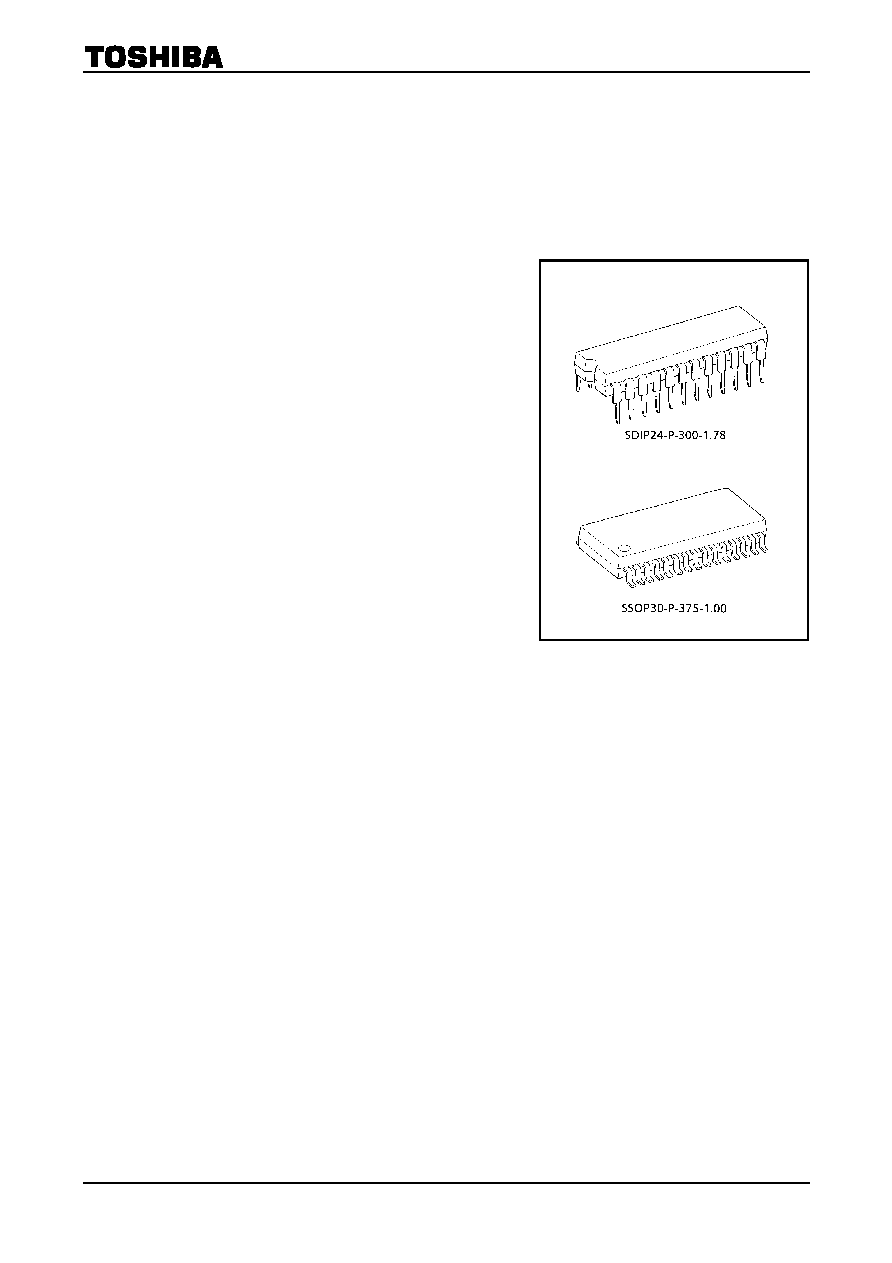
TB6539N
TB6539F
Weight
SDIP24-P-300-1.78 : 1.62 g (typ.)
SSOP30-P-375-1.00 : 0.63 g (typ.)

TB6539N/F
200
2-
06-
1
2
2
B
l
ock D
i
agr
a
m
T
h
e pin
nu
mber
s s
h
ow
n ab
ov
e are for
the
T
B
6539N
/T
B65
39F
Sy
ste
m
cl
o
c
k
generat
or
P
o
s
i
t
i
on de
t
e
ct
or
Regul
at
or
Count
er
5-bi
t
A
D
6-bi
t
t
r
i
angul
ar
w
a
ve generat
or
Out
put
wa
v
e
f
o
r
m
generat
or
Dat
a
se
l
e
c
t
Sw
itc
h
in
g
120∞
/
180∞
and
gat
e
bl
oc
k
prot
ec
t
i
on
on/
of
f
S
e
t
t
i
ng
dead
ti
m
e
Charger
120∞
-
t
u
rn-on
ma
t
r
i
x
P
o
w
e
r-on
res
e
t
P
r
ot
ect
i
on
&
res
e
t
P
has
e
m
a
t
c
hi
ng
4 bi
t
s
FG
Rot
a
t
i
ng
di
rec
t
i
o
n
ST/
S
P
CW
/
C
C
W
E
RR
GB
Com
parat
or
Com
parat
or
Com
parat
or
Com
parat
or
PW
M
HU
HV
HW
120/
180
P
has
e
W
P
has
e
U
P
has
e
V
LA
X
in
X
ou
t
HU
HV
HW
V
e
V
CC
P-
G
N
D
S-
G
N
D
V
refou
t
RE
S
I
dc
CW
/
C
C
W
FG
RE
V
14/
17
15/
19
21/
26
20/
25
19/
23
22/
27
1/
1
3/
4
13/
16
24/
30
18/
22
2/
3
17/
21
11/
14
12/
15
V
M
U
X
V
Y
W
Z
OS
4/
5
5/
6
8/
9
6/
7
9/
10
7/
8
10/
12
16/
20
23/
29
I
n
t
e
rnal
ref
e
renc
e
vol
t
a
g
e
TB6539N/F
2002-06-12
3
Pin Description
Pin No.
TB6539N TB6539F
Symbol Description
Remarks
21 26 HU
Positional signal
input pin U
20 25 HV
Positional signal
input pin V
19 13 HW
Positional signal
input pin W
When positional signal is HHH or LLL, gate block
protection operates.
With built-in pull-up resistor
17 21
CW/CCW
Rotation direction
signal input pin
L: Forward
H: Reverse
18 22 RES
Reset-signal-input
pin
L: Reset (Output is non-active)
Operation/Halt operation
Also used for gate block protection
22 27 V
e
Inputs voltage instruction
signal
With built-in pull-down resistor
23 29 LA
Lead angle setting signal
input pin
Sets 0 to 58∞ in 32 steps
16 20 OS
Inputs output logic select
signal
L: Active low
H: Active high
2 3 I
dc
Inputs overcurrent-
protection-signal
Inputs DC link current.
Reference voltage: 0.5 V
With built-in filter (
~
-
1
m
s)
14 17 X
in
Inputs clock signal
15 19 X
out
Outputs
clock
signal
With built-in feedback resistor
24 30
V
refout
Outputs reference voltage
signal
5 V (typ.), 30 mA (max)
11
14
FG
FG signal output pin
Outputs 3PPR of positional signal
12 15 REV
Reverse rotation detection
signal
Detects reverse rotation.
5 6 U
Outputs
turn-on
signal
6 7 V
Outputs
turn-on
signal
7 8 W
Outputs
turn-on
signal
8 9 X
Outputs
turn-on
signal
9 10 Y
Outputs
turn-on
signal
10 12 Z
Outputs
turn-on
signal
Select active high or active low using the output logic select pin.
1 1 V
CC
Power supply voltage pin
V
CC
=
10~18 V
4 5 V
M
Apply power supply for
output circuit.
V
M
=
4.5~18 V
3
4
P-GND
Ground for power supply
Ground pin
13
16
S-GND
Ground for signals
Ground pin

TB6539N/F
2002-06-12
4
Input/Output Equivalent Circuits
Pin Description
Symbol
Input/Output Signal
Input/Output Internal Circuit
Positional signal input pin U
Positional signal input pin V
Positional signal input pin W
HU
HV
HW
Digital
With Schmitt trigger
Hysteresis 300 mV (typ.)
L : 0.8 V (max)
H: V
refout
-
1 V (min)
Forward/reverse switching
input pin
L: Forward (CW)
H: Reverse (CCW)
CW/CCW
Digital
With Schmitt trigger
Hysteresis 300 mV (typ.)
L : 0.8 V (max)
H: V
refout
-
1 V (min)
Reset input
L: Stops operation (reset).
H: Operates.
RES
Digital
With Schmitt trigger
Hysteresis 300 mV (typ.)
L : 0.8 V (max)
H: V
refout
-
1 V (min)
Voltage instruction signal
input pin
Turn on the lower transistor
at 0.2 V or less.
(X, Y, Z pins: ON duty of
8%)
V
e
Analog
Input range 0 to 5.0 V
Input voltage of V
refout
or higher is
clipped to V
refout
.
Lead angle setting signal
input pin
0 V: 0∞
5 V: 58∞
(5-bit AD)
LA
Analog
Input range 0 to 5.0 V
Input voltage of V
refout
or higher is
clipped to V
refout
.
V
refout
100 k
9
2 k
W
V
CC
200 k
9
100
W
V
CC
200 k
9
100
W
V
refout
V
refout
200 k
9
2 k
W
V
refout
V
refout
100 k
9
2 k
W

TB6539N/F
2002-06-12
5
Pin Description
Symbol
Input/Output Signal
Input/Output Internal Circuit
Output logic select signal
input pin
L: Active low
H: Active high
OS
Digital
L : 0.8 V (max)
H: V
refout
-
1 V (min)
Overcurrent protection
signal input pin
I
dc
Analog
Gate block protected at 0.5 V or higher
(released at carrier cycle)
Clock signal input pin
X
in
Clock signal output pin
X
out
Operating range
2 to 8 MHz (crystal oscillation)
Reference voltage signal
output pin
Vrefout 5
±
0.5 V (max 30 mA)
Reverse-rotation-detection
signal output pin
REV
Digital
Open collector output: 20 mA (max)
V
CC
V
CC
V
CC
V
CC
0.
5 V
200 k
W
5 pF
Comparator
500 k
W
V
refout
V
refout
X
out
X
in
V
refout
V
refout
100 k
9
2 k
W