 | –≠–ª–µ–∫—Ç—Ä–æ–Ω–Ω—ã–π –∫–æ–º–ø–æ–Ω–µ–Ω—Ç: TMC246-PA | –°–∫–∞—á–∞—Ç—å:  PDF PDF  ZIP ZIP |

TMC246 DATA SHEET (V1.0 / Sep. 4th, 2003)
1
Copyright © 2003, TRINAMIC Microchips GmbH
TMC 246 ≠ DATA SHEET
High Current Microstep Stepper Motor Driver
with sensorless stall detection, protection /
diagnosis and SPI Interface
TRINAMIC
Æ
Microchips GmbH
Deelbˆgenkamp 4C
D ≠ 22297 Hamburg
GERMANY
T +49 - (0) 40 - 51 48 06 - 0
F +49 - (0) 40 - 51 48 06 - 60
WWW.TRINAMIC.COM
INFO@TRINAMIC.COM
Features
The TMC246 is a dual full bridge driver IC for bipolar stepper motor control applications. The
integrated unique sensorless stall detection (pat. fi.) stallGuardTM makes it a good choice
for applications, where a reference point is needed, but where a switch is not desired. Its ability to
predict an overload makes the TMC246 an optimum choice for drives, where a high reliability is
desired. The TMC246 is realized in a HVCMOS technology combined with Low-RDS-ON high
efficiency MOSFETs (pat. fi.). It gives the choice to operate at high temperature or at high current of
up to 1500mA. Its low current consumption and high efficiency together with the miniature package
make it a perfect solution for embedded motion control and for battery powered devices. Internal
DACs allow microstepping as well as smart current control. The device can be controlled by a serial
interface (SPITM
i
) or by analog / digital input signals. Short circuit, temperature, undervoltage and
overvoltage protection are integrated.
∑ Sensorless stall detection stallGuard and load measurement integrated
∑ Control via SPI with easy-to-use 12 bit protocol or external analog / digital signals
∑ Short circuit and overtemperature protection integrated
∑ Overvoltage protection integrated
∑ Status flags for overcurrent, open load, over temperature, temperature pre-warning, undervoltage
∑ Integrated 4 bit DACs allow up to 16 times microstepping via SPI, any resolution via analog
control
∑ Mixed decay feature for smooth motor operation
∑ Slope control user programmable to reduce electromagnetic emissions
∑ Chopper frequency programmable via a single capacitor or external clock
∑ Current control allows cool motor and driver operation
∑ Internal open load detector
∑ 7V to 28.5V motor supply voltage
∑ Up to 1500mA output current and more than 800mA at 105∞C
∑ 3.3V or 5V operation for digital part
∑ Low power dissipation via low RDS-ON power stage
∑ Standby and shutdown mode available

TMC246 DATA SHEET (V1.0 / Sep. 4th, 2003)
2
Copyright © 2003, TRINAMIC Microchips GmbH
Life support policy
TRINAMIC Microchips GmbH does not authorize
or warrant any of its products for use in life
support systems, without the specific written
consent of TRINAMIC Microchips GmbH.
Life support systems are equipment intended to
support or sustain life, and whose failure to
perform, when properly used in accordance with
instructions provided, can be reasonably
expected to result in personal injury or death.
© TRINAMIC Microchips GmbH 2003
Information given in this data sheet is believed to
be accurate and reliable. However no
responsibility is assumed for the consequences
of its use nor for any infringement of patents or
other rights of third parties, which may result form
its use.
Specifications subject to change without notice.
TMC246 DATA SHEET (V1.0 / Sep. 4th, 2003)
3
Copyright © 2003, TRINAMIC Microchips GmbH
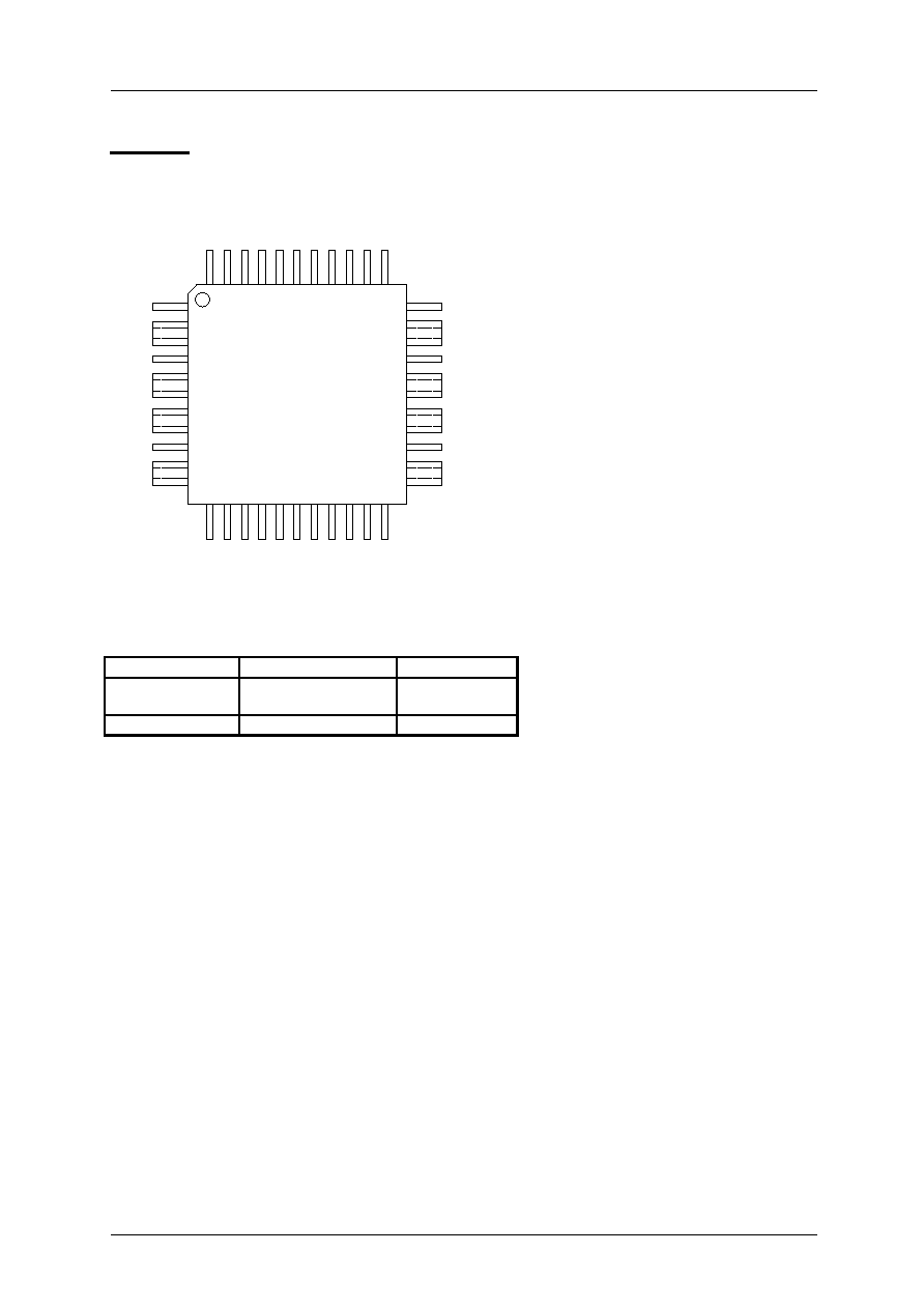
Pinning
Package codes
Package Temperature
range
Code/marking
PQFP 44
industrial
to be announced
TMC246-PI
PQFP 44
automotive *)
TMC246-PA
*) ICs with date code prior to 1304 are not yet tested according to automotive standards, but are
usable within the complete temperature range.
1
9
4
12
17
14
15
16
22
18
21
13
19
20
33
25
30
41
44
43
42
39
36
35
40
38
37
34
TMC 246 / 236A
QFP44
BL2
OB1
OB1
OB2
OB2
BRB
VSB
IN
B
AG
N
D
SL
P
IN
A
GN
D
VS
VT
VC
C
-
-
-
ANN
OA1
OA2
OA2
OA1
BRA
VSA
SR
A
GN
D
SD
O
SDI
SC
K
SR
B
CSN
BL
1
OS
C
EN
N
SP
E
2
3
5
6
7
8
10
11
24
23
27
26
29
28
32
31

TMC246 DATA SHEET (V1.0 / Sep. 4th, 2003)
4
Copyright © 2003, TRINAMIC Microchips GmbH
PQFP44 Dimensions
REF MIN. MAX.
A 12
C 10
D 1
E -
1.6
F 0.09
0.2
G 0.05
0.15
H 0.30
0.45
I 0.45
0.75
K 0.8
All dimensions are in mm.
I
E
F
C
K
H
D
G
A

TMC246 DATA SHEET (V1.0 / Sep. 4th, 2003)
5
Copyright © 2003, TRINAMIC Microchips GmbH
Application Circuit / Block Diagram
R
S
R
SH
Coil A
+V
M
Coil B
100µF
220nF
N
N
N
N
P
P
P
P
TMC246
VT
VS
4
DAC
4
DAC
INA
INB
VREF
REFSEL
PWM-
CT
RL
ANN
SPE
1
0
0
1
Current C
o
ntrolled
Gat
e
Drivers
Curr
ent C
o
ntrolled
Gat
e
D
r
ivers
SLP
R
SLP
PWM
-
CT
RL
OSC
Con
t
ro
l & D
i
agn
o
sis
Parallel
Co
nt
rol
SPI-
In
terf
ace
REFSEL
GND
AGND
Under-
voltage
Tem-
perature
OSC
VCC
1nF
100nF
+V
CC
SCK
SDI
SDO
CSN
ENN
BL2
BL1
[MDBN]
[PHA]
[ERR]
[PHB]
stand alone mode
[MDAN]
OA1
OA2
OB1
OB2
VSB
VSA
SRA
BRA
R
S
SRB
BRB
[...]: function in stand alone mode
Lo
ad
mesu
re-
men
t
VCC/2
Pin Functions
Pin Function
Pin Function
VS
Motor supply voltage
VT
Short to GND detection comparator ≠
connect to VS if not used
VCC
3.0-5.5V supply voltage for analog
and logic circuits
GND
Digital / Power ground
AGND
Analog ground (Reference for SRA,
SRB, OSC, SLP, INA, INB)
OSC
Oscillator capacitor or external clock
input for chopper
INA
Analog current control phase A
INB
Analog current control input phase B
SCK
Clock input of serial interface
SDO
Data output of serial interface (tri-
state)
SDI
Data input of serial interface
CSN
Chip select input of serial interface
ENN
Device enable (low active), and
overvoltage shutdown input
SPE
Enable SPI mode (high active). Tie to
GND for non-SPI applications
ANN
Enable analog current control via
INA and INB (low active)
SLP
Slope control resistor. Tie to GND for
fastest slope
BL1, BL2
Digital blank time select
SRA, SRB Bridge A/B current sense resistor input
OA1, OA2 Output of full-bridge A
OB1, OB2 Output of full-bridge B
VSA, VSB Supply voltage for bridge A/B
BRA, BRB Bridge A/B sense resistor