 | –≠–ª–µ–∫—Ç—Ä–æ–Ω–Ω—ã–π –∫–æ–º–ø–æ–Ω–µ–Ω—Ç: 855833 | –°–∫–∞—á–∞—Ç—å:  PDF PDF  ZIP ZIP |
Data Sheet
Part Number 855833
1880 MHz SAW Split Band Filter
Subject to change or obsolescence without notice
Last Updated: 14-May-2001
Page 1 of 7
Features
∑
For PCS applications
∑
Usable bandwidth 30 MHz (each band)
∑
Low
loss
∑
No impedance matching required for operation
at 50
∑
Single-ended
operation
∑
Ceramic Surface Mount Package (SMP)
∑
Small
size
∑
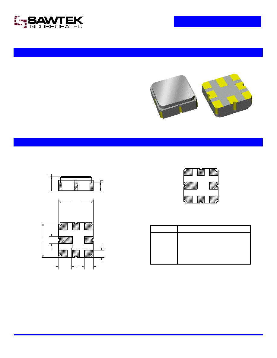
Package
Pin Configuration
Surface Mount 3.0 x 3.0 x 1.22 mm
8
7
6
5
4
3
2
1
1.20
0.75
0.60
3.00
0.69
0.60
3.00
1.22 NOM.
1.32 MAX.
Dimensions shown are nominal in millimeters
All tolerances are
±
0.15mm except overall
length and width
±
0.10mm
Body: Al
2
O
3
ceramic
Lid: Kovar, Ni plated
Terminations: Au plating 0.5 - 1.0
µ
m,
over a 2 - 6
µ
m Ni plating
Pad No. Description
1
Input band #1
3
Input band #2
5
Output band #2
7
Output band #1
2,4,6,8
Case ground
Data Sheet
Part Number 855833
1880 MHz SAW Split Band Filter
Subject to change or obsolescence without notice
Last Updated: 14-May-2001
Page 2 of 7
Band #1 Electrical Specifications
(1)
Operating Temperature Range:
(2)
-40 to +85
o
C
Parameter
(3)
Minimum
Typical
Maximum
Unit
Center Frequency
-
1865
-
MHz
Maximum Insertion Loss
1850 - 1880 MHz
-
2
2.5
dB
Passband Ripple
1850 - 1880 MHz
-
0.4
1.5
dB p-p
Absolute Attenuation
DC - 1770 MHz
1770 - 1800 MHz
1930 - 1960 MHz
1960 - 2040 MHz
2040 - 2100 MHz
2100 - 3000 MHz
25
23
35
25
30
25
28
38
40
33
34
34
-
-
-
-
-
-
dB
dB
dB
dB
dB
dB
Input/Output Return Loss
1850 - 1880 MHz
10
16.5
-
dB
Terminating Source Impedance:
(4)
-
50
-
Terminating Load Impedance:
(4)
-
50
-
Operating Temperature Range
-40
+25
+85
o
C
Notes:
1. All specifications are based on the test circuit shown below
2. In production, devices will be tested at room temperature to a guardbanded specification to ensure electrical compliance over
temperature
3. Electrical margin has been built into the design to account for the variations due to temperature drift and manufacturing tolerances
4. This is the optimum impedance in order to achieve the performance shown
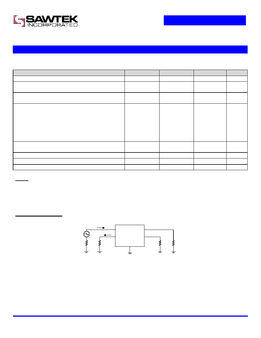
Band #1 Test Circuit:
50
Single-ended
2,4,6,8
1
50
50
50
7
50
5
3
No impedance matching
required
Data Sheet
Part Number 855833
1880 MHz SAW Split Band Filter
Subject to change or obsolescence without notice
Last Updated: 14-May-2001
Page 3 of 7
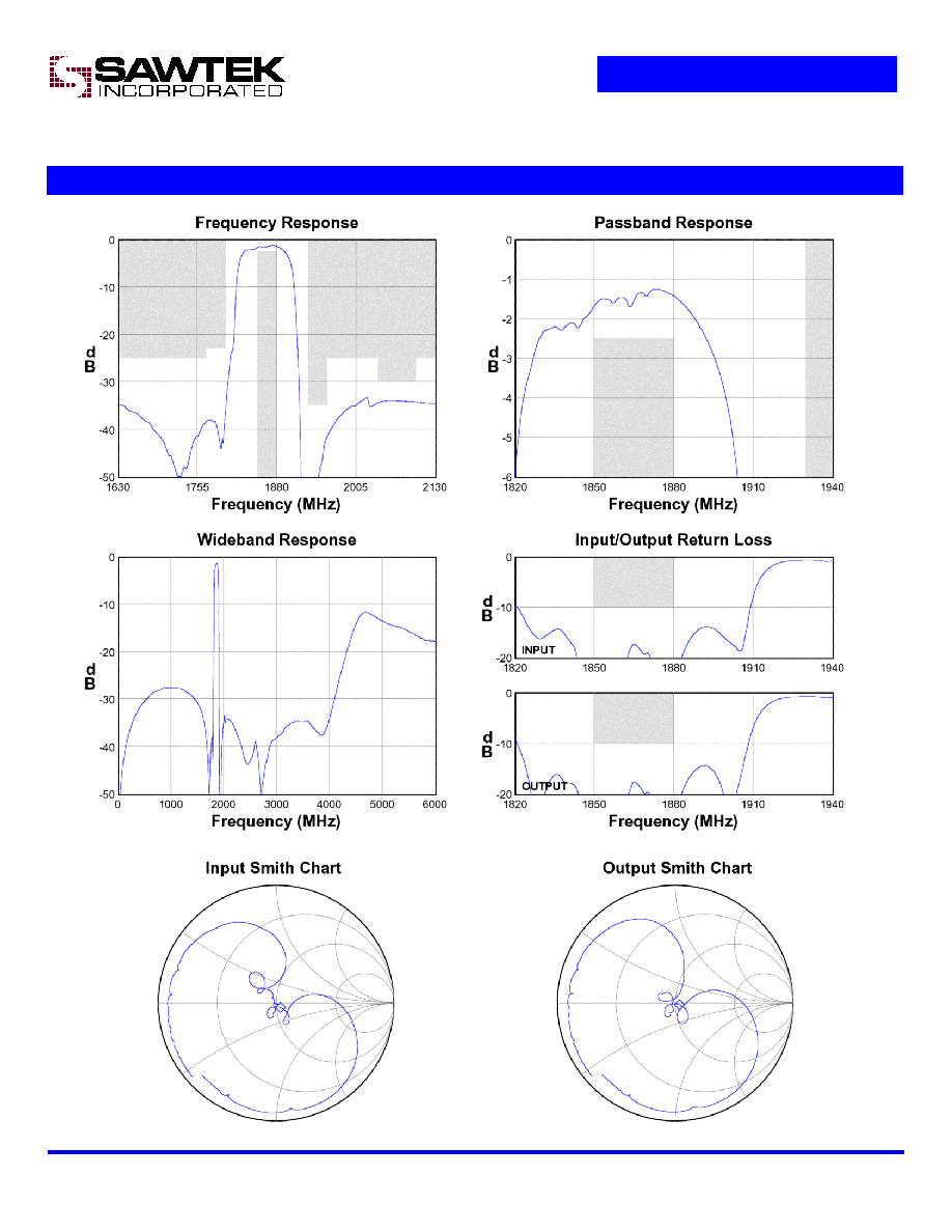
Band #1 Typical Performance
(at +25
o
C)

Data Sheet
Part Number 855833
1880 MHz SAW Split Band Filter
Subject to change or obsolescence without notice
Last Updated: 14-May-2001
Page 4 of 7
Band #2 Electrical Specifications
(1)
Operating Temperature Range:
(2)
-40 to +85
o
C
Parameter
(3)
Minimum
Typical
Maximum
Unit
Center Frequency
-
1895
-
MHz
Maximum Insertion Loss
1880 - 1910 MHz
-
1.9
2.5
dB
Passband Ripple
1880 - 1910 MHz
-
0.4
1.5
dB p-p
Absolute Attenuation
DC - 1800 MHz
1800 - 1830 MHz
1960 - 1990 MHz
1990 - 2040 MHz
2040 - 2100 MHz
2100 - 3000 MHz
25
24
35
25
30
25
28
35
40
34
33
39
-
-
-
-
-
-
dB
dB
dB
dB
dB
dB
Input/Output Return Loss
1880 - 1910 MHz
10
20
-
dB
Terminating Source Impedance:
(4)
-
50
-
Terminating Load Impedance:
(4)
-
50
-
Operating Temperature Range
-40
+25
+85
o
C
Notes:
1. All specifications are based on the test circuit shown below
2. In production, devices will be tested at room temperature to a guardbanded specification to ensure electrical compliance over
temperature
3. Electrical margin has been built into the design to account for the variations due to temperature drift and manufacturing tolerances
4. This is the optimum impedance in order to achieve the performance shown
Band #2 Test Circuit:
50
Single-ended
2,4,6,8
1
50
50
50
7
50
5
3
No impedance matching
required

Data Sheet
Part Number 855833
1880 MHz SAW Split Band Filter
Subject to change or obsolescence without notice
Last Updated: 14-May-2001
Page 5 of 7
Band #2 Typical Performance
(at +25
o
C)