 | –≠–ª–µ–∫—Ç—Ä–æ–Ω–Ω—ã–π –∫–æ–º–ø–æ–Ω–µ–Ω—Ç: 856409 | –°–∫–∞—á–∞—Ç—å:  PDF PDF  ZIP ZIP |
Data Sheet
Part Number 856409
1842.5 MHz SAW Filter
Features
∑ For DCS applications
∑ Usable bandwidth of 75 MHz
∑ Compatible with leading chipset suppliers
∑ Ultra low loss
∑ Single-ended input, 50
∑ Balanced output, 200
∑ Chip Scale Package (CSP)
∑ Hermetic
∑
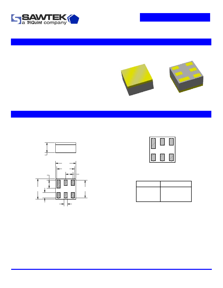
Package
Pin Configuration
Surface Mount 1.50 x 1.50 x 0.76 mm
Bottom View
1
2
3
6
5
4
Pin No.
Description
2
Input
6,4
Output
1,3,5
Case
ground
0.25
0.55
0.40
0.60
1.35
1.50
1.35
1.50
0.76 NOM.
0.84 MAX.
Dimensions shown are nominal in millimeters
All tolerances are
±0.10mm
Body: Al
2
O
3
ceramic
Lid: Kovar or Alloy 42, Au over Ni plated
Terminations: Au plating 0.5 - 1.0
µm,
over a 2 - 6
µm Ni plating
Subject to change or obsolescence without notice
Rev D
08-Dec-2004
Page 1 of 7
Data Sheet
Part Number 856409
1842.5 MHz SAW Filter
Electrical Specifications
(1)
Operating Temperature Range:
(2)
+25
o
C
Parameter
(3)
Minimum
Typical
Maximum
Unit
Center Frequency
- 1842.5 -
MHz
Maximum Insertion Loss
1805
-
1880
MHz
-
1.5
2.0
dB
Absolute Attenuation
100
-
1200
MHz
1200
-
1705
MHz
1705
-
1764
MHz
1764
-
1785
MHz
1920
-
1980
MHz
1980
-
3000
MHz
3000
-
5415
MHz
5415
-
5640
MHz
5640
-
6000
MHz
25
25
20
9
15
20
20
41
38
38
33
25
12
18
26
42
45
42
-
-
-
-
-
-
-
-
-
dB
dB
dB
dB
dB
dB
dB
dB
dB
Output Amplitude Balance (|S
31
/S
21
|)
1805
-
1880
MHz
-1.5
1.3
1.5
dB
Output Phase Balance [(S
31
)-S
21
+180]
1805
-
1880
MHz
-10
2
10
degree
Input/Output VSWR
1805
-
1880
MHz
-
2.0
2.5
Source Impedance
(4)
- 50 -
Load Impedance (Balanced)
(4)
- 200||18nH -
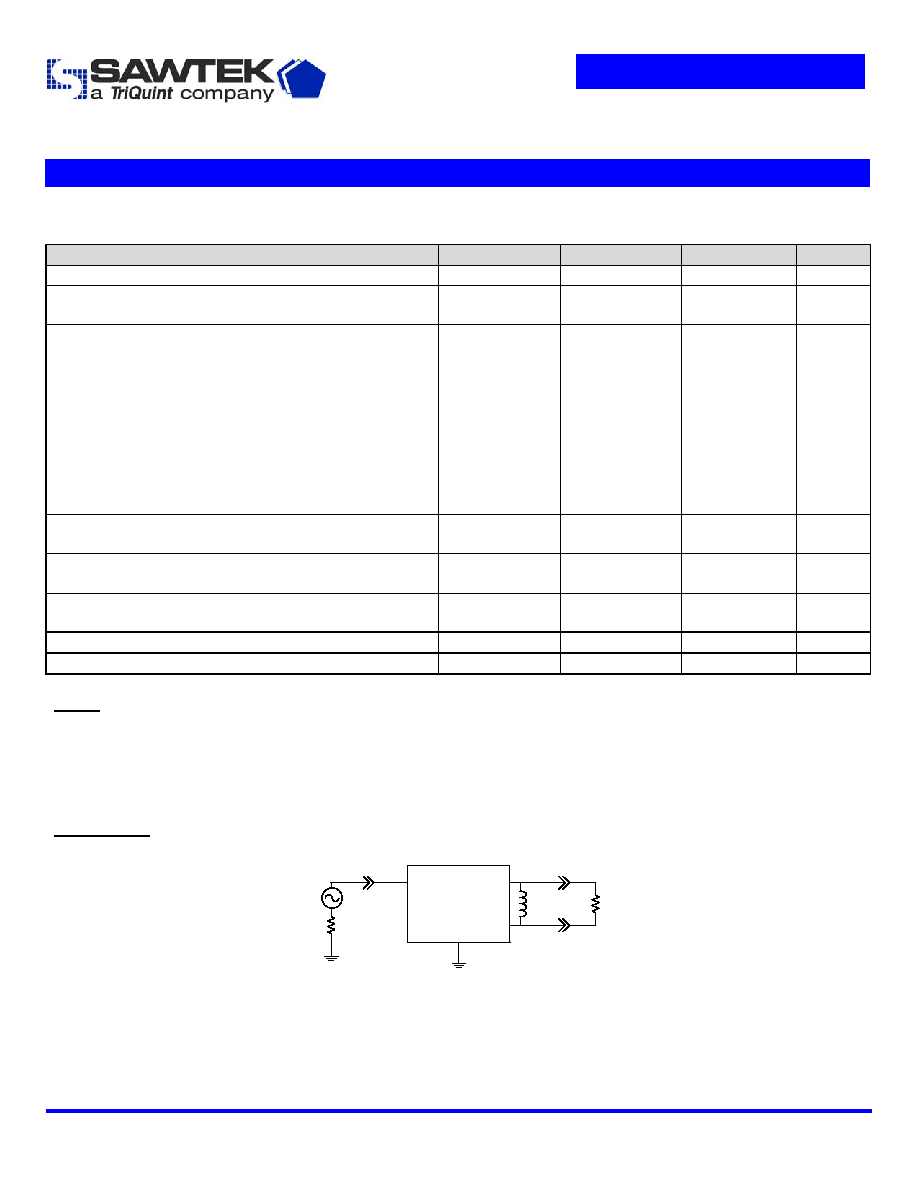
Notes:
1. All specifications are based on the test circuit shown below
2. In production, devices will be tested at room temperature to a guardbanded specification to ensure electrical compliance over
temperature
3. Electrical margin has been built into the design to account for the variations due to temperature drift and manufacturing tolerances
4. This is the optimum impedance in order to achieve the performance shown
Test Circuit:
50
Single-ended
Input
1,3,5
2
4
50
6
200
18nH
200
Balanced
Output
Subject to change or obsolescence without notice
Rev D
08-Dec-2004
Page 2 of 7

Data Sheet
Part Number 856409
1842.5 MHz SAW Filter
Electrical Specifications
(1)
Operating Temperature Range:
(2)
-20 to +75 ∫C
Parameter
(3)
Minimum
Typical
Maximum
Unit
Center Frequency
- 1842.5 -
MHz
Maximum Insertion Loss
1805
-
1880
MHz
-
1.5
2.3
dB
Absolute Attenuation
100
-
1200
MHz
1200
-
1705
MHz
1705
-
1764
MHz
1764
-
1785
MHz
1920
-
1980
MHz
1980
-
3000
MHz
3000
-
5415
MHz
5415
-
5640
MHz
5640
-
6000
MHz
25
25
20
6
15
20
20
41
38
38
33
25
12
18
26
42
45
42
-
-
-
-
-
-
-
-
-
dB
dB
dB
dB
dB
dB
dB
dB
dB
Output Amplitude Balance (|S
31
/S
21
|)
1805
-
1880
MHz
-1.5
1.3
1.5
dB
Output Phase Balance [(S
31
)-S
21
+180]
1805
-
1880
MHz
-10
2
10
degree
Input/Output VSWR
1805
-
1880
MHz
-
2.0
2.6
Source Impedance
(4)
- 50 -
Load Impedance (Balanced)
(4)
- 200||18nH -
Notes:
1. All specifications are based on the test circuit shown below
2. In production, devices will be tested at room temperature to a guardbanded specification to ensure electrical compliance over
temperature
3. Electrical margin has been built into the design to account for the variations due to temperature drift and manufacturing tolerances
4. This is the optimum impedance in order to achieve the performance shown
Test Circuit:
50
Single-ended
Input
1,3,5
2
4
50
6
200
18nH
200
Balanced
Output
Subject to change or obsolescence without notice
Rev D
08-Dec-2004
Page 3 of 7

Data Sheet
Part Number 856409
1842.5 MHz SAW Filter
Electrical Specifications
(1)
Operating Temperature Range:
(2)
-25 to +80 ∫C
Parameter
(3)
Minimum
Typical
Maximum
Unit
Center Frequency
- 1842.5 -
MHz
Maximum Insertion Loss
1805
-
1880
MHz
-
1.5
2.4
dB
Absolute Attenuation
100
-
1200
MHz
1200
-
1705
MHz
1705
-
1764
MHz
1764
-
1785
MHz
1920
-
1980
MHz
1980
-
3000
MHz
3000
-
5415
MHz
5415
-
5640
MHz
5640
-
6000
MHz
25
25
20
6
15
20
20
41
38
38
33
25
12
18
26
42
45
42
-
-
-
-
-
-
-
-
-
dB
dB
dB
dB
dB
dB
dB
dB
dB
Output Amplitude Balance (|S
31
/S
21
|)
1805
-
1880
MHz
-1.5
1.3
1.5
dB
Output Phase Balance [(S
31
)-S
21
+180]
1805
-
1880
MHz
-10
2
10
degree
Input/Output VSWR
1805
-
1880
MHz
-
2.0
2.8
Source Impedance
(4)
- 50 -
Load Impedance (Balanced)
(4)
- 200||18nH -
Notes:
1. All specifications are based on the test circuit shown below
2. In production, devices will be tested at room temperature to a guardbanded specification to ensure electrical compliance over
temperature
3. Electrical margin has been built into the design to account for the variations due to temperature drift and manufacturing tolerances
4. This is the optimum impedance in order to achieve the performance shown
Test Circuit:
50
Single-ended
Input
1,3,5
2
4
50
6
200
18nH
200
Balanced
Output
Subject to change or obsolescence without notice
Rev D
08-Dec-2004
Page 4 of 7
Data Sheet
Part Number 856409
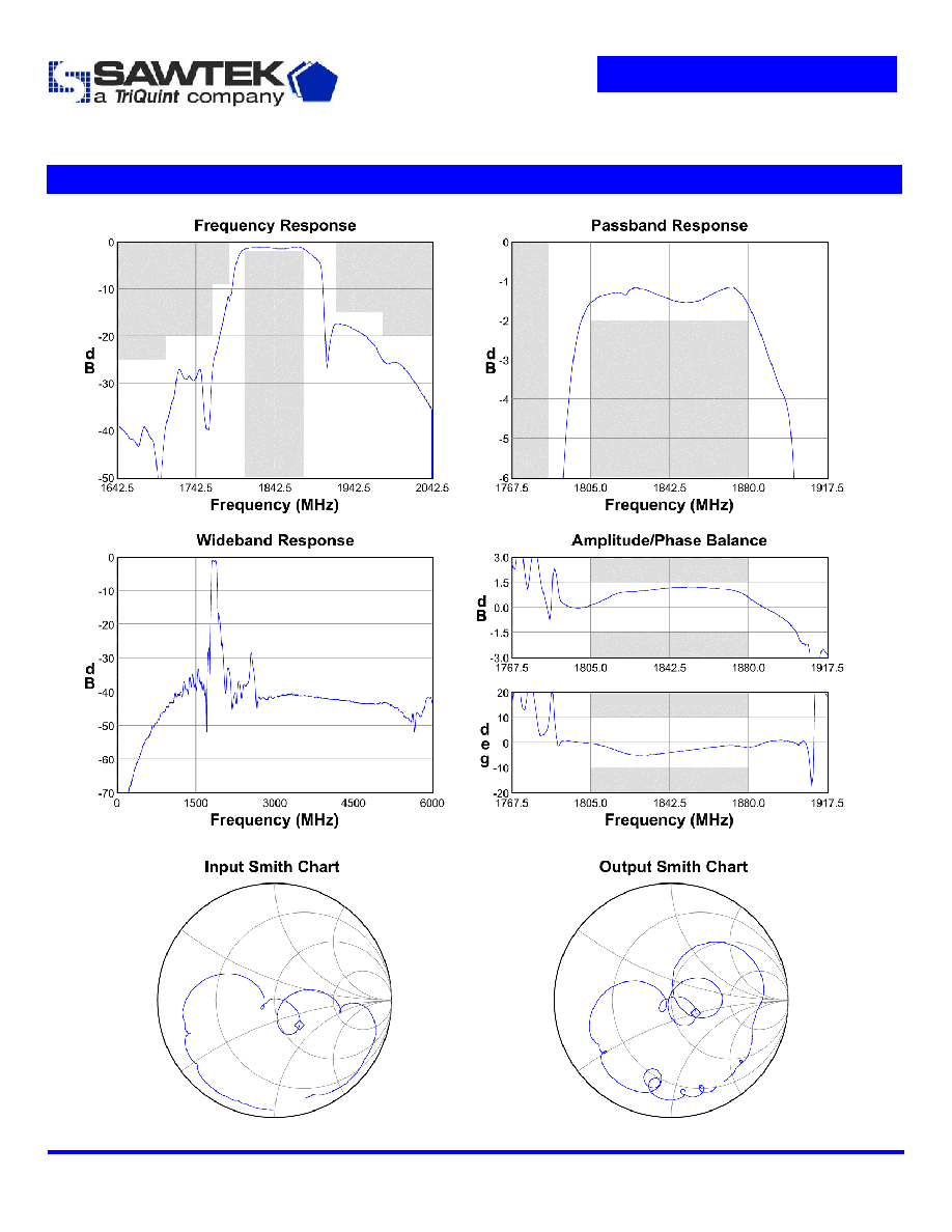
1842.5 MHz SAW Filter
Typical Performance
(at +25
o
C)
Subject to change or obsolescence without notice
Rev D
08-Dec-2004
Page 5 of 7