 | –≠–ª–µ–∫—Ç—Ä–æ–Ω–Ω—ã–π –∫–æ–º–ø–æ–Ω–µ–Ω—Ç: 856441 | –°–∫–∞—á–∞—Ç—å:  PDF PDF  ZIP ZIP |
Data Sheet
Part Number 856441
881.5 MHz SAW Filter
Features
∑ For GSM-850 applications
∑ Usable bandwidth of 25 MHz
∑ Compatible with leading chipset suppliers
∑ Ultra low loss
∑ Single-ended input, 50
∑ Balanced output, 200
∑ Chip Scale Package (CSP)
∑ Hermetic
∑
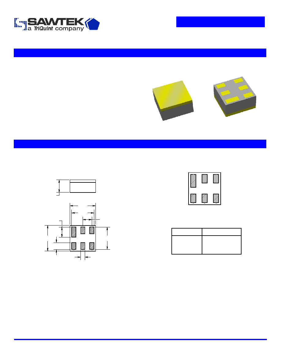
Package
Pin Configuration
Surface Mount 1.50 x 1.50 x 0.76 mm
Bottom View
1
2
3
6
5
4
Pin No.
Description
2
Input
4,6
Output
1,3,5
Case
ground
0.25
0.55
0.40
0.60
1.35
1.50
1.35
1.50
0.76 NOM.
0.84 MAX.
Dimensions shown are nominal in millimeters
All tolerances are
±0.10mm
Body: Al
2
O
3
ceramic
Lid: Kovar or Alloy 42, Au over Ni plated
Terminations: Au plating 0.5 - 1.0
µm,
over a 2 - 6
µm Ni plating
Subject to change or obsolescence without notice
Rev C
08-Dec-2004
Page 1 of 6
Data Sheet
Part Number 856441
881.5 MHz SAW Filter
Electrical Specifications
(1)
Operating Temperature Range:
(2)
+25
o
C
Parameter
(3)
Minimum
Typical
Maximum
Unit
Center Frequency
- 881.5 -
MHz
Maximum Insertion Loss
869
-
894
MHz
-
1.2
1.5
dB
Amplitude Variation
869 - 894 MHz
-
0.4
1.2
dB p-p
Absolute Attenuation
10
-
824
MHz
824
-
842
MHz
842
-
849
MHz
914
-
970
MHz
970
-
2607
MHz
2607
-
2682
MHz
2682
-
4345
MHz
4345
-
4470
MHz
4470
-
6000
MHz
30
30
22
18
22
41
38
37
38
42
35
24
19.5
30
52
40
55
42
-
-
-
-
-
-
-
-
-
dB
dB
dB
dB
dB
dB
dB
dB
dB
Output Amplitude Balance (|S
31
/S
21
|)
869
-
894
MHz
-1
0.7
1
dB
Output Phase Balance [(S
31
)-S
21
+180]
869
-
894
MHz
-10
7
10
degree
Input/Output VSWR
869
-
894
MHz
-
1.7
2.5
Source Impedance
(4)
- 50 -
Load Impedance (Balanced)
(4)
- 200||30nH -
Notes:
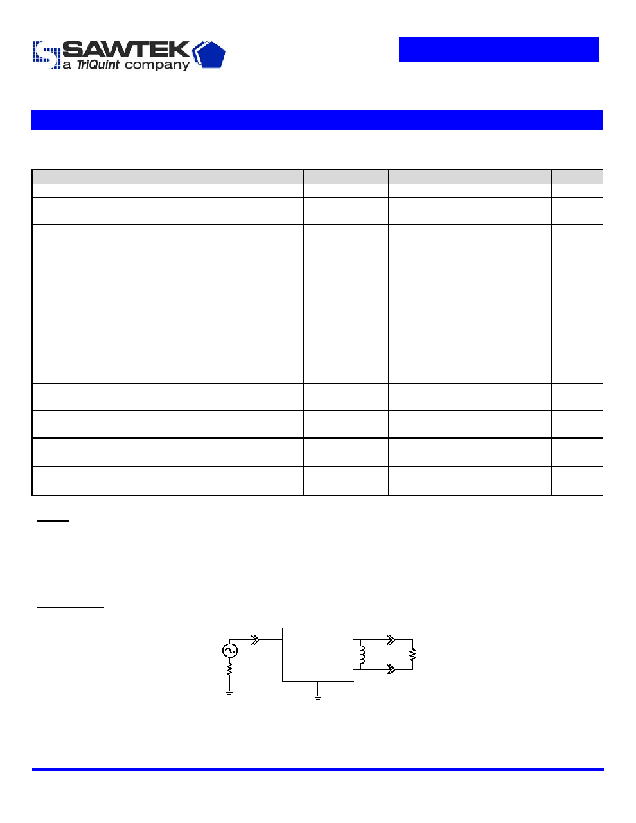
1. All specifications are based on the test circuit shown below
2. In production, devices will be tested at room temperature to a guardbanded specification to ensure electrical compliance over
temperature
3. Electrical margin has been built into the design to account for the variations due to temperature drift and manufacturing tolerances
4. This is the optimum impedance in order to achieve the performance shown
Test Circuit:
50
Single-ended
Input
1,3,5
2
4
50
6
200
30nH
200
Balanced
Output
Subject to change or obsolescence without notice
Rev C
08-Dec-2004
Page 2 of 6

Data Sheet
Part Number 856441
881.5 MHz SAW Filter
Electrical Specifications
(1)
Operating Temperature Range:
(2)
-25 to +80
o
C
Parameter
(3)
Minimum
Typical
Maximum
Unit
Center Frequency
- 881.5 -
MHz
Maximum Insertion Loss
869
-
894
MHz
-
1.2
1.9
dB
Amplitude Variation
869 - 894 MHz
-
0.4
1.2
dB p-p
Absolute Attenuation
10
-
824
MHz
824
-
842
MHz
842
-
849
MHz
914
-
970
MHz
970
-
2607
MHz
2607
-
2682
MHz
2682
-
4345
MHz
4345
-
4470
MHz
4470
-
6000
MHz
30
30
22
18
22
41
38
37
38
42
35
24
19.5
30
52
40
55
42
-
-
-
-
-
-
-
-
-
dB
dB
dB
dB
dB
dB
dB
dB
dB
Output Amplitude Balance (|S
31
/S
21
|)
869
-
894
MHz
-1
0.7
1
dB
Output Phase Balance [(S
31
)-S
21
+180]
869
-
894
MHz
-10
7
10
degree
Input/Output VSWR
869
-
894
MHz
-
1.7
2.5
Source Impedance
(4)
- 50 -
Load Impedance (Balanced)
(4)
- 200||30nH -
Notes:
1. All specifications are based on the test circuit shown below
2. In production, devices will be tested at room temperature to a guardbanded specification to ensure electrical compliance over
temperature
3. Electrical margin has been built into the design to account for the variations due to temperature drift and manufacturing tolerances
4. This is the optimum impedance in order to achieve the performance shown
Test Circuit:
50
Single-ended
Input
1,3,5
2
4
50
6
200
30nH
200
Balanced
Output
Subject to change or obsolescence without notice
Rev C
08-Dec-2004
Page 3 of 6
Data Sheet
Part Number 856441
881.5 MHz SAW Filter
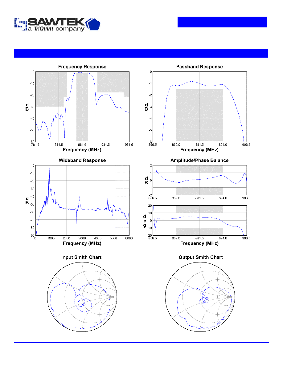
Typical Performance
(at +25
o
C)
Subject to change or obsolescence without notice
Rev C
08-Dec-2004
Page 4 of 6
Data Sheet
Part Number 856441
881.5 MHz SAW Filter
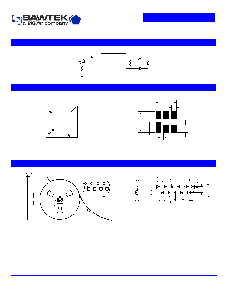
Matching Schematics
50
Single-ended
Input
1,3,5
2
4
50
6
200
30nH
200
Balanced
Output
Marking
PCB Footprint
7
WWY
M
Date code
MFG site
ID dot
Marking
code
0.20
0.70
0.50
0.35
1.45
1.45
The date code consists of: WW = 2 digit week,
Y = last digit of year, M = manufacturing site code
This footprint represents a recommendation only
Dimensions shown are nominal in millimeters
Tape and Reel
A
A
Section A-A
0.25
1.09
1.83
1.83
ÿ1.5
ÿ1.0
4.0
4.0
2.0
8.0
3.5
1.75
8.8
ID dot
2.0
Direction of travel
ÿ330
ÿ20.2
ÿ13.0
ÿ102
2.7
Dimensions shown are nominal in millimeters
Packaging quantity: 10000 units/reel
Subject to change or obsolescence without notice
Rev C
08-Dec-2004
Page 5 of 6