 | –≠–ª–µ–∫—Ç—Ä–æ–Ω–Ω—ã–π –∫–æ–º–ø–æ–Ω–µ–Ω—Ç: E2551H53 | –°–∫–∞—á–∞—Ç—å:  PDF PDF  ZIP ZIP |
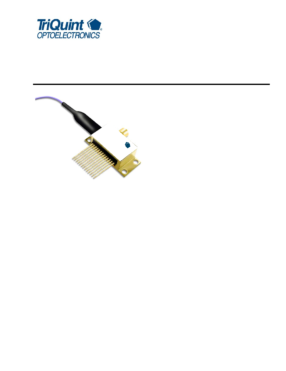
E2551 10 Gb/s EML Modules
for up to 80 km Transmission
Data Sheet
October 2003
Features
Integrated electroabsorption modulator
1.5
µm wavelength, full C-band
Characterized for 10 Gb/s operation
Applicable at 10.66 Gb/s FEC rates
For use up to 80 km (1600 ps/nm)
Low modulation voltage
Temperature stabilized
Integral driver IC
Wavelength selectable to ITU-T standards
Ultrastable wavelength aging for DWDM
Replacement for E2581
Applications
SONET/SDH applications
Ultrahigh capacity WDM system applications
High-speed data communication
Digitized video
Description
The E2551 EML, with integral driver IC, is designed for
10 Gb/s DWDM or TDM transmission applications. It
integrates a CW laser with an electroabsorption modu-
lator (EML) in the same semiconductor chip. This
device can replace external modulators that are often
bulkier, more expensive, and require more drive elec-
tronics than the EML. The E2551 uses an SMP-type,
subminiature, push-on connector to handle the RF sig-
nal. The package also contains a thermoelectric cooler
(TEC), thermistor, rear-facet monitor photodiode, and
an optical isolator. The E2551 operates over distances
of 80 km.
The nominal input impedance of the E2551 is 50
.
The package is qualified to the Telcordia Technolo-
giesTM TA-TSY-000468 standard.
The E2551 is available in the full range of C-band
ITU-T wavelengths for use in DWDM systems operat-
ing at 10 Gb/s per channel. The device exhibits excel-
lent wavelength stability, supporting operation at
100 GHz channel spacing over 20 years (assuming an
end-of-life aging condition of <±100 pm). Typically,
external wavelength stabilization is not required in sys-
tems of this type, using TriQuint's EML products. The
package also offers excellent stability of wavelength vs.
case temperature, with a maximum coefficient of
±0.5 pm/∞C.
The E2551 is intended as a direct replacement for
TriQuint's E2581 device. It has the same functionality
as the E2581 with improved electroabsorption modula-
tor driver. The main improvement is demonstrated by
the improved stability of the output eye diagram for
varying input signal amplitude.
Æ
riQ
T
uin
t
OP
TO
EL
EC
TR
ON
ICS
E2
551
10 G
b/s
La
ser
M
od
ule
2
For additional information and latest specifications, see our website: www.triquint.com
E2551 10 Gb/s EML Modules
Data Sheet
for up to 80 km Transmission
October 2003
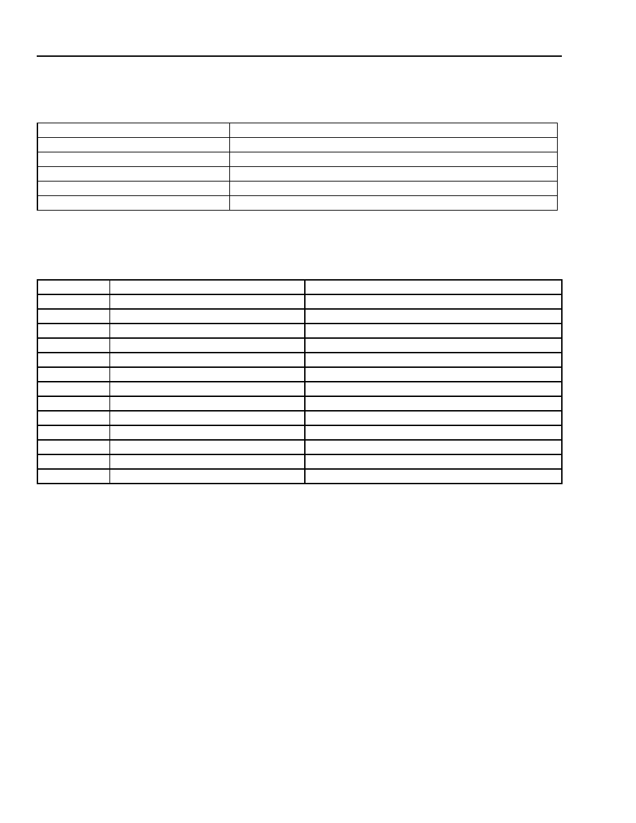
Module Characteristics
Table 1. Module Characteristics
Pin Information
Table 2. Pin Descriptions
Note: For full details of pin functions and required bias levels for the version with the IC, refer to the Application Note, 10 Gb/s EML with Integral
Driver IC: Pin Definitions And Operation (AP03-049).
Parameter
Description
Package Type
13-pin package with SMP-type connector RF input.
Fiber
Standard single-mode fiber.
Fiber Length
33 inches (838.20 mm) minimum.
Optical Connector
Various connectors available on request.
RF Input (SMP-type connector)
Impedance 50
(exterior of RF connector is connected to case).
Pin Number
Pin Name
Description
1
THERM, LASER≠, CASE
Combined thermistor/laser cathode/case.
2
THERM
Thermistor.
3
LASER+
Laser anode.
4
BACK DET≠
Monitor anode (≠).
5
BACK DET+
Monitor cathode (+).
6
V
EA
Modulator offset.
7
NC
No connect/reserved.
8
NC
No connect/reserved.
9
V
OA
Optical amplitude adjust.
10
V
DCA
Duty cycle adjust.
11
V
SS
Voltage supply to the IC.
12
TEC+
Thermoelectric cooler (+)
13
TEC≠
Thermoelectric cooler (≠).
For additional information and latest specifications, see our website: www.triquint.com
3
Data Sheet
E2551 10 Gb/s EML Modules
October 2003
for up to 80 km Transmission
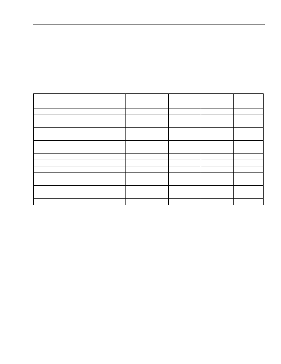
Target Specifications
Absolute Maximum Ratings
Stresses in excess of the absolute maximum ratings can cause permanent damage to the device. These are abso-
lute stress ratings only. Functional operation of the device is not implied at these or any other conditions in excess
of those given in the operational sections of the data sheet. Exposure to absolute maximum ratings for extended
periods can adversely affect device reliability.
Table 3. Absolute Maximum Ratings
For the E2551 EML to function properly, it is very important to keep the voltage supply to the IC (V
SS
) accurate to
within ± 1% of the recommended voltage. This voltage is included on the device's testing data sheet. It is recom-
mended that a voltage regulator be used to maintain this supply voltage at a constant level over time. This voltage
should be measured on the V
SS
pin (pin 11) of the EML.
Parameter
Conditions
Min
Max
Unit
Laser Diode Reverse Voltage
dc
--
2
V
Laser Diode Forward Current
dc
--
150
mA
Optical Output Power
CW
--
10
mW
Modulator Reverse Voltage
--
--
3.5
V
Modulator Forward Voltage
--
--
1
V
Monitor Diode Reverse Voltage
--
--
10
V
Monitor Diode Forward Voltage
--
--
1
V
Storage Temperature Range
--
≠40
85
∞C
Operating Temperature Range
--
≠10
70
∞C
V
DCA
Voltage (pin 10)
--
V
SS
≠ 0.5
V
SS
+ 2.5
V
V
OA
Voltage (pin 9)
--
V
SS
≠ 0.5
V
SS
+ 1.5
V
V
EA
Bias Voltage (pin 6)
--
V
SS
≠ 0.5
V
SS
+ 2.5
V
Supply Voltage for IC Driver V
SS
(pin 11)
--
≠5.5
0
V
Supply Current for IC Driver I
SS
(pin 11)
--
--
300
mA
Package Thermistor Temperature
1
1. To prevent package over-temperature conditions.
--
--
100
∞C
Thermoelectric Cooler in Heating Mode
1
--
--
0.5
A
4
For additional information and latest specifications, see our website: www.triquint.com
E2551 10 Gb/s EML Modules
Data Sheet
for up to 80 km Transmission
October 2003
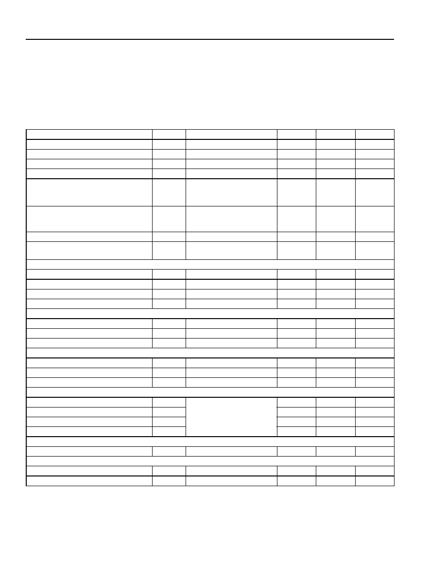
Target Specifications
(continued)
Characteristics
Minimum and maximum values specified over operating case temperature range. Typical values are measured at
room temperature unless otherwise noted.
Table 4. Optical and Electrical Specifications (Chip operating temp. = 15
∞C to 35 ∞C, except where noted.)
1. Modulated operational values are defined to be I = I
OP
, T = T
OP
, at all specified operating conditions, 9.95328 Gb/s modulation, 2
31
≠ 1 PRBS
(operating parameters for 80 km will be provided). Laser diode temperature can be set within a range of 15
∞C to 35 ∞C to take advantage of
wavelength tuning, provided that it will meet all other specifications at this preset temperature. V
M
= modulator voltage.
2. Over 1600 ps/nm, V
EA
, V
DCA
, and V
OA.
3. With fourth-order Bessel-Thomson filter at OC-192.
4. Without filter.
5. T
CASE
= 70
∞C, T
LASERCHIP
= T
OP.
Parameter
Symbol
Conditions
Min
Max
Unit
Threshold Current (BOL)
I
TH
--
5
35
mA
Forward Voltage
V
F
I
F
= I
OP
@ T
OP
--
2.2
V
Operating Current
I
OP
--
50
100
mA
Threshold Power
P
TH
I
F
= I
TH
, V
M
= 0 V
--
80
µW
Fiber Output Power (average):
Beginning of Life
End of Life
P
AVG-BOL
P
AVG-EOL
Note 1
Note 1
≠2.0
≠2.5
--
--
dBm
dBm
Peak Wavelength
(Wavelength can be specified to the
ITU wavelength channels.)
PK
Note 1
1528.7
1563.9
nm
Side-mode Suppression Ratio
SMSR
V
M
= 0 V, I
F
= I
OP
, T
OP
35
--
dB
Dispersion Penalty
BER = 10
≠10
, D = 1600 ps/nm
DP
Notes 1, 2
--
2.0
dB
Modulator/Driver
RF Extinction Ratio
ER
RF
Notes 1, 3
10
--
dB
RF Return Loss (100 MHz to 10 GHz)
S
11
--
≠10
--
dB
Input Voltage (ac coupled)
V
IN
0.5
1.0
V
Rise/Fall Time (20%--80%)
t
R
/t
F
Note 4
--
40
ps
Monitor Diode
Monitor Current
I
BD
V
BD
= 5 V, I
F
= I
OP
40
1100
µA
Dark Current
I
D
V
BD
= 5 V
--
0.1
µA
Capacitance
C
V
BD
= 5 V, F = 1 MHz
--
25
pF
Thermistor
Resistance
R
THERM
T = 25
∞C
9.8
10.2
k
Thermistor Current
I
TC
--
10
100
µA
Thermistor B Constant
B
--
3700
4100
--
Thermoelectric Cooler (TEC)
TEC Current
I
TEC
Note 5
--
1.1
A
TEC Voltage
V
TEC
--
2.6
V
TEC Power
P
TEC
--
2.9
W
TEC Capacity
T
55
--
C
Optical Isolation
Optical Isolation
--
Note 5
30
--
dB
Package
Output Power Stability
T
CASE
= ≠10
∞C to +70 ∞C
≠0.5
0.5
dB
Wavelength vs. Case Temperature
d
/dT
T
CASE
= ≠10
∞C to +70 ∞C
≠0.5
0.5
pm/
∞C
For additional information and latest specifications, see our website: www.triquint.com
5
Data Sheet
E2551 10 Gb/s EML Modules
October 2003
for up to 80 km Transmission
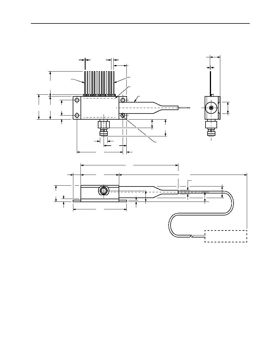
Outline Diagram
0.291
(7.38)
0.215
(5.47)
0.078
(1.98)
0.050
(1.27)
0.020
(0.51)
0.350
(8.89)
0.500
(12.7)
0.551
(13.99)
0.500
(12.7)
LEAD 13
LEAD 1
TRADEMARK CODE, LASER SERIAL NUMBER
AND DATE CODE LABEL IN AREA SHOWN
BEND LIMITER
0.498
(12.64)
1.025
(26.04)
0.106
(2.7)
0.190
(4.82)
12 PLACES
CONNECTOR TYPE
AS SPECIFIED
1.180
(29.97)
2.024
(51.41)
0.820
(20.83)
33.0
0.56
(1.42)
0.365
(9.27)
0.180
(4.56)
0.030
(0.75)
0.228
(5.78)
0.98
(2.5)
0.260
(6.6)
0.200
(5.08)
0.010
± 0.002
(0.25
± 0.064)
3 PLACES
0.215
(5.45)
(838.20)
MIN
4 PLACES
0.355
(9.00)
0.154
(3.91)
MIN.
0.075
(1.9)