 | –≠–ª–µ–∫—Ç—Ä–æ–Ω–Ω—ã–π –∫–æ–º–ø–æ–Ω–µ–Ω—Ç: E2560H35 | –°–∫–∞—á–∞—Ç—å:  PDF PDF  ZIP ZIP |
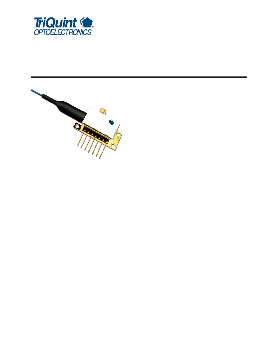
E2560-Type 10 Gb/s EML Modules
for 2 km--40 km Transmission
Data Sheet
October 2003
Features
Integrated electroabsorptive modulator
1.5
µm wavelength
Characterized for 10 Gb/s operation
For use up to 40 km at 10 Gb/s
Low modulation voltage
Temperature stabilized
Wavelength selectable to ITU-T standards
Ultrastable wavelength aging for DWDM
Applications
SONET/SDH
Ultrahigh capacity WDM systems
High-speed data communications
Digitized video
Description
The E2560-type EML (without integral driver IC) is
designed for 10 Gb/s DWDM or TDM transmission
applications. They integrate a CW laser with an elec-
troabsorptive modulator in the same semiconductor
chip and are an extension of TriQuint's existing E2500-
series of devices. These devices can replace external
modulators that are often bulkier, more expensive, and
require more drive electronics than the EML. They
incorporate a small-profile GPO
TM connector to handle
the RF signal. The package also contains a thermo-
electric cooler, thermistor, rear-facet monitor photo-
diode, and an optical isolator.
The E2560-type is available for transmission distances
of up to 20 km or 40 km.
The nominal input impedance of the E2560 version is
50
. The package is qualified to the Telcordia
Technologies
TM TA-TSY-000468 standard.
The short-haul (2 km--20 km) version of the
E2560-type (E2566) is offered as a single-channel
device operating within a wavelength range of
1530 nm--1563 nm. For 40 km, E2560 is available in a
range of ITU-T wavelengths for use in DWDM systems
operating at 10 Gb/s per channel.
The devices exhibit excellent wavelength stability, sup-
porting operation at 100 GHz channel spacing over
20 years (assuming an end-of-life aging condition of
<
±100 pm). Typically, no external wavelength stabiliza-
tion is required in systems of this type, using the
TriQuint E2560 EMLs. The package also offers excel-
lent stability of wavelength vs. case temperature, with
a maximum coefficient of ±0.5 pm/
∞C.
Æ
riQ
T
uint
OPT
OEL
CTR
ONIC
S
10 G
b/s L
aser
Mod
ule
E256
0
2
For additional information and latest specifications, see our website: www.triquint.com
E2560-Type 10 Gb/s EML Modules
Data Sheet
for 2 km--40 km Transmission
October 2003
Module Characteristics
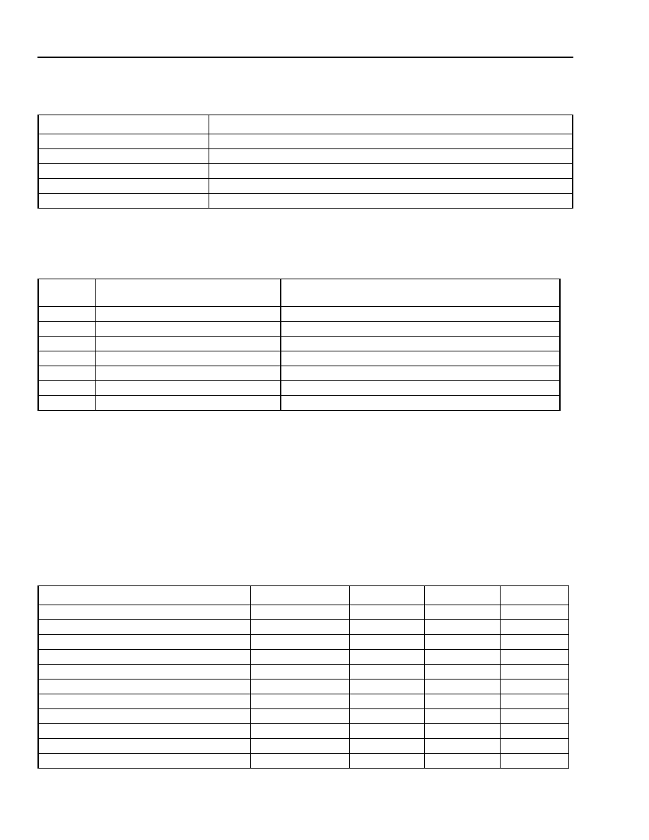
Table 1. Module Characteristics
Pin Information
Table 2. Pin Descriptions
* Laser cathode and modulator ground are connected to case.
Target Specifications
Absolute Maximum Ratings
Stresses in excess of the absolute maximum ratings can cause permanent damage to the device. These are abso-
lute stress ratings only. Functional operation of the device is not implied at these or any other conditions in excess
of those given in the operational sections of the data sheet. Exposure to absolute maximum ratings for extended
periods can adversely affect device reliability.
Table 3.
Absolute Maximum Ratings
Parameter
Description
Package Type
7-pin package with GPO connector RF input.
Fiber
Standard single-mode fiber.
Optical Connector
Various connectors available on request.
RF Input (SMP-type connector)
Impedance 50
(exterior of RF connector is connected to case).
Bit Rate
Up to12.5 Gb/s.
Pin
Number
Pin Name
Description
1
THERM, LASER-, CASE
Combined Thermistor/Laser Cathode/Case.
2
THERM
Thermistor.
3
LASER+
Laser anode*.
4
BACK DET≠
Monitor anode (≠).
5
BACK DET+
Monitor cathode (+).
6
TEC+
Thermoelectric cooler (+).
7
TEC≠
Thermoelectric cooler (≠).
Parameter
Conditions
Min
Max
Unit
Laser Diode Reverse Voltage
CW
--
2
V
Laser Diode Forward Current
CW
--
150
mA
Optical Output Power
CW
--
10
mW
Modulator Reverse Voltage
--
--
5
V
Modulator Forward Voltage
--
--
1
V
Monitor Diode Reverse Voltage
--
--
10
V
Monitor Diode Forward Voltage
--
--
1
V
Storage Temperature
--
--
≠40 to +85
∞C
Operating Temperature
--
--
≠10 to +70
∞C
Thermistor Temperature
1
1. To prevent package over-temperature conditions.
--
--
100
∞C
Thermoelectric Cooler in Heating Mode
1
--
--
0.5
A

For additional information and latest specifications, see our website: www.triquint.com
3
Data Sheet
E2560-Type 10 Gb/s EML Modules
October 2003
for 2 km--40 km Transmission
Target Specifications
(continued)
Characteristics
Minimum and maximum values specified over operating case temperature range. Typical values are measured at
room temperature (25
∞C) unless otherwise noted
Table 4. Optical and Electrical Specifications (Chip operating temp. = 15
∞C to 35 ∞C, except where noted.)
Parameter
Symbol
Conditions
Min
Max
Unit
Threshold Current (BOL)
I
TH
--
5
35
mA
Forward Voltage
V
F
I
F
= I
OP
@ T
OP
--
2.2
V
Operating Current
I
OP
--
50
100
mA
Threshold Power
P
TH
I
F
~ I
TH,
V
M1
= 0V
--
80
µW
Fiber Output Power (Average)
P
AVG
Note 2
≠2
--
dBm
Peak Wavelength
(Wavelength can be specified to the ITU
wavelength channels. See Table 5.)
PK
V
M
= V
ON
T
LASER CHIP
= T
OP
I
F
=
I
OP
1530
1563
nm
Side-mode Suppression Ratio
SMSR
V
M
= 0 V
I
F
=
I
OP,
T
OP
35
--
dB
Dispersion Penalty, BER = 10
≠10
D = 400 ps/nm (E2566 version)
D = 800 ps/nm (E2560, version)
DP
Note 2, 3
--
--
2.0
2.0
dB
dB
Modulator
Peak to Peak Modulator Voltage
V
PP
1.5
2.5
V
On-State Modulator Voltage
V
ON
≠1.0
0
V
Extinction Ratio:
E2560, 40 km version
E2566, 20 km version
ER
RF
Note 2, 4
10
9
--
--
dB
dB
RF Return Loss (0 GHz to 6 GHz)
S
11
V
M
= ≠1 V,
I
F
= I
OP
10
--
dB
RF Return Loss (6 GHz to 8 GHz)
S
11
V
M
= ≠1 V,
I
F
= I
OP
7
--
dB
RF Return Loss (8 GHz to 10 GHz)
S
11
V
M
= ≠1 V,
I
F
= I
OP
5
--
dB
≠3 dB Bandwidth (E2560-series)
BW
V
M
= ≠1 V,
I
F
= I
OP
10
--
GHz
Rise/Fall Time(20%--80%)
t
R
/t
F
Note 4
--
40
ps
Monitor Diode
Monitor Current
I
BD
V
BD
= 5, V,
I
F
=
I
OP
40
1100
µA
Dark Current
I
D
V
BD
= 5 V
--
0.1
µA
Capacitance
C
V
BD
= 5 V, F = 1 MHz
--
25
pF
Thermistor
Resistance
R
THERM
T = 25
∞C
9.5
10.5
k
Thermistor Current
I
TC
--
10
100
µA
Thermistor B Constant
B
--
3700
4100
--
1. V
M
= modulator voltage (dc).
2. Modulated operational values are defined as I = I
OP
, T = T
OP
, at all specified operating conditions, 9.95328 Gb/s modulation, 2
31
≠ 1 PRBS
(operating parameters: I
OP
, T
OP
, V
ON
for E2560 will be provided). Laser diode temperature can be set within a range of 15
∞C to 35 ∞C to take
advantage of wavelength tuning, provided that it will meet all other specs at this preset temperature.
3. 800 ps/nm (40 km) for E2560 and 400 ps/nm (20 km) for E2566
.
4. Without filter, O/E bandwidth > 20 GHz.
4
For additional information and latest specifications, see our website: www.triquint.com
E2560-Type 10 Gb/s EML Modules
Data Sheet
for 2 km--40 km Transmission
October 2003
1. V
M
= modulator voltage (dc).
2. Modulated operational values are defined as I = I
OP
, T = T
OP
, at all specified operating conditions, 9.95328 Gb/s modulation, 2
31
≠ 1 PRBS
(operating parameters: I
OP
, T
OP
, V
ON
for E2560 will be provided). Laser diode temperature can be set within a range of 15
∞C to 35 ∞C to take
advantage of wavelength tuning, provided that it will meet all other specs at this preset temperature.
3. 800 ps/nm (40 km) for E2560 and 400 ps/nm (20 km) for E2566
.
4. Without filter, O/E bandwidth > 20 GHz.
5. T
CASE
= 70
∞C, T
OP
(
LASERCHIP)
= 15
∞C to 35 ∞C.
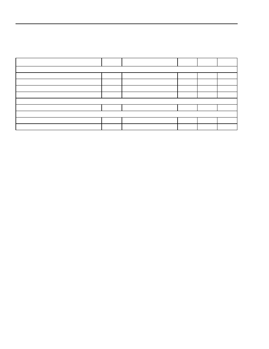
Thermoelectric Cooler
TEC Current
I
TEC
Note 5
--
1.1
A
TEC Voltage
V
TEC
Note 5
--
2.6
V
TEC Power
P
TEC
Note 5
--
2.9
W
TEC Capacity
T
Note 5
--
55
C
Optical Isolation
Optical Isolation
--
Note 5
30
--
dB
Package
Output Power Stability
T
CASE
= ≠10
∞C to +70 ∞C
≠0.5
0.5
dB
Wavelength vs. Case Temperature
d
/ dT
T
CASE
= ≠10
∞C to +70 ∞C
≠0.5
0.5
pm/
∞C
Parameter
Symbol
Conditions
Min
Max
Unit
Target Specifications
(continued)
Table 4. Optical and Electrical Specifications (Chip operating temp. = 15
∞C to 35 ∞C, except where noted.)
(continued)
For additional information and latest specifications, see our website: www.triquint.com
5
Data Sheet
E2560-Type 10 Gb/s EML Modules
October 2003
for 2 km--40 km Transmission
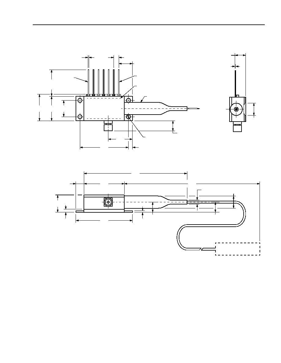
Outline Diagram
0.215
(5.47)
0.291
(7.384)
0.100
(2.54)
0.020
(0.508)
0.350
(8.89)
0.500
(12.7)
0.551
(13.99)
0.50
(12.7)
LEAD 7
LEAD 1
TRADEMARK CODE LASER SERIAL NUMBER
AND DATE CODE LABEL IN AREA SHOWN
BEND LIMITER
0.498
(12.64)
1.025
(26.04)
0.106
(2.7)
0.190
(4.822)
CONNECTOR TYPE
AS SPECIFIED
1.180
(29.97)
2.032
(51.61)
0.820
(20.83)
0.56
(1.42)
0.365
(9.27)
0.180
(4.56)
0.030
(0.75)
0.228
(5.78)
0.98
(2.5)
0.260
(6.6)
0.078
(1.98)
MIN
PLACES
33.0
MIN
(838.20)
0.200
(5.08)
0.010
± 0.002
(0.25
± 0.064)
0.215
(5.45)