 | –≠–ª–µ–∫—Ç—Ä–æ–Ω–Ω—ã–π –∫–æ–º–ø–æ–Ω–µ–Ω—Ç: E2561A59 | –°–∫–∞—á–∞—Ç—å:  PDF PDF  ZIP ZIP |
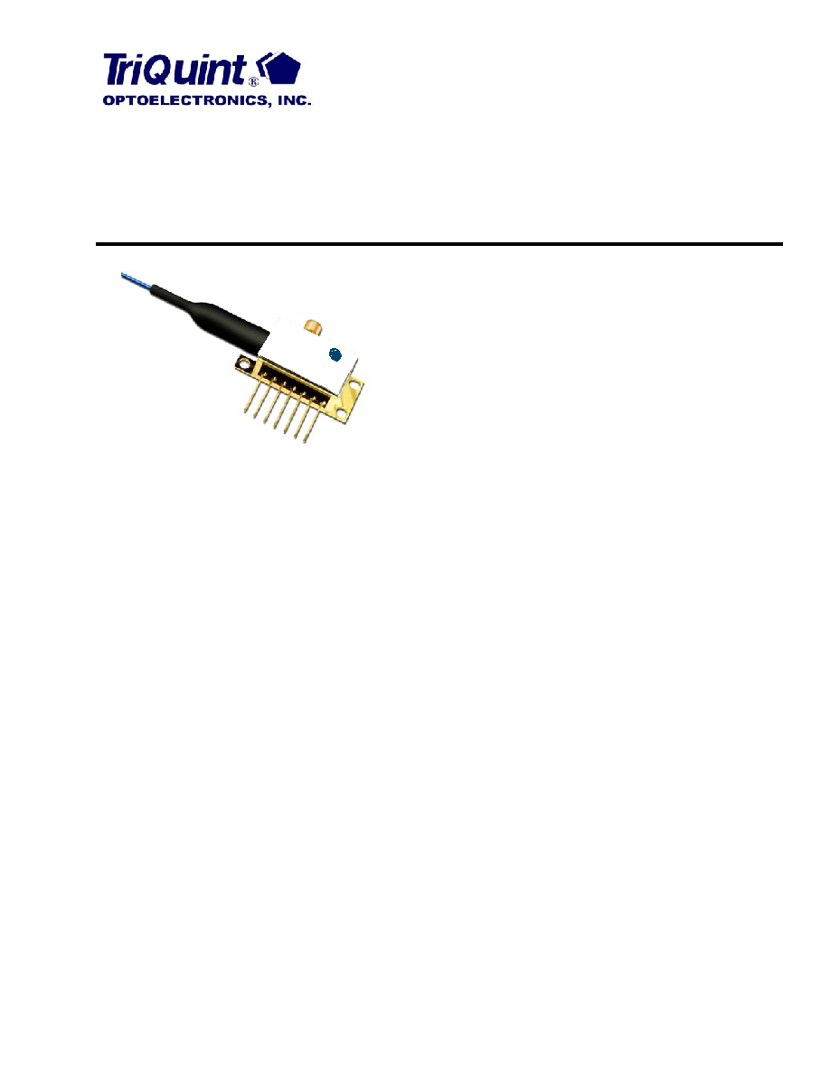
E2561-Series 10 Gb/s EML Modules
for up to 80 km Transmission
Data Sheet
March 2003
Features
Integrated electroabsorption modulator
1.5
µm wavelength, full C-band
Characterized for 10 Gb/s operation
For use up to 80 km at 10 Gb/s
Low modulation voltage
Temperature stabilized
Wavelength selectable to ITU-T standards
Ultrastable wavelength aging for DWDM
Applications
SONET/SDH applications
Ultrahigh capacity WDM system application
High-speed data communication
Digitized video
Description
The E2561-series EMLs are designed for 10 Gb/s
DWDM or TDM transmission applications. The EML
integrates a CW laser with an electroabsorption modu-
lator in the same semiconductor chip. These devices
can replace external modulators that are often bulkier,
more expensive, and require more drive electronics
than the EML. The 10 Gb/s EML uses an SMP-type,
subminiature, push-on connector to handle the RF sig-
nal. The package also contains a thermoelectric cooler
(TEC), thermistor, rear-facet monitor photodiode, and
an optical isolator.
The nominal input impedance of the 10 Gb/s EML is
50
. The package is qualified to the Telcordia Tech-
nologies
TM TA-TSY-000468 standard.
The EML is available in the full range of C-band
ITU-T wavelengths for use in DWDM systems operat-
ing at 10 Gb/s per channel. The device exhibits excel-
lent wavelength stability, supporting operation at
100 GHz channel spacing over 20 years (assuming an
end-of-life aging condition of <±100 pm). Typically,
external wavelength stabilization is not required in sys-
tems of this type, using TriQuint's EML products. The
package also offers excellent stability of wavelength vs.
case temperature, with a maximum coefficient of
±0.5 pm/∞C.
Æ
riQ
T
uint
OPT
OEL
CTR
ONIC
S, IN
C.
10 G
b/s L
aser
Mod
ule
2561
2
For additional information and latest specifications, see our website: www.triquint.com
E2561-Series 10 Gb/s EML Modules
Data Sheet
for up to 80 km Transmission
March 2003
Module Characteristics
Table 1. Module Characteristics
Pin Information
Table 2. Pin Descriptions
Target Specifications
Absolute Maximum Ratings
Stresses in excess of the absolute maximum ratings can cause permanent damage to the device. These are abso-
lute stress ratings only. Functional operation of the device is not implied at these or any other conditions in excess
of those given in the operational sections of the data sheet. Exposure to absolute maximum ratings for extended
periods can adversely affect device reliability.
Table 3. Absolute Maximum Ratings
Parameter
Description
Package Type
E2561: 7-pin package with SMP-type connector RF input.
Fiber
Standard single-mode fiber.
Fiber Length
32.7 inches minimum.
Connector
See Table 6 (additional connector types available on request).
RF Input
Impedance 50
.
Pin Number
Pin Name
Description
1
THERM, LASER≠, CASE
Combined thermistor/laser cathode/case
2
THERM
Thermistor
3
LASER+
Laser anode
4
BACK DET≠
Monitor anode (≠)
5
BACK DET+
Monitor cathode (+)
6
TEC+
Thermoelectric cooler (+)
7
TEC≠
Thermoelectric cooler (≠)
Parameter
Conditions
Min
Max
Unit
Laser Diode Reverse Voltage
CW
--
2
V
Laser Diode Forward Current
CW
--
150
mA
Optical Output Power
CW
--
10
mW
Modulator Reverse Voltage
--
--
3.5
V
Modulator Forward Voltage
--
--
1
V
Monitor Diode Reverse Voltage
--
--
10
V
Monitor Diode Forward Voltage
--
--
1
V
Storage Temperature Range
--
≠40
85
∞C
Operating Temperature Range
--
≠5
70
∞C
For additional information and latest specifications, see our website: www.triquint.com
3
Data Sheet
E2561-Series 10 Gb/s EML Modules
March 2003
for up to 80 km Transmission
Target Specifications
(continued)
Characteristics
Minimum and maximum values specified over operating case temperature range. Typical values are measured at
room temperature unless otherwise noted.
Table 4. Optical and Electrical Specifications (Chip operating temp. = 15
∞C to 35 ∞C, except where noted.)
1. Modulated for 80 km
(1600ps/nm) operation. Modulated operational values are defined to be I = I
OP
, T = T
OP
, at all specified operating
conditions, 9.95328 Gb/s modulation, 2
31
≠ 1 PRBS (operating parameters for 80 km will be provided). Laser diode temperature can be set
in a 15
∞C to 35 ∞C range to take advantage of wavelength tuning, provided that it will meet all other specs at this preset temperature.
V
M
= modulator voltage.
2. Over 1600 ps/nm (80 km)
.
3. T
CASE
= 70
∞C, T
LASERCHIP
= 15
∞C to 35 ∞C.
4. With fourth-order Bessel-Thomson filter.
5. Without filter.
Parameter
Symbol
Conditions
Min
Max
Unit
Threshold Current (BOL)
I
TH
--
5
35
mA
Forward Voltage
V
F
I
F
= I
OP
@ T
OP
--
2.2
V
Operating Current
I
OP
--
50
100
mA
Threshold Power
P
TH
I
F
= I
TH
V
M
= 0 V
--
80
µW
Fiber Output Power (average)
P
AVG
Note 1
≠2
--
dBm
Peak Wavelength
(Wavelength can be specified to
the ITU-T wavelength channels.)
PK
Note 1
1528.7
1563.9
nm
Side-mode Suppression Ratio
SMSR
V
M
= 0 V, I
F
= I
OP
, T
OP
35
--
dB
Modulator Voltage
V
PP
--
1.5
2.5
V
Onstate Voltage
V
ON
--
≠1.0
0
V
Modulator/Driver
RF Extinction Ratio
ER
RF
Notes 1, 4
10
--
dB
RF Return Loss
(130 MHz to 10 GHz)
S
11
V
M
= ≠1 V, I
F
= I
OP
-10
dB
≠3 dB Bandwidth
BW
V
M
= ≠1 V, I
F
= I
OP
11
--
GHz
Rise/Fall Time (20%--80%)
t
R
/t
F
Note 5
--
30
ps
Dispersion Penalty
DP
1600 ps/nm, BER = 10
≠10
Notes 1, 2
--
2.0
dB
Monitor Diode
Monitor Current
I
BD
V
BD
= 5 V, I
F
= I
OP
40
1100
µA
Dark Current
I
D
V
BD
= 5 V
--
0.1
µA
Capacitance
C
V
BD
= 5 V, F = 1 MHz
--
25
pF
Thermistor
Resistance
R
THERM
T = 25
∞C
9.8
10.2
k
Thermistor Current
I
TC
--
10
100
µA
Thermistor B Constant
B
--
3700
4100
--
Thermoelectric Cooler (TEC)
TEC Current
I
TEC
Note 3
--
1.1
A
TEC Voltage
V
TEC
--
2.6
V
TEC Power
P
TEC
--
2.9
W
TEC Capacity
T
55
--
C
Optical Isolation
Optical Isolation
--
Note 3
30
--
dB
Package
Wavelength vs. Case Temperature
d
/dT
T
CASE
= ≠10
∞C to +70 ∞C
≠0.5
0.5
pm/
∞C
4
For additional information and latest specifications, see our website: www.triquint.com
E2561-Series 10 Gb/s EML Modules
Data Sheet
for up to 80 km Transmission
March 2003
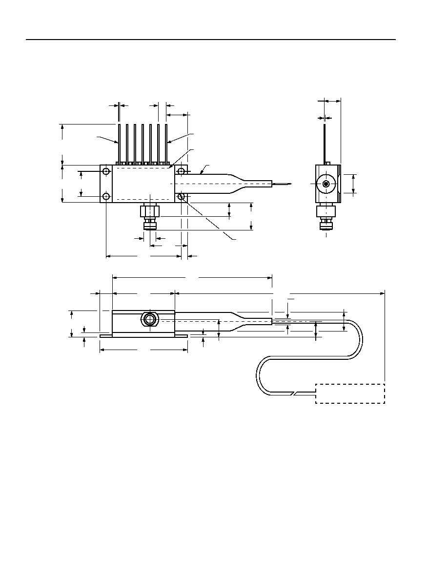
Outline Diagram
Dimensions are in inches and (millimeters).
0.291
(7.38)
0.215
(5.47)
0.078
(1.98)
0.100
(2.54)
0.020
(0.51)
0.350
(8.89)
0.500
(12.7)
0.500
(12.7)
LEAD 7
LEAD 1
TRADEMARK, CODE, LASER SERIAL NUMBER
AND DATE CODE LABEL IN AREA SHOWN
BEND LIMITER
0.498
(12.64)
1.025
(26.04)
0.106
(2.7)
0.190
(4.82)
CONNECTOR TYPE
AS SPECIFIED
1.180
(29.97)
2.03
(51.60)
0.820
(20.83)
0.56
(1.42)
0.365
(9.27)
0.180
(4.56)
0.030
(0.75)
0.228
(5.78)
0.98
(2.5)
0.260
(6.6)
0.200
(5.08)
0.010
± 0.002
(0.25
± 0.064)
0.215
(5.46)
32.7
4 PLACES
0.330
(8.37)
0.164
(4.17)
MIN.
(830.6)
MIN.
For additional information and latest specifications, see our website: www.triquint.com
5
Data Sheet
E2561-Series 10 Gb/s EML Modules
March 2003
for up to 80 km Transmission
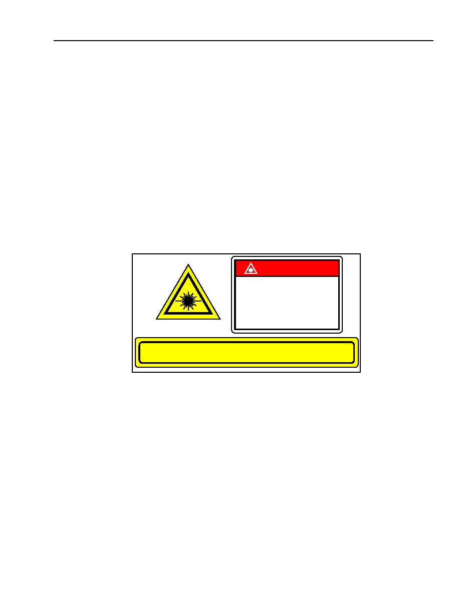
Laser Safety Information
Class IIIb Laser Product
FDA/CDRH Class IIIb laser product. All versions are Class IIIb laser products per CDRH, 21 CFR 1040 Laser
Safety requirements. All versions are classified Class 3B laser products consistent with IEC
Æ
60825-1: 1993. This
device family has been classified with the FDA under accession number 8720010. Measurements were made to
classify the product per IEC60825-1: 1993.
This product complies with 21 CFR 1040.10 and 1040.11.
8.8/125
µm single-mode fiber pigtail and connector.
Wavelength = 1.5
µm
Maximum power = 10 mW.
Because of size constraints, laser safety labeling (including an FDA Class IIIb label) is not affixed to the module but
attached to the outside of the shipping carton.
Product is not shipped with power supply.
Caution: Use of controls, adjustments, and procedures other than those specified herein may result in
hazardous laser radiation exposure.
Electrostatic Discharge
CAUTION: This device is susceptible to damage as a result of electrostatic discharge. Take proper precau-
tions during both handling and testing. Follow guidelines such as JEDEC Publication No. 108-A
(Dec. 1988).
TriQuint employs a human-body model (HBM) for ESD-susceptibility testing and protection-design evaluation.
ESD voltage thresholds are dependent on the critical parameters used to define the model. A standard HBM
(resistance = 1.5 k
, capacitance = 100 pF) is widely used and can be used for comparison purposes.
INVISIBLE LASER RADIATION EMITTED FROM END OF FIBER OR CONNECTOR
Avoid exposure to beam
Class IIIb Laser Product per CDRH, 21 CFR 1040
Max. Output: 10 mW
Wavelength: 1.5
µm
DANGER
INVISIBLE LASER RADIATION
IS EMITTED FROM THE END
OF FIBER OR CONNECTOR
Avoid direct exposure to beam
Do not view beam directly with
optical instruments