 | –≠–ª–µ–∫—Ç—Ä–æ–Ω–Ω—ã–π –∫–æ–º–ø–æ–Ω–µ–Ω—Ç: E3500 | –°–∫–∞—á–∞—Ç—å:  PDF PDF  ZIP ZIP |
E3500-Type 2.5 Gb/s Electroabsorption Modulated Isolated Laser Module (EM-
ILM) with Internal Wavelength Stabilizer for Metro and Long-Reach
Applications
Preliminary Data Sheet
March 2003
The E3500 EM-ILM, the newest generation of the award-
winning 266-Type EM-ILM, features an integrated modulator
and laser chip, and provides a compact, cost-effective solution
for extended-reach transmissions.
Features
Integrated electroabsorptive modulator
Internal wavelength stabilizer, ±2.5 GHz
Temperature tunable up to four channels with
50 GHz spacing (E3505)
1.5 µm wavelength
Characterized for 2.5 Gb/s operation
Very low dispersion penalty over 600 km
Low modulation voltage
Temperature stabilized
Wavelengths selectable to ITU-T standards
Hermetic, industry-standard, 14-pin butterfly
package
Compatible with MSA pinout
Applications
SONET/SDH extended-reach applications
High-capacity DWDM system applications
High-speed data communications
Digitized video
Description
The E3500-Type EM-ILM is a 1.5 µm laser with an
integrated electroabsorptive modulator packaged in an
industry-standard, 14-pin butterfly package. The device
is designed for use in 2.5 Gb/s extended-reach applica-
tions where the distances between regenerators is in
the range of 150 km--1000 km. The package also
contains a wavelength stabilizer, thermoelectric cooler,
thermistor, back-facet monitor, and an optical isolator.
To ensure optimum system performance in long-
distance applications, the E3500 output power typically
can be increased by coupling the module with an
erbium-doped fiber amplifier (EDFA) such as the
TriQuint 1724 EDFA. The standard product is specified
for use up to 360 km (E3505 Series) and 600 km
(E3502 Series).
The E3500 EM-ILM can replace external modulators in
many applications. The nominal input impedance for
the modulator is 50
. By integrating the modulator with
the laser chip, the device offers a compact, cost-
effective solution for extended-reach transmission
applications. It can also be specified for WDM
applications where wavelength selection is required.
TriQuint is providing devices compatible with the ITU-T
wavelength standards.
2.5 Gb/s
Laser M
odule
E3500
riQ
T
uint
Æ
OPTOEL
ECTRON
ICS, INC
.
Preliminary Data Sheet
E3500-Type 2.5 Gb/s Electroabsorption Modulated Isolated Laser Module
March 2003
(EM-ILM) with Internal Wavelength Stabilizer for Metro and Long-Reach Applications
2
2
For additional information and latest specifications, see our website: www.triquint.com
Description
(continued)
The use of an internal wavelength stabilizer greatly
enhances long-term wavelength reliability. The etalon
wavelength stabilizer used in E3500-type laser module
is temperature insensitive, which ensures superior
long-term wavelength stability. The maximum wave-
length drift for E3500-type EML laser module is ±20 pm
over 20 years of lifetime.
In addition, the E3500-type package is MSA compati-
ble.
Module Characteristics
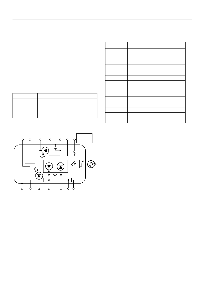
1-891a (F)
Figure 1. E3500 EM-ILM Schematic
Pin Information
Table 1. Pin Assignments
Package Type 14-pin butterfly with internal isolator
Fiber
Standard single mode
Connector
ST
RF Input
50
nominal
Bit Rate
2.5 Gb/s
10 k
@ 25 ∞C
IS
OLA
T
O
R
TEC
(
-)
(+)
(
-)
(+)
(+)
(
-)
(+)
1
2
3
4
5
6
7
14
13
12
11
9
8
NOMINAL
IMPEDANCE
50
10
CASE OR
PACKAGE
GROUNDS
Pin Number
Description
1
Thermistor
2
Thermistor
3
Laser anode
4
Power Monitor PD Anode (-)
5
Common PD Cathode (+)
6
TEC (+)
7
TEC (≠)
8
Case ground
9
Case ground
10
Wavelength Monitor PD Anode (≠)
11
Laser modulator ground
12
Modulator anode (≠)/50
RF input
13
Laser/modulator ground
14
Case ground
For additional information and latest specifications, see our website: www.triquint.com
3
E3500-Type 2.5 Gb/s Electroabsorption Modulated Isolated Laser Module
Preliminary Data Sheet
(EM-ILM) with Internal Wavelength Stabilizer for Metro and Long-Reach Applications
March 2003
Absolute Maximum Ratings
Stresses in excess of the absolute maximum ratings can cause permanent damage to the device. These are abso-
lute stress ratings only. Functional operation of the device is not implied at these or any other conditions in excess
of those given in the operations section of the data sheet. Exposure to absolute maximum ratings for extended
periods can adversely affect device reliability.
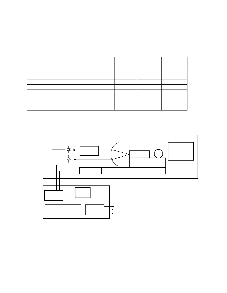
Block Diagram
Figure 2. Optics and Electronics Block Diagram
Parameter
Conditions
Limit
Unit
Laser Diode Reverse Voltage
CW
2
V
Laser Diode Forward Current
CW
150
mA
Optical Output Power
CW
10
mW
Modulator Reverse Voltage
--
5
V
Modulator Forward Voltage
--
1
V
Monitor Diode Reverse Voltage
--
10
V
Monitor Diode Forward Current
--
1
mA
Storage Temperature Range
--
≠
40 to +85
∞C
Operating Temperature Range
--
0 to 70
∞C
EML
SUBMOUNT
THERMOELECTRIC COOLER
ETALON
THERMISTOR
ISOLATOR AND
FIBER COUPLING
OPTICS
A TO D
CONVERTER
MICROPROCESSOR
D TO A
CONVERTER
EEPROM
VOLTAGE PROPORTIONAL TO WAVELENGTH
VOLTAGE PROPORTIONAL TO OPTICAL POWER
VOLTAGE PROPORTIONAL TO TEMPERATURE
EMILM MODULE
SUGGESTED
ELECTRONICS MODULE (CUSTOMER SUPPLIED)
4
For additional information and latest specifications, see our website: www.triquint.com
Preliminary Data Sheet
E3500-Type 2.5 Gb/s Electroabsorption Modulated Isolated Laser Module
March 2003
(EM-ILM) with Internal Wavelength Stabilizer for Metro and Long-Reach Applications
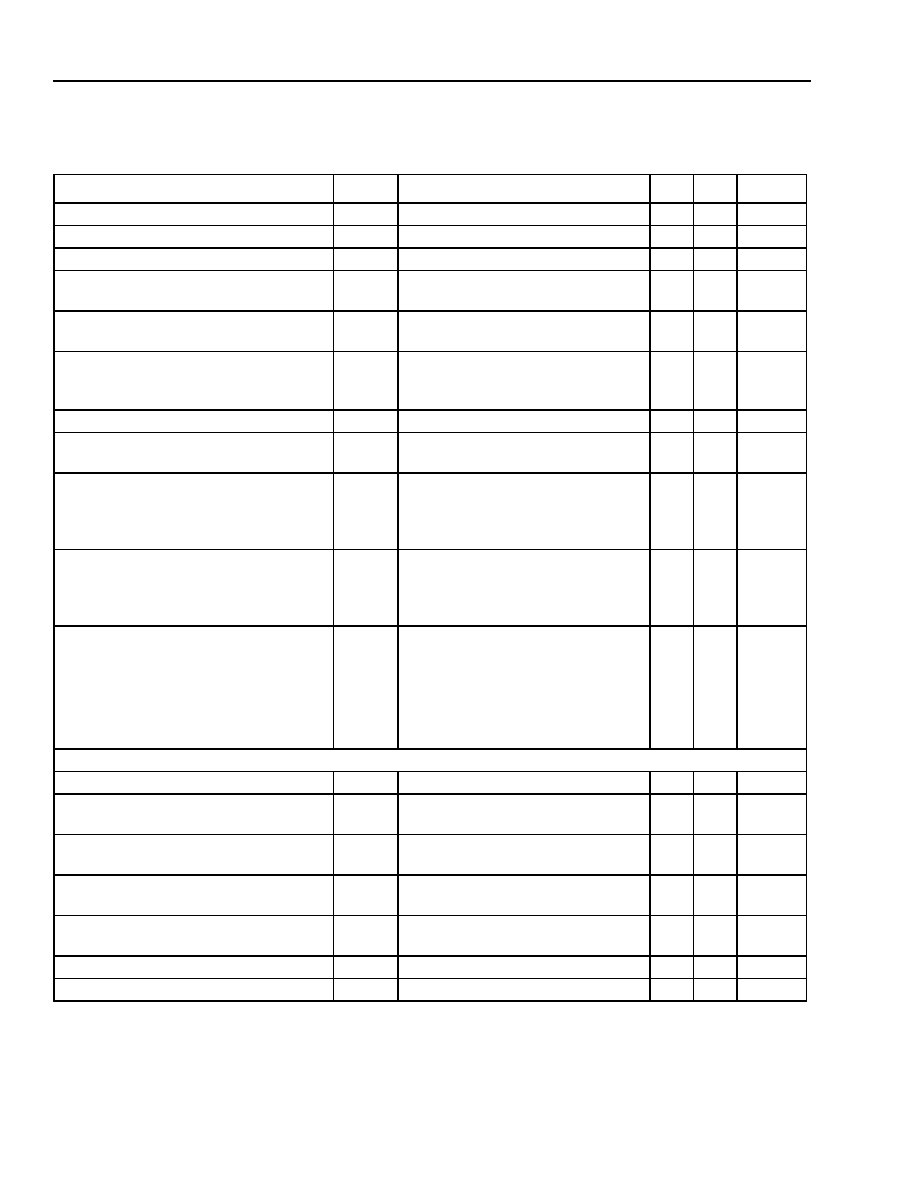
Characteristics
Table 2. Optical and Electrical Specifications
Parameter
Symbol
Conditions
Min Max
Unit
Threshold Current (BOL)
I
TH
T
LASER CHIP
= T
OP
5
35
mA
Forward Voltage
V
F
I
f
= I
OP
@ T
OP
--
2.0
V
Operating Current
I
OP
T
LASER CHIP
= T
OP
50
100
mA
Threshold Power
P
TH
T
LASER CHIP
= T
OP
I
f
= I
TH
, V
M
= 0 V
--
80
µW
Fiber Output Power (peak)
P
PK
T
LASER CHIP
= T
OP
V
M
= 0 V, I
f
= I
OP
1
--
dBm
Peak Wavelength (wavelength can be
specified to the ITU-T wavelength chan-
nels)
0
V
M
= 0 V
T
LASER CHIP
= T
OP
,
I
f
= I
OP
1530 1563
nm
Side-mode Suppression Ratio
SMSR
V
M
= 0 V, I
f
= I
OP
,T
OP
30
--
dB
Frequency Drift (EOL)
1
f
C
Operation over
20-year lifetime
--
±2.5
GHz
Time Resolved Spectroscopy (chirp):
E3505 Series
TRSp-p
2.5 Gb/s
V
LOW
= ≠1.5 V to ≠3.0 V
V
HIGH
= 0 V
If = I
OP
@ T
OP
--
0.25
≈
Time Resolved Spectroscopy (chirp):
E3502 Series
TRSp-p
2.5 Gb/s
V
LOW
= ≠1.5 V to ≠3.0 V,
V
HIGH
= ≠0.3 V
I
f
= I
OP
@ T
OP
--
0.15
≈
Dispersion Penalty
DP
2.5 Gb/s
360 km (E3505)
600 km (E3502)
V
LOW
= ≠1.5 V to ≠3.0 V
V
HIGH
= 0 V (E3505), ≠0.3 V (E3502)
I
F
= I
OP
@ T
OP
--
2.0
dB
Modulator
Extinction Ratio
ER
RF
V
M
= 0 V to ≠3.0 V, 2.5 Gb/s
10
--
dB
RF Return Loss (0 GHz to 2 GHz)
S
11
V
M
= ≠V
PP
/2
I
f
= I
OP
10
--
dB
RF Return Loss (2 GHz to 3 GHz)
S
11
V
M
= ≠V
PP
/2
I
f
= I
OP
7
--
dB
RF Return Loss (3 GHz to 5 GHz)
S
11
V
M
= ≠V
PP
/2
I
f
= I
OP
3
--
dB
≠3 dB Bandwidth
BW
V
M
= ≠V
PP
/2
I
f
= I
OP
3.5
--
GHz
Modulator Current @
V
M
= 0 V,
I
f
= 50 mA
--
--
--
15
mA
Rise/Fall Time (20% to 80%)
t
R
/t
F
--
--
125
ps
1. EOL (end of life) for a particular module is defined as the point in time when the laser drive current required to maintain the TriQuint-
specified, single specific fiber power level has increased over time by 25% from its BOL value.

For additional information and latest specifications, see our website: www.triquint.com
5
E3500-Type 2.5 Gb/s Electroabsorption Modulated Isolated Laser Module
Preliminary Data Sheet
(EM-ILM) with Internal Wavelength Stabilizer for Metro and Long-Reach Applications
March 2003
1. EOL (end of life) for a particular module is defined as the point in time when the laser drive current required to maintain the TriQuint-
specified, single specific fiber power level has increased over time by 25% from its BOL value.
2. Standard operating condition is 5.0 V reverse bias.
3. The (relative) etalon slope is defined as the local slope (in GHz
≠1
) at the TriQuint-specified ITU operating point, divided by the R_R
REF
(the
response ratio) value at the ITU operating point for the particular module under consideration. Note that the value of this (relative) slope pro-
vides information on the precision required by the customer to maintain control of the R_R
REF
ratio to provide frequency locking. For exam-
ple, 1%/GHz minimum would mean that the R_R
REF
ratio must be controlled to < ± 2.5% of its BOL TriQuint-specified value in order to
provide ± 2.5 GHz frequency stability for the module.
4. The frequency capture range (CR) is the spectral area in which the emitted wavelength must be before launching the automated wavelength
control mode. This ensures that, when going from automated power control to automated wavelength control mode, the locked wavelength
will be the targeted ITU wavelength. CR is the minimum of CR≠ and CR+ (see Figure 3).
5. Operation at a
T
of 70 ∞C ≠ T
SET
is guaranteed, where T
SET
is the laser temperature required to achieve the required ITU wavelength, over
life, in a DWDM system (T
SET
range is 15 ∞C to 35 ∞C). In a non-WDM application, T
SET
is 25 ∞C.
Figure 3. Definitions
Monitor Diode
Monitor Current
Power Monitor
Monitor PD
I
RMON
I
PD
T
LASER CHIP
= T
OP
V
BD
=
V
RMON
, I
f
= I
OP
10
10
1000
1000
µA
µA
Dark Current
I
D
T
LASER CHIP
= T
OP
, V
BD
=
V
RMON
--
0.1
µA
Monitor Reverse-bias Voltage
2
V
RMON
--
3
10
V
Etalon Slope
3
(Relative to Peak)
--
--
0.5
8
%/GHz
Frequency Capture Range
4
CR
Measured from f
ITU
toward increasing f
and decreasing f
6.5
--
GHz
Thermistor B Constant
B
--
3700 4100
--
Thermoelectric Cooler
TEC Current
I
TEC
T
LASER CHIP
= 15
∞C
T
CASE
= 70
∞
C
--
1.3
A
TEC Voltage
V
TEC
T
LASER CHIP
= 15
∞C
T
CASE
= 70
∞C
--
2.6
V
TEC Power
P
TEC
T
LASER CHIP
= 15
∞C
T
CASE
= 70
∞C
--
3.0
W
TEC Capacity
5
T
T
CASE
= 70
∞C
--
5
--
∞C
Laser Module
Optical Isolation
--
T
CASE
= 0
∞C to 65 ∞C
30
--
dB
Table 2. Optical and Electrical Specifications (continued)
Parameter
Symbol
Conditions
Min Max
Unit
CR≠
CR+
R_R
R_R
REF
ITU
CR = MIN (CR≠, CR+)
Characteristics
(continued)
6
For additional information and latest specifications, see our website: www.triquint.com
Preliminary Data Sheet
E3500-Type 2.5 Gb/s Electroabsorption Modulated Isolated Laser Module
March 2003
(EM-ILM) with Internal Wavelength Stabilizer for Metro and Long-Reach Applications
Characteristics
(continued)
1-500(C).d
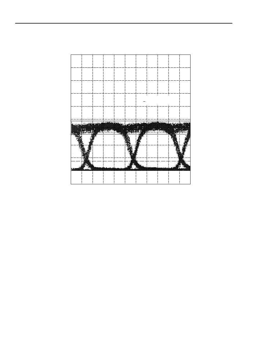
Figure 4. Typical Eye Pattern at 2.5 Gb/s
184.5 mV
I = 50
V = ≠1.04 + 2.08 pp
P= ≠0.5 dBm
≠15.5 mV
20 mV
/div
91.65 ns
100 ps/div
92.65 ns
For additional information and latest specifications, see our website: www.triquint.com
7
E3500-Type 2.5 Gb/s Electroabsorption Modulated Isolated Laser Module
Preliminary Data Sheet
(EM-ILM) with Internal Wavelength Stabilizer for Metro and Long-Reach Applications
March 2003
Characteristics
(continued)
1-930(C).c
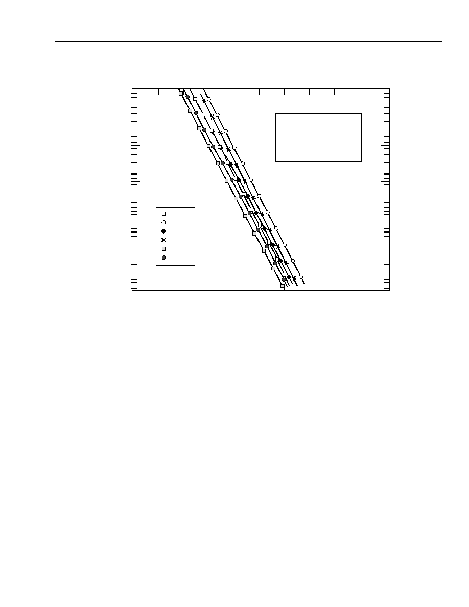
Figure 5. BER vs. Optical Power (Typical)
0 km
107 km
122 km
202 km
337 km
640 km
≠37
≠36
≠35
≠34
≠33
≠32
≠31
≠30
≠29
≠28
≠38
T = 25 PC
I
BIAS
(LASER) = 80 mA
V
BIAS
(MOD) = ≠1.0 Vdc
V
PP
(MOD) = 2.0 V
P
OUT
= 1.9 dBm (PULSED)
EXT. RATIO (RF) = 11.4 dB
TEST CONDITIONS:
10
≠12
10
≠11
10
≠10
10
≠9
10
≠8
10
≠7
10
≠6
10
≠5
OPTICAL POWER (dBm)
BER
8
For additional information and latest specifications, see our website: www.triquint.com
Preliminary Data Sheet
E3500-Type 2.5 Gb/s Electroabsorption Modulated Isolated Laser Module
March 2003
(EM-ILM) with Internal Wavelength Stabilizer for Metro and Long-Reach Applications
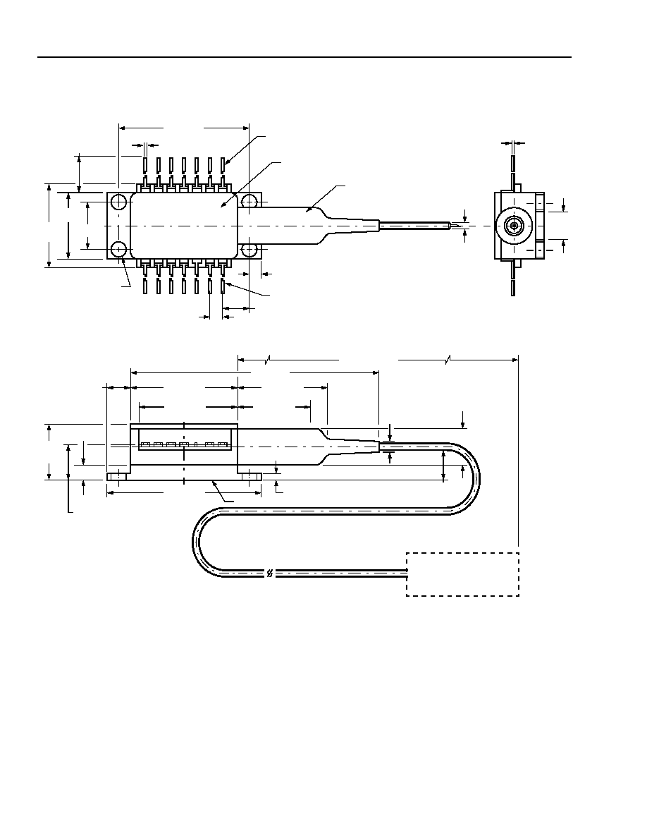
Outline Diagram
1-520.h (F)
0.180 (4.56)
HEAT SINK
0.215 (5.45)
0.056 (1.42)
0.030 (0.75)
59.06 (1500.00)
MIN
0.10
(2.5)
0.260 (6.60)
0.215
(5.47)
REF
0.036
(0.91)
PIN 1
0.078 (1.98)
0.100 (2.54) TYP
0.105 (2.67) DIA
TYP (4) PLACES
0.020 (0.51) TYP
0.500 (12.70)
MIN
STRAIN
RELIEF
PIN 14
TRADEMARK, CODE, LASER SERIAL NUMBER,
AND DATE CODE IN APPROX. AREA SHOWN
0.200
(5.08)
~
1.025 (26.04)
0.10 ± 0.002
(2.54 ± 0.051)
0.213 (5.40) TYP
0.500
(12.70)
0.350
(8.89)
0.605
(15.37)
MAX
2.03 (51.6)
0.863 (21.91)
0.575 (14.61)
0.820 (20.83)
0.700 (17.78)
0.365
(9.27)
MAX
1.180 (29.97)
For additional information and latest specifications, see our website: www.triquint.com
9
E3500-Type 2.5 Gb/s Electroabsorption Modulated Isolated Laser Module
Preliminary Data Sheet
(EM-ILM) with Internal Wavelength Stabilizer for Metro and Long-Reach Applications
March 2003
Electrostatic Discharge
CAUTION: This device is susceptible to damage as a result of electrostatic discharge. Take proper precau-
tions during both handling and testing. Follow guidelines such as JEDEC Publication No. 108-A
(Dec. 1988).
TriQuint employs a human-body model (HBM) for ESD-susceptibility testing and protection-design evaluation. ESD
voltage thresholds are dependent on the critical parameters used to define the model. A standard HBM (resistance
= 1.5 k
, capacitance = 100 pF) is widely used and can be used for comparison purposes.
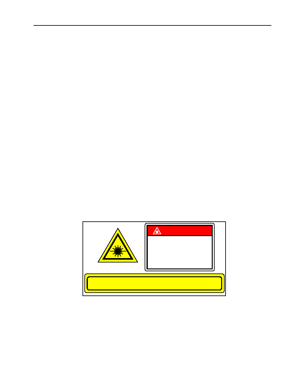
Laser Safety Information
Class IIIb Laser Product
FDA/CDRH Class IIIb laser product. All versions are Class IIIb laser products per CDRH, 21 CFR 1040 Laser Safety
requirements. All versions are classified Class 3B laser products consistent with IEC
Æ
60825-1: 1993. This device
family has been classified with the FDA under accession number 8720010. Measurements were made to classify
the product per IEC 60825-1: 1993.
This product complies with 21 CFR 1040.10 and 1040.11.
Single-mode connector.
Wavelength = 1.5 µm.
Maximum power = 10 mW.
Because of size constraints, laser safety labeling is not affixed to the module but attached to the outside of the
shipping carton.
Product is not shipped with power supply.
Caution: Use of controls, adjustments, and procedures other than those specified herein may result in
hazardous laser radiation exposure.
INVISIBLE LASER RADIATION EMITTED FROM END OF FIBER OR CONNECTOR
Avoid exposure to beam
Class IIIb Laser Product per CDRH, 21 CFR 1040
Max. Output:10 mW
Wavelength: 1.5
µm
DANGER
INVISIBLE LASER RADIATION
IS EMITTED FROM THE END
OF FIBER OR CONNECTOR
Avoid direct exposure to beam
Do not view beam directly with
optical instruments
Additional Information
For the latest specifications, additional product information, worldwide sales and distribution locations, and information about TriQuint:
Web: www.triquint.com
Tel: (503) 615-9000
E-mail: info_opto@tqs.com
Fax: (503) 615-8902
For technical questions and additional information on specific applications:
E-mail: info_opto@tqs.com
The information provided herein is believed to be reliable; TriQuint assumes no liability for inaccuracies or omissions. TriQuint assumes no responsibility for the use of this information, and all
such information shall be entirely at the user's own risk. Prices and specifications are subject to change without notice. No patent rights or licenses to any of the circuits described herein are
implied or granted to any third party.
TriQuint does not authorize or warranty any TriQuint product for use in life-support devices and/or systems.
Copyright © 2003 TriQuint Semiconductor Inc. All rights reserved.
DS03-010, March, 2003
Preliminary Data Sheet
E3500-Type 2.5 Gb/s Electroabsorption Modulated Isolated Laser Module
March 2003
(EM-ILM) with Internal Wavelength Stabilizer for Metro and Long-Reach Applica-
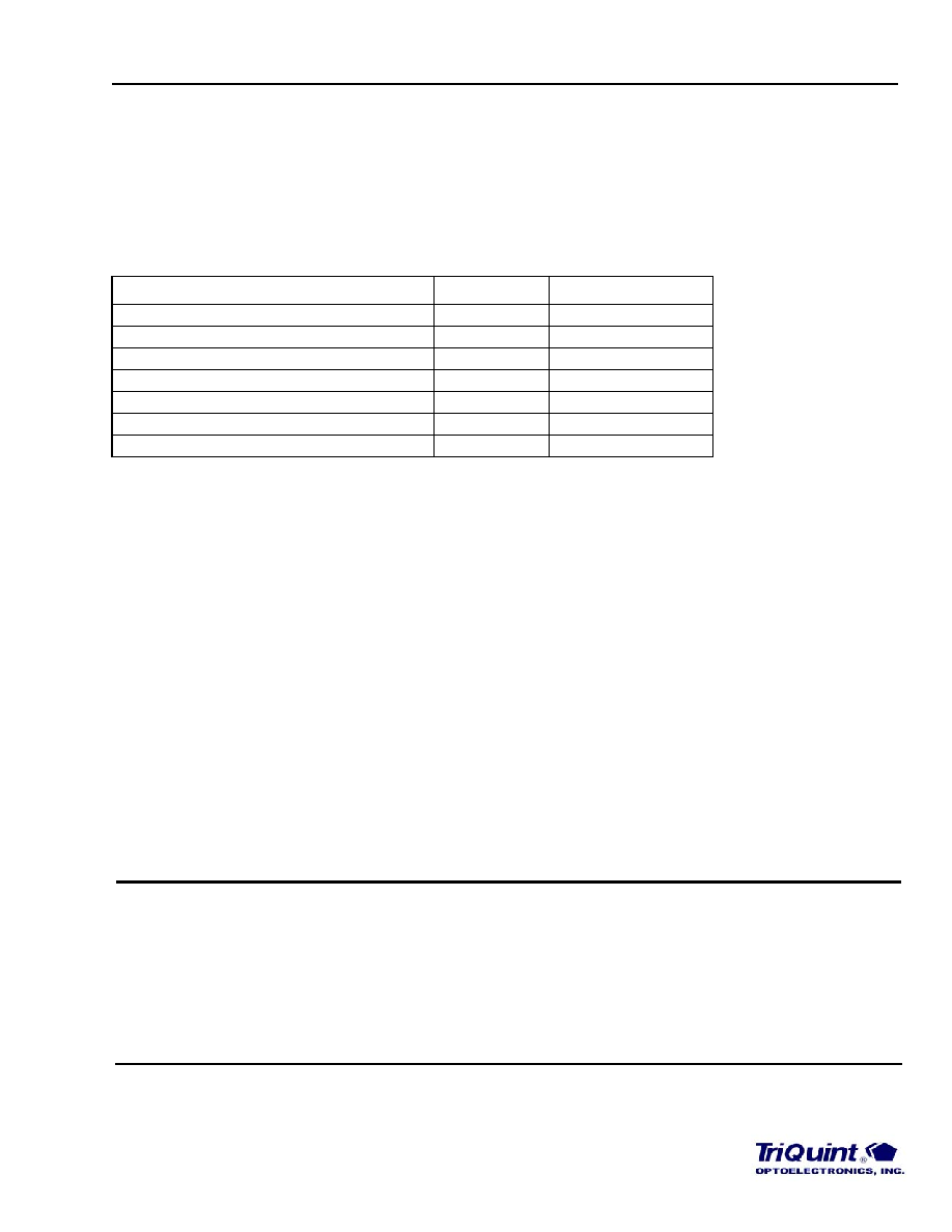
Ordering Information
To be determined.
Related Product Information
Table 3. Related Product Information
Description
Part Number
Document Number
1.5
µm EML
E2500-Type
DS01-281-1
1.5
µm DFB Laser w/ Wavelength Stabilizer
D3587-Type
DS03-009
1.5
µm Digital DFB Laser
D2500-Type
DS00-166-1
1.3
µm Digital DFB Laser
D2300-Type
DS00-167-1
1.5
µm EDFA
1724-Type
DS00-123-1
2.5 Gb/s Receiver
P172-Type
DS03-007
2.5 Gb/s Receiver with Clock Recovery
R485-Type
DS01-005-1
IEC is a registered trademark of The International Electrotechnical Commission.