DS03-030 NLP12 5-22-03 final.fm
NetLight
®
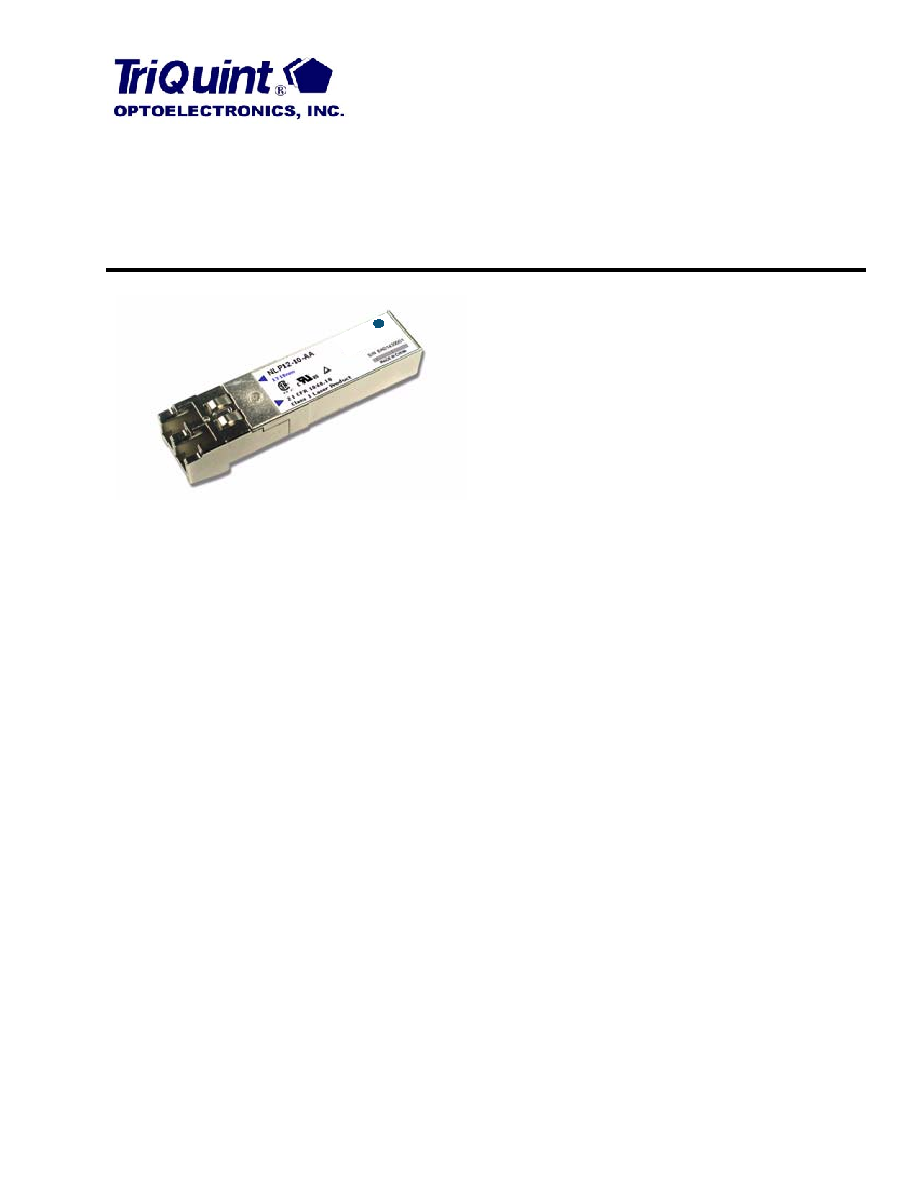
NLP12 Small Form-Factor Pluggable (SFP)
Gigabit Ethernet Laser Tranceivers
Data Sheet
May 2003
Available in a small form factor, LC Receptacle connector metal
package, the NLP12 SFP Transceiver is a high-performance,
cost-effective, optical transceiver for Gigabit Ethernet applica-
tions.
Features
Multisource agreement (MSA) compliant SFP pack-
age
LC duplex receptacle
Metal package for superior EMI performance
1550 nm DFB laser transmitter with automatic output
power control (1000BASE-LX, 80 km)
1310 nm DFB laser transmitter with automatic output
power control (1000BASE-LX, 30 km)
1310 nm FP laser transmitter with automatic output
power control (1000BASE-LX, 10 km)
850 nm VCSEL laser transmitter with automatic out-
put power control (1000BASE-SX, 550 m)
Transmitter disable input
Hot-pluggable electrical interface
Wide dynamic range GaAs PIN (1000BASE-SX) or
InGaAs PIN (1000BASE-LX) receiver
LVTTL loss-of-signal output
Low power dissipation
Single 3.3 V power supply
ac-coupled data inputs and outputs
Operating temperature range of 40 °C to +85 °C
(10 km through 80 km versions with diagnostics)
Serial identification (EEPROM)
Diagnostic monitoring per SFF-8472 standard
Benefits
Upgrade path:
-- OEMs can offer longer-reach and higher-speed
solutions, as the end user needs upgrades.
Applications
IEEE
®
802.3z 1000BASESX to 550 m
IEEE 802.3z 1000BASE-LX to 80 km
Description
The NLP12 is a line of high-speed, cost effective, small
form-factor pluggable (SFP) optical transceivers
intended for 1.25 Gb/s Gigabit Ethernet applications
from 550 m to 80 km. The transceivers feature TriQuint
Optoelectronics' optics and are packaged in a narrow-
width metal housing with an LC duplex receptacle. The
package outline and pinout conform to the multisource
SFP transceiver agreement.
The transmitter features ac-coupled differential data
inputs, and LVTTL logic level disable input and fault
indicator output. The receiver features differential ac-
coupled data outputs and an LVTTL logic level loss-of-
signal output. Diagnostic monitoring is implemented
per the SFF committee document SFF-8472.
riQ
T
uin
t
®
OP
TO
ELE
CT
RO
NIC
S, I
NC
.

2
For additional information and latest specifications, see our website: www.triquint.com
NetLight NLP12 Small Form-Factor Pluggable (SFP)
Data Sheet
Gigabit Ethernet Laser Transceiver
May 2003
Absolute Maximum Ratings
Stresses in excess of the absolute maximum ratings can cause permanent damage to the device. These are abso-
lute stress ratings only. Functional operation of the device is not implied at these or any other conditions in excess
of those given in the operations sections of the data sheet. Exposure to absolute maximum ratings for extended
periods can adversely affect device reliability.
Recommended Operating Conditions
Transceiver Timing Characteristics
1. Condition: from power on or negation of Tx_Fault using Tx_Disable.
2. Time from rising edge of Tx_Disable to when the optical output falls below 10% of nominal.
3. Time from falling edge of Tx_Disable to when the modulated optical output rises above 90% of nominal.
4. Time from fault to Tx_Fault on.
5. Time Tx_Disable must be held high to reset Tx_Fault.
6. Time from LOS state to Rx LOS assert.
7. Time from non-LOS state to Rx LOS deassert.
Parameter
Symbol
Min
Max
Unit
Storage Temperature Range
Tstg
40
85
°C
Case Temperature Range
T
C
40
85
°C
Supply Voltage
V
CC
T,
R
0
3.8
V
Parameter
Symbol
Min
Typ
Max
Unit
Case Temperature Range:
NLP12-01-AA and NLP12-01-PA
NLP12-10-AA
NLP12-10-PA
NLP12-30-PA
NLP12-80-PA
T
C
0
0
40
40
5
--
--
--
--
--
70
85
85
85
70
°C
°C
°C
°C
°C
Supply Voltage
V
CC
T, R
3.135
--
3.465
V
Data Rate
--
--
1.25
--
Gb/s
Table 1. Transceiver Timing Characteristics (see Timing Diagrams, page 9)
Parameter
Symbol
Min
Max
Unit
Time to Initialize, Including Reset of Tx_Fault
1
t_init
--
300
ms
Transmit Disable Assert Time
2
t_off
--
10
µs
Transmit Disable Negate Time
3
t_on
--
1
ms
Transmit Fault Assert Time
4
t_fault
--
100
µs
Transmit Fault Reset Time
5
t_reset
10
--
µs
Loss-of-signal Assert Time
6
t_loss_on
--
100
µs
Loss-of-signal Deassert Time
7
t_loss_off
--
100
µs
Serial ID Clock Rate
f-serial-clock
--
100
kHz

For additional information and latest specifications, see our website: www.triquint.com
3
Data Sheet
NetLight NLP12 Small Form-Factor Pluggable (SFP)
May 2003
Gigabit Ethernet Laser Transceiver
Transceiver Optical and Electrical Characteristics, NLP12-01-AA
1. TP2 refers to compliance point specified in 802.3z, section 38.2.1.
2. Differential operation is necessary for optimum performance.
3. LVTTL compatible interface.
1. 2
7
1 PRBS with a BER of 1 x 10
12
.
2. The stressed receiver sensitivity is measured using the conformance test signal defined in 802.3z, section 38.6.11.
3. Differential operation is necessary for optimum performance.
Table 2. Transmitter Optical and Electrical Characteristics (T
C
= 0 °C to 70 °C, V
CC
= 3.135 V--3.465 V)
Parameter
Symbol
Min
Max
Unit
Average Optical Output Power
Average Optical Output Power (Tx Disabled)
P
O
P
O DIS
9.5
--
3
40
dBm
dBm
Optical Wavelength
C
830
850
nm
Spectral Width
RMS
--
0.85
nm
Dynamic Extinction Ratio
EXT
9
--
dB
Optical Output Rise/Fall Time (20%80%)
t
R
/t
F
--
300
ps
Total Transmitter Jitter added at TP2
1
T
J
--
227
ps
Relative Intensity Noise
RIN
--
117
dB/Hz
Power Supply Current
I
CCT
--
150
mA
Input Data Voltage--Differential
2
V
IN
p-p
300
1600
mVp-p
Transmit Disable Voltage
3
V
D
V
CC
1.3
V
CC
V
Transmit Enable Voltage
3
V
EN
V
EE
V
EE
+ 0.8
V
Transmit Fault Output Voltage Level
V
FAULTH
V
FAULTL
V
CC
1.3
V
EE
V
CC
V
EE +
0.8
V
V
Table 3. Receiver Optical and Electrical Characteristics (T
C
= 0 °C to 70 °C, V
CC
= 3.135 V--3.465 V)
Parameter
Symbol
Min
Max
Unit
Average Sensitivity
1
P
I
--
17
dBm
Stressed Receiver Sensitivity:
2
62.5
µm Fiber
50
µm Fiber
P
STRESS
P
STRESS
--
--
12.5
13.5
dBm
dBm
Maximum Input Power
1
(Overload)
P
MAX
3
--
dBm
Optical Return Loss
ORL
12
--
dB
Power Supply Current
I
CCR
--
150
mA
Power Supply Noise Rejection Ratio
PSNR
--
100
mV
Output Data--Differential
3
V
OUT
p-p
370
2000
mVp-p
Data Output Rise/Fall Time (20%--80%)
t
R
/t
F
--
260
ps
Loss-of-Signal Voltage Level
V
LOSH
V
LOSL
V
CC
1.3
V
EE
V
CC
V
EE +
0.8
V
V
Loss-of-Signal
Assert
Deassert
P
LOSA
P
LOSD
34
34
18
17.5
dBm
dBm
LOS Hysteresis
P
HYS
0.5
6
dB

4
For additional information and latest specifications, see our website: www.triquint.com
NetLight NLP12 Small Form-Factor Pluggable (SFP)
Data Sheet
Gigabit Ethernet Laser Transceiver
May 2003
Transceiver Optical and Electrical Characteristics, NLP12-01-PA
1. TP2 refers to compliance point specified in 802.3z, section 38.2.1.
2. Differential operation is necessary for optimum performance.
3. LVTTL compatible interface.
1. 2
7
1 PRBS with a BER of 1 x 10
12
.
2. The stressed receiver sensitivity is measured using the conformance test signal defined in 802.3z, section 38.6.11.
3. Differential operation is necessary for optimum performance.
Table 4. Transmitter Optical and Electrical Characteristics (T
C
= 0 °C to 70 °C, V
CC
= 3.135 V--3.465 V)
Parameter
Symbol
Min
Max
Unit
Average Optical Output Power
Average Optical Output Power (Tx Disabled)
P
O
P
O DIS
9.5
--
3
40
dBm
dBm
Optical Wavelength
C
830
850
nm
Spectral Width
RMS
--
0.85
nm
Dynamic Extinction Ratio
EXT
9
--
dB
Optical Output Rise/Fall Time (20%80%)
t
R
/t
F
--
260
ps
Total Transmitter Jitter added at TP2
1
T
J
--
227
ps
Relative Intensity Noise
RIN
--
117
dB/Hz
Power Supply Current
I
CCT
--
150
mA
Input Data Voltage--Differential
2
V
IN
p-p
300
1600
mVp-p
Transmit Disable Voltage
3
V
D
V
CC
1.3
V
CC
V
Transmit Enable Voltage
3
V
EN
V
EE
V
EE
+ 0.8
V
Transmit Fault Output Voltage Level
V
FAULTH
V
FAULTL
V
CC
1.3
V
EE
V
CC
V
EE +
0.8
V
V
Table 5. Receiver Optical and Electrical Characteristics (T
C
= 0 °C to 70 °C, V
CC
= 3.135 V--3.465 V)
Parameter
Symbol
Min
Max
Unit
Average Sensitivity
1
P
I
--
17
dBm
Stressed Receiver Sensitivity:
2
62.5
µ
m Fiber
50
µ
m Fiber
P
STRESS
P
STRESS
--
--
12.5
13.5
dBm
dBm
Maximum Input Power
1
(Overload)
P
MAX
3
--
dBm
Optical Return Loss
ORL
12
--
dB
Power Supply Current
I
CCR
--
150
mA
Power Supply Noise Rejection Ratio
PSNR
--
100
mV
Output Data--Differential
3
V
OUT
p-p
370
2000
mVp-p
Data Output Rise/Fall Time (20%--80%)
t
R
/t
F
--
260
ps
Loss-of-Signal Voltage Level
V
LOSH
V
LOSL
V
CC
1.3
V
EE
V
CC
V
EE +
0.8
V
V
Loss-of-Signal
Assert
Deassert
P
LOSA
P
LOSD
34
34
18
17.5
dBm
dBm
LOS Hysteresis
P
HYS
0.5
6
dB

For additional information and latest specifications, see our website: www.triquint.com
5
Data Sheet
NetLight NLP12 Small Form-Factor Pluggable (SFP)
May 2003
Gigabit Ethernet Laser Transceiver
Transceiver Optical and Electrical Characteristics, NLP12-10-AA
1. TP2 refers to compliance point specified in 802.3z, section 38.2.1.
2. Differential operation is necessary for optimum performance.
3. LVTTL compatible interface.
1. 2
7
1 PRBS with a BER of 1 x 10
12
.
2. The stressed receiver sensitivity is measured using the conformance test signal defined in 802.3z, section 38.6.11.
3. Differential operation is necessary for optimum performance.
Table 6. Transmitter Optical and Electrical Characteristics (T
C
= 0 °C to 85 °C, V
CC
= 3.135 V--3.465 V)
Parameter
Symbol
Min
Max
Unit
Average Optical Output Power
Average Optical Output Power (Tx Disabled)
P
O
P
O DIS
9.5
--
3
40
dBm
dBm
Optical Wavelength
C
1270
1355
nm
Spectral Width
RMS
--
2.8
nm
Dynamic Extinction Ratio
EXT
9
--
dB
Optical Output Rise/Fall Time (20%80%)
t
R
/t
F
--
260
ps
Total Transmitter Jitter added at TP2
1
T
J
--
227
ps
Relative Intensity Noise
RIN
--
120
dB/Hz
Power Supply Current
I
CCT
--
150
mA
Input Data Voltage--Differential
2
V
IN
p-p
300
1600
mVp-p
Transmit Disable Voltage
3
V
D
V
CC
1.3
V
CC
V
Transmit Enable Voltage
3
V
EN
V
EE
V
EE
+ 0.8
V
Transmit Fault Output Voltage Level
V
FAULTH
V
FAULTL
V
CC
1.3
V
EE
V
CC
V
EE +
0.5
V
V
Table 7. Receiver Optical and Electrical Characteristics (T
C
= 0 °C to 85 °C, V
CC
= 3.135 V--3.465 V)
Parameter
Symbol
Min
Max
Unit
Average Sensitivity
1
P
I
--
20
dBm
Stressed Receiver Sensitivity
2
P
STRESS
--
14.4
dBm
Maximum Input Power
1
(Overload)
P
MAX
3
--
dBm
Optical Return Loss
ORL
12
--
dB
Power Supply Current
I
CCR
--
150
mA
Power Supply Noise Rejection Ratio
PSNR
--
100
mV
Output Data--Differential
3
V
OUT
p-p
400
1200
mVp-p
Data Output Rise/Fall Time (20%--80%)
t
R
/t
F
--
260
ps
Loss-of-Signal Voltage Level
V
LOSH
V
LOSL
V
CC
1.3
V
EE
V
CC
V
EE +
0.8
V
V
Loss-of-Signal
Assert
Deassert
P
LOSA
P
LOSD
34
34
21
20.5
dBm
dBm
LOS Hysteresis
P
HYS
0.5
6
dB
Document Outline
- Features
- Benefits
- Applications
- Description
- Absolute Maximum Ratings
- Recommended Operating Conditions
- Transceiver Timing Characteristics
- Transceiver Optical and Electrical Characterisitics
- List of Tables
- Table 1. Transceiver Timing Characteristics (see Timing Diagrams, page�9)
- Table 2. Transmitter Optical and Electrical Characteristics (TC = 0 �C to 70 �C, VCC = 3.135 V3....
- Table 3. Receiver Optical and Electrical Characteristics (TC = 0 �C to 70 �C, VCC = 3.135 V3.465 V)
- Table 4. Transmitter Optical and Electrical Characteristics (TC = 0 �C to 70 �C, VCC = 3.135 V3....
- Table 5. Receiver Optical and Electrical Characteristics (TC = 0 �C to 70 �C, VCC = 3.135 V3.465 V)
- Table 6. Transmitter Optical and Electrical Characteristics (TC = 0 �C to 85 �C, VCC = 3.135 V3....
- Table 7. Receiver Optical and Electrical Characteristics (TC = 0 �C to 85 �C, VCC = 3.135 V3.465 V)
- Table 8. Transmitter Optical and Electrical Characteristics (TC =
40 �C to 85 �C, VCC = 3.135 V...
- Table 9. Receiver Optical and Electrical Characteristics (TC =
40 �C to 85 �C, VCC = 3.135 V3.4...
- Table 10. Transmitter Optical and Electrical Characteristics (TC =
40 �C to 85 �C, VCC = 3.135 V...
- Table 11. Receiver Optical and Electrical Characteristics (TC =
40 �C to 85 �C, VCC = 3.135 V3....
- Table 12. Transmitter Optical and Electrical Characteristics (TC =
40 �C to 85 �C, VCC = 3.135 V...
- Table 13. Receiver Optical and Electrical Characteristics (TC =
40 �C to 85 �C, VCC = 3.135 V3....
- Table 14. Transceiver Pin Descriptions
- Table 15. EEPROM Serial ID Memory Contents, 1000BASE-SX Version (NLP12-01-AA)
- Table 16. EEPROM Serial ID Memory Contents, 1000BASE-SX Version with Diagnostics (NLP12-01-PA)
- Table 17. EEPROM Serial ID Memory Contents, 1000BASE-LX Version (NLP12-10-AA)
- Table 18. EEPROM Serial ID Memory Contents, 1000BASE-LX Version with Diagnostics (NLP12-10-PA)
- Table 19. EEPROM Serial ID Memory Contents, 30 km Version with Diagnostics (NLP12-30-PA)
- Table 20. EEPROM Serial ID Memory Contents, 80 km Version with Diagnostics (NLP12-80-PA)
- Table 21. Regulatory Compliance
- Table 22. Ordering Information
- Transceiver Timing Diagrams
- List of Figures
- Power Supply Information
- Electrical Schematic
- Pin Information
- EEPROM Information
- Electrostatic Discharge
- Qualification and Reliability
- Outline Drawings
- Laser Safety Information
- Ordering Information
- Contact Information