P173P OC-48/STM-16 MiniDIL PIN Receiver
with Improved Sensitivity
Advance Data Sheet
July 2003
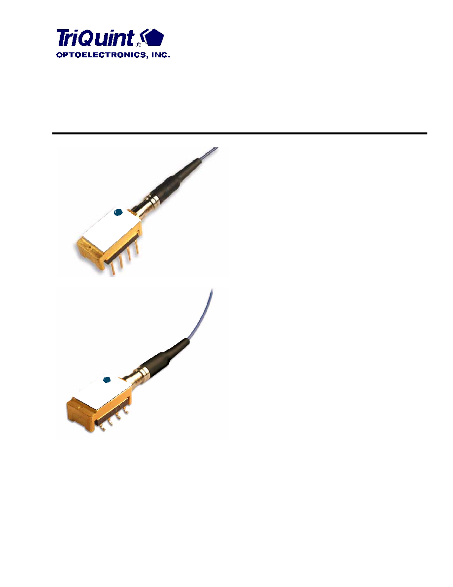
The P173-Type PIN/Preamp receivers are available in a mini-DIL
package (top) or a gull-wing package (bottom).
Features
s
Low-profile, 8-lead mini-DIL or gull-wing style pack-
age:
-- Suitable for SONET/SDH applications
s
Metal package:
-- Offers superior shielding for high noise
immunity
s
Planar structure for high reliability
s
Operating wavelength range:
-- 1.25
�
m to 1.6
�
m
s
Wide operating temperature range:
-- �40
�
C to +85
�
C
s
Scheduled to be qualified according to Telcordia
Technologies
TM GR-468-CORE
s
Single 3.3 V or 5 V power supply
s
Typical sensitivity: �25.5 dBm
s
Typical overload: +1 dBm
s
Built-in thermistor
Applications
s
Long-reach or metro SONET OC-48 and
SDH STM-16, or multidata-rate telecommunications
applications
s
SONET/SDH receivers and transponders
s
Line terminal equipment
Benefits
s
Compact size
s
Easily board mounted
�
riQ
T
ui
nt
SE
M
IC
O
ND
UC
TO
R
P1
73
-T
yp
e
Re
ce
iv
er
�
riQ
T
ui
nt
SE
M
IC
ON
DU
CT
OR
P1
73
2
2
For additional information and latest specifications, see our website: www.triquint.com
P173P OC-48/STM-16 MiniDIL PIN Receiver
Advance Data Sheet
with Improved Sensitivity
July 2003
Description
The P173-type receiver consists of an PIN coupled to a
single-mode fiber pigtail and a linear preamplifier. The
PIN is a rear-illuminated planar diode structure with a
low-capacitance active area for maximum responsivity
and speed.
This device incorporates the new Laser 2000 manufac-
turing process from the Optoelectronics Products unit
of TriQuint Semiconductor. Laser 2000 is a low-cost
platform that targets high-volume manufacturing and
tight product distributions on all optical subassemblies.
This platform incorporates an advanced optical design
that is produced on TriQuint's highly automated pro-
duction lines. The Laser 2000 platform is qualified for
central office and uncontrolled environments, and can
be used for applications requiring high performance
and low cost.
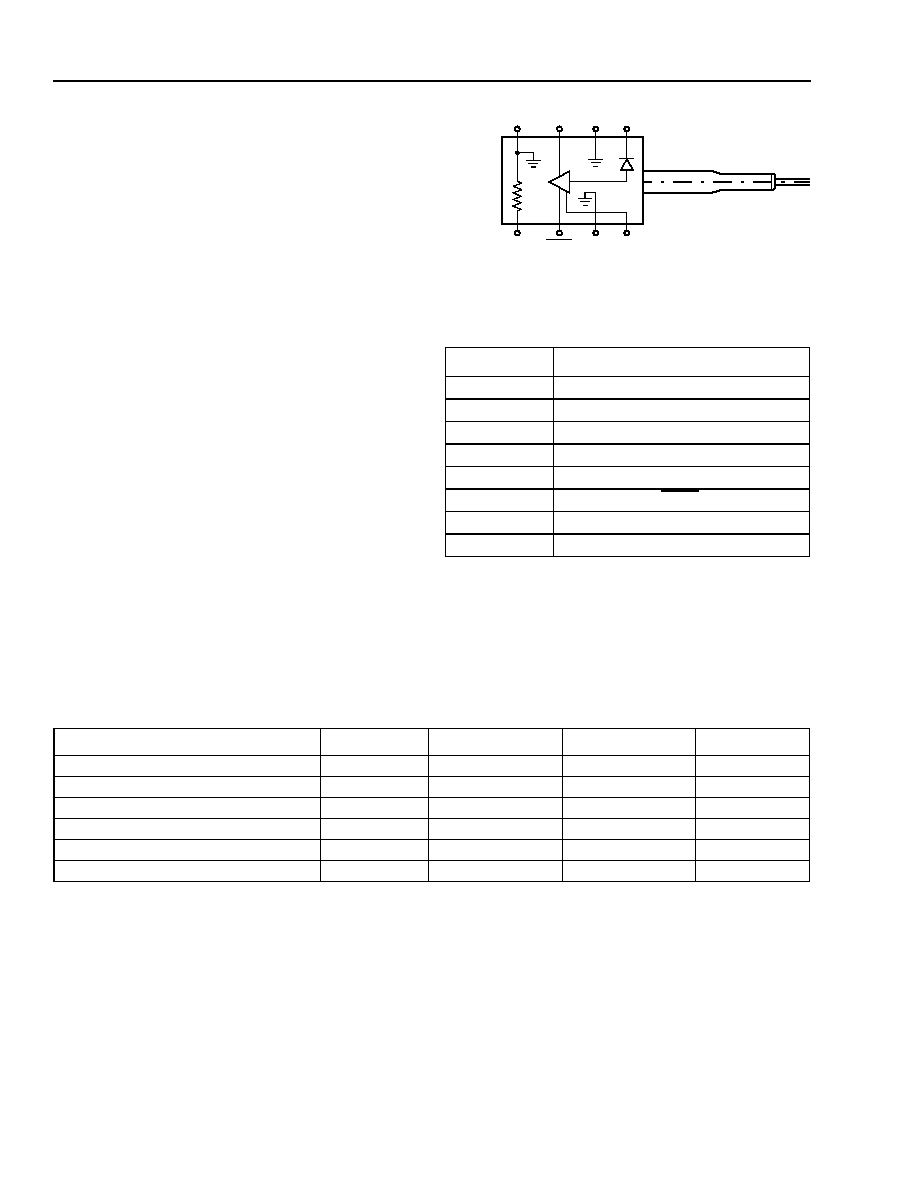
Figure 1. P173P PIN/Preamp (Top View)
* Logic high when light is on.
Logic low when light is on.
Table 1. P173-Type PIN/Preamp Pin Descriptions
Pin Number
Description
1
Photodiode Bias
2
Case Ground
3
DATA*
4
Case Ground
5
Thermistor
6
DATA
7
Case Ground
8
V
CC
1-902(F).c
4
3
2
1
5
6
7
8
DATA
DATA
V
CC
THERMISTOR
GND
V
PD
GND
GND
Absolute Maximum Ratings
Stresses in excess of the absolute maximum ratings can cause permanent damage to the device. These are abso-
lute stress ratings only. Functional operation of the device is not implied at these or any other conditions in excess
of those given in the operational sections of the data sheet. Exposure to absolute maximum ratings for extended
periods can adversely affect device reliability.
Electrostatic Discharge
CAUTION: This device is susceptible to damage as a result of electrostatic discharge. Take proper precau-
tions during both handling and testing. Follow guidelines such as EIA
�
Standard EIA-625.
TriQuint Semiconductor employs a human-body model (HBM) for ESD-susceptibility testing and protection-design
evaluation. ESD voltage thresholds are dependent on the critical parameters used to define the model. A standard
HBM (resistance = 1.5 k
, capacitance = 100 pF) is widely used and can be used for comparison purposes.
Parameter
Symbol
Min
Max
Unit
Positive Supply Voltage
V
CC
�0.5
6.0
V
Optical Input Power
P
IN
--
8
dBm
Operating Case Temperature Range
T
C
�40
85
�
C
Storage Temperature Range
T
stg
�40
85
�
C
Lead Soldering Temperature
--
--
250
�
C
Lead Soldering Time
--
--
10
s

For additional information and latest specifications, see our website: www.triquint.com
3
Advance Data Sheet
P173P OC-48/STM-16 MiniDIL PIN Receiver
July 2003
with Improved Sensitivity
Electrical Characteristics
Minimum and maximum values specified over operating case temperature range and end of life (EOL), and typical
values are for 25
�
C and beginning of life (BOL), unless otherwise specified
Table 2. Electrical Characteristic
Parameter
Symbol
Min
Typ
Max
Unit
dc Power Supply Voltages:
Positive Supply
PIN Operating Bias Voltage
V
CC
V
PD
3.15
3
3.3
5
5.25
15
V
V
dc Power Supply Currents:
Positive Supply (at V
CC
= 3.3 V)
Positive Supply (at V
CC
= 5 V)
PIN Bias Supply at V
OP
I
CC3.3
I
CC5
I
APD
--
--
--
45
60
--
60
80
4
mA
mA
mA
dc Power Dissipation (at V
CC
= 3.3 V)
dc Power Dissipation (at V
CC
= 5 V)
P
DISS3.3
P
DISS5
--
--
150
300
200
420
mW
mW
Single-ended, Small Signal (<10
�
A) Transimped-
ance
T
z
--
4
--
k
TIA Input Noise Current (100 kHz--2 GHz)
N
rms
--
130
--
nArms
Output Return Loss (130 MHz--5 GHz)
S
22
--
�15
�9
dB
3 dB Bandwidth
1
1. Measured relative to 60 MHz at -20 dBm optical power .
f
C
1.8
2.5
--
GHz
Thermistor resistance
2
2. Measured at 25
o
C. The resistance of the thermistor is inversely proportional to the temperature. The temperature T
k
in degree-Kelvin can be
calculated from the resistance value using the Steinhart-Hart equation: 1/T
k
= A + B ln(R
TH
) + C [ ln(R
TH
) ]
3
, where R
TH
is the resistance and A,
B, and C are constants: A = +1.0267 x 10
�3
;
B = +2.565 x 10
�4
;
C = -4.5421 x 10
�8
.
The temperature in degree-Celsius is T
c
= T
k
- 273.15
R
TH
9.5
10
10.5
k

4
For additional information and latest specifications, see our website: www.triquint.com
P173P OC-48/STM-16 MiniDIL PIN Receiver
Advance Data Sheet
with Improved Sensitivity
July 2003
Optical Characteristics
Minimum and maximum values specified over operating case temperature range and end of life (EOL), and typical
values are for 25
�
C, and beginning of life (BOL), unless otherwise specified.
Table 3. Optical Characteristics
Parameter
Conditions
Symbol
Min
Typ
Max
Unit
Optical Wavelength
At Rated Sensitivity
1250
--
1610
nm
Responsivity
1
1. V
CC
= 3.3 V, V
PD
= 5 V, OSNR > 40 dB, using a Maxim 3265 limiting amp.
1310 nm, -30 dBm, 25
�
C
R
0.75
--
--
A/W
Sensitivity
1
1310 nm, 2.5 Gb/s, 2
23
� 1 PRBS,
1x10
�10
BER, 10 dB Extinction Ratio:
At 25
�
C
At �40
�
C to +85
�
C
P
RMIN
--
--
�25.5
�25.0
�24
�23
dBm
dBm
Overload
1
1550 nm, 2.5 Gb/s, 2
23
� 1 PRBS,
1x10
�10
BER, 10 dB Extinction Ratio
P
RMAX
0
+1
--
dBm
Optical Return Loss
Optical Return Loss
ORL
--
--
�27
dB
For additional information and latest specifications, see our website: www.triquint.com
5
Advance Data Sheet
P173P OC-48/STM-16 MiniDIL PIN Receiver
July 2003
with Improved Sensitivity
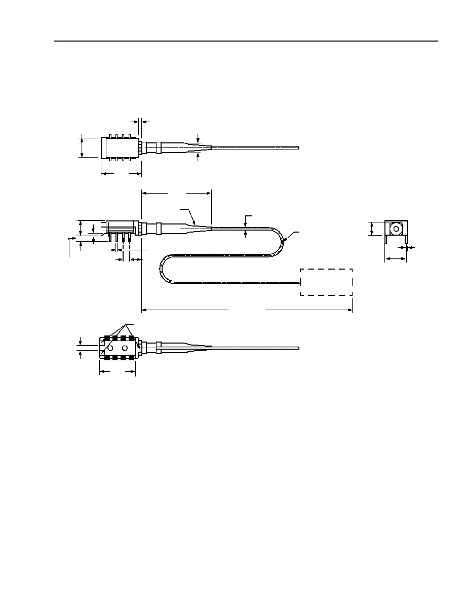
Outline Diagrams
P173-Type Through-Hole Package
Dimensions are in inches and (millimeters).
0.170
(4.32)
CONNECTOR
FIBER
0.900 �m
BEND LIMITER
0.974
(24.74)
MIN.
0.016 (0.41) 8 PLACES
0.155
(3.94)
STANDOFF
0.010 (0.25) MAX
0.079
(2.01)
0.431
(10.95)
FIBER LENGTH
0.010
(0.25)
0.300
(7.62)
8 PLACES
0.100
(2.54)
MIN
0.315
(8.00)
4 3 2 1
5 6 7 8
0.045 (1.14)
NOSE GEOMETRY
0.565
(14.35)
0.144
(3.66)
0.010
(0.25)
0.194
(4.95)
LEAD TRIM
1-1057F
6
For additional information and latest specifications, see our website: www.triquint.com
P173P OC-48/STM-16 MiniDIL PIN Receiver
Advance Data Sheet
with Improved Sensitivity
July 2003
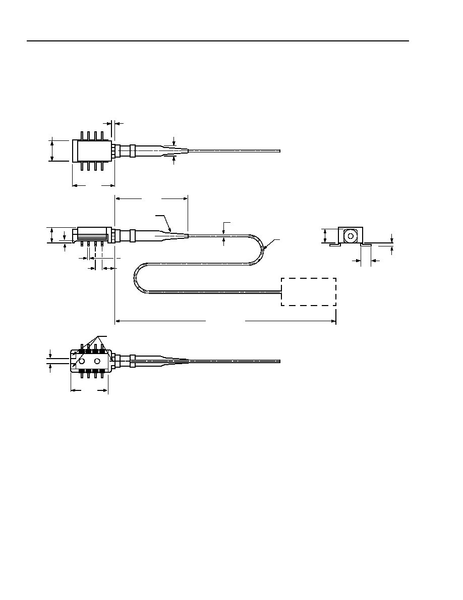
Outline Diagrams
(continued)
P173-Type Gull-Wing Package
Dimensions are in inches and (millimeters).
0.170
(4.32)
0.315
(8.00)
4
3 2
1
5
6 7
8
0.045 (1.14)
NOSE GEOMETRY
CONNECTOR
FIBER
0.900 M
BEND LIMITER
0.974
(24.74)
MIN.
0.565
(14.35)
0.144
(3.66)
0.016 (0.41) 8 PLACES
0.155
(3.94)
STANDOFF
0.010(0.25) MAX
0.079
(2.01)
0.431
(10.95)
FIBER LENGTH
0.047
�
0.008
(1.19
�
0.20)
0.100
(2.54)
MIN
0.020
�
0.005
(0.50)
�
0.010
(0.25)
0.194
(4.95)
1-1057F.a

For additional information and latest specifications, see our website: www.triquint.com
7
Advance Data Sheet
P173P OC-48/STM-16 MiniDIL PIN Receiver
July 2003
with Improved Sensitivity
Qualification Information
The P173-type receiver is scheduled to complete the following qualification tests and meet the intent of Telcordia
Technologies GR-468-CORE.
Table 4. P173-Type Qualification Information
Test
Reference
Conditions
Sample Size
Pass/Fail Criteria
Mechanical
Shock
MIL-STD-883
Method 2002
Condition B
5 times/axis
500 G, 1 ms
11
Change in receiver
sensitivity: 1 dB
Vibration
MIL-STD-883
Method 2007
Condition A
20 G, 20 Hz--2000 Hz
4 min./cycle
4 cycles/axis
11
Change in receiver
sensitivity: 1 dB
Thermal Shock
MIL-STD-883
Method 1011
0
�
C to 100
�
C,
20 cycles
Reference to P172
Physical Attributes and
Leak Check
Lead Integrity
MIL-STD-883
Method 2004
Condition A
To Be Provided by
the Supplier
--
Solderability
MIL-STD-883
Method 2003
--
To Be Provided by
the Supplier
--
Fiber Pull
--
1 kg; 3 times; 5 s
Reference to P172
Change in receiver
sensitivity: 1 dB
Accelerating
Aging (HTOB)
MIL-STD-883
Method 1005
85
�
C under bias,
2000 hours
Reference to P172
Change in receiver
sensitivity: 1 dB
Low-temperature
Storage
--
�40
�
C storage 2000
hours
Reference to P172
Change in receiver
sensitivity: 1 dB
High-temperature
Storage
--
85
�
C storage
2000 hours
11
Change in receiver
sensitivity: 1 dB
Temperature
Cycling
Telcordia Technologies
GR-468-CORE,
Section 5.20
�40
�
C to +85
�
C, 100
cycles
11
Change in receiver
sensitivity: 1 dB
Damp Heat
MIL-STD-883
Method 103
85
�
C/85% RH 1000
hours
Reference to P172
Change in receiver
sensitivity: 1 dB
Cyclic Moisture
Resistance
Telcordia Technologies
GR-468-CORE,
Section 5.23
--
Reference to P172
Change in receiver
sensitivity: 1 dB
ESD Threshold
Telcordia Technologies
GR-468-CORE,
Section 5.22
Human Body Model
6
Threshold minimum
500 V
Internal Moisture
MIL-STD-883
Method 1018
5000 ppm water vapor Reference to P172
Change in receiver
sensitivity: 1 dB
Flammability
UL94
V0
Reference to P172
--
Additional Information
For the latest specifications, additional product information, worldwide sales and distribution locations, and information about TriQuint:
Web: www.triquint.com
Tel: (503) 615-9000
E-mail: info_opto@tqs.com
Fax: (503) 615-8902
For technical questions and additional information on specific applications:
E-mail: info_opto@tqs.com
The information provided herein is believed to be reliable; TriQuint assumes no liability for inaccuracies or omissions. TriQuint assumes no responsibility for the use of this information, and all
such information shall be entirely at the user's own risk. Prices and specifications are subject to change without notice. No patent rights or licenses to any of the circuits described herein are
implied or granted to any third party.
TriQuint does not authorize or warranty any TriQuint product for use in life-support devices and/or systems.
Copyright � 2003 TriQuint Semiconductor Inc. All rights reserved.
DS03-039 July, 2003
P173P OC-48/STM-16 MiniDIL PIN Receiver
Advance Data Sheet
with Improved Sensitivity
July 2003
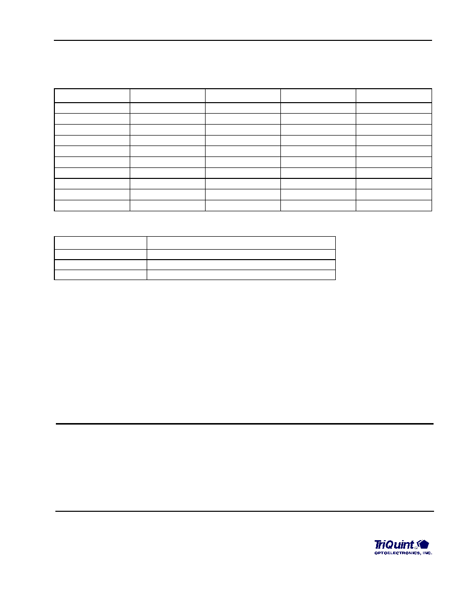
Ordering Information
Table 5. P173-Type Receiver Ordering Information
Product Code
Detector Type
Connector type
Lead type
Fiber type
P173PBCA
PIN
SC/PC
Through Hole
SMF
P173PBCF
PIN
FC/PC
Through Hole
SMF
P173PBCJ
PIN
MU
Through Hole
SMF
P173PBCJJ
PIN
MU-J
Through Hole
SMF
P173PBCS
PIN
LC
Through Hole
SMF
P173PCCA
PIN
SC/PC
Gull Wing
SMF
P173PCCF
PIN
FC/PC
Gull Wing
SMF
P173PCCJ
PIN
MU
Gull Wing
SMF
P173PCCJJ
PIN
MU-J
Gull Wing
SMF
P173PCCS
PIN
LC
Gull Wing
SMF
Table 6. Related Product Information
Product Code
Description
P172
2.5 Gb/s miniDIL Receiver
R485
2.5 Gb/s Receiver with Clock Recovery
R480
2.5 Gb/s Receiver with CML Data Output
Telcordia Technologies is a trademark of Telcordia Technologies, Inc.
EIA is a registered trademark of the Electronic Industries Association.