 | –≠–Ľ–Ķ–ļ—ā—Ä–ĺ–Ĺ–Ĺ—č–Ļ –ļ–ĺ–ľ–Ņ–ĺ–Ĺ–Ķ–Ĺ—ā: TGF4124 | –°–ļ–į—á–į—ā—Ć:  PDF PDF  ZIP ZIP |
TriQuint Semiconductor Texas Phone: 972 994-8465 Fax 972 994-8504
Web: www.triquint.com
1
4124
∑
0.5 um gate finger length
∑
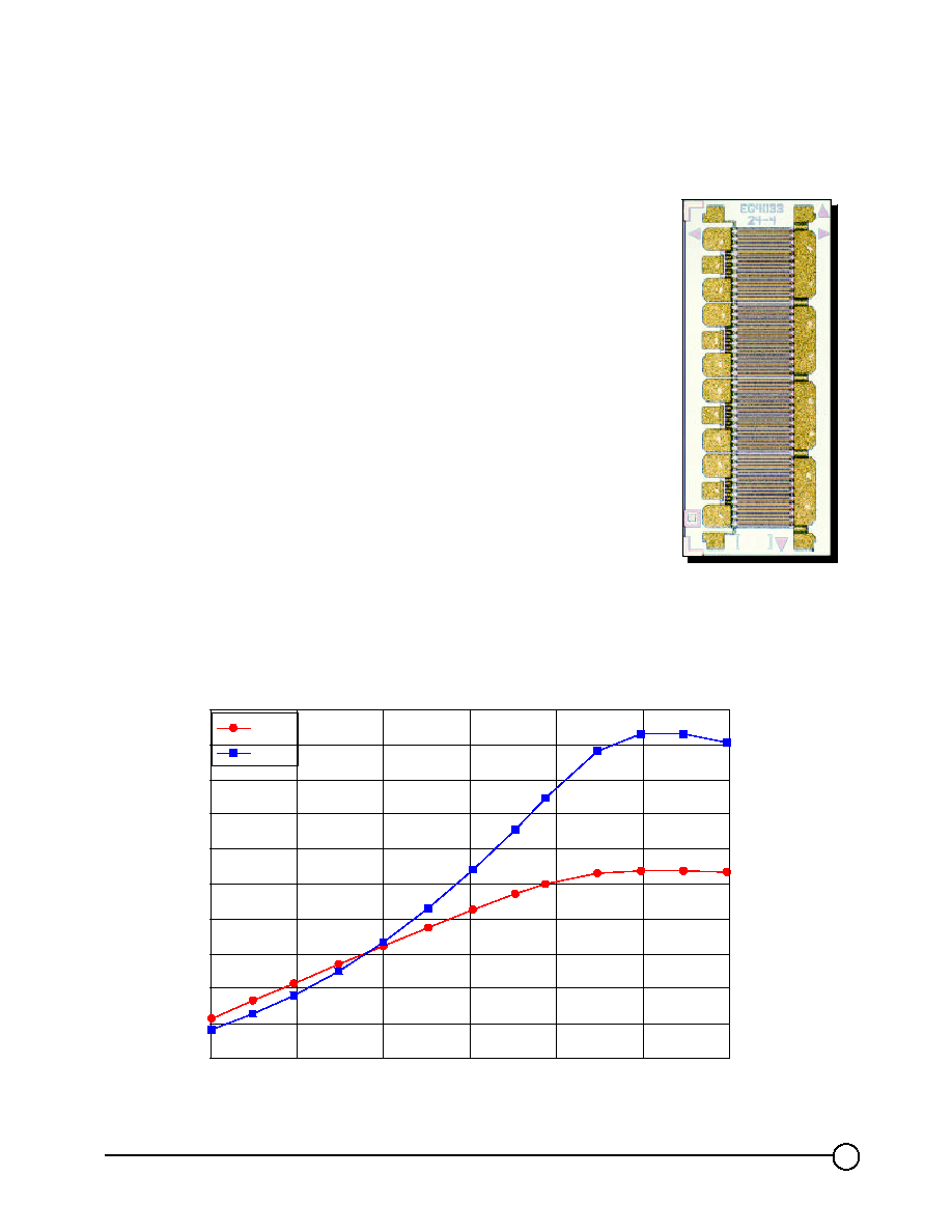
Nominal Pout of 12 Watts at 2.3 GHz
∑
Nominal PAE of 51.5% at 2.3 GHz
∑
Nominal Gain of 10.8 dB at 2.3 GHz
∑
Die size 36.0 x 81.0 x 4.0 mils
(0.914 x 2.057 x 0.102 mm)
TGF4124-EPU RF Performance at F = 2.3 GHz
Vd = 8.0 V, Vg = -1.1 V, Iq = 2.17 A and T
A
= 25įC
30
32
34
36
38
40
42
44
46
48
50
20
22
24
26
28
30
32
Input Power (dBm)
Output Power (dBm)
5
10
15
20
25
30
35
40
45
50
55
Power Added Efficiency %
Pout
PAE
24 mm Discrete HFET
TGF4124-EPU
TriQuint Semiconductor Texas Phone: 972 994-8465 Fax 972 994-8504
Web: www.triquint.com
2
40
50
60
70
80
90
100
110
120
130
140
Predicted Channel Temp (įC)
32
33
34
35
36
37
38
39
40
41
42
Output Power (dBm)
Vg = -1.1V
Vg = -1.3 V
Vg = -1.5 V
Pout
Tch
5
10
15
20
25
30
35
40
45
50
55
Power Added Efficiency %
Vg = -1.1V
Vg = -1.3 V
Vg = -1.5 V
7
8
9
10
11
12
13
14
20
21
22
23
24
25
26
27
28
29
30
31
32
Input Power (dBm)
Gain (dB)
Vg = -1.1V
Vg = -1.3 V
Vg = -1.5 V
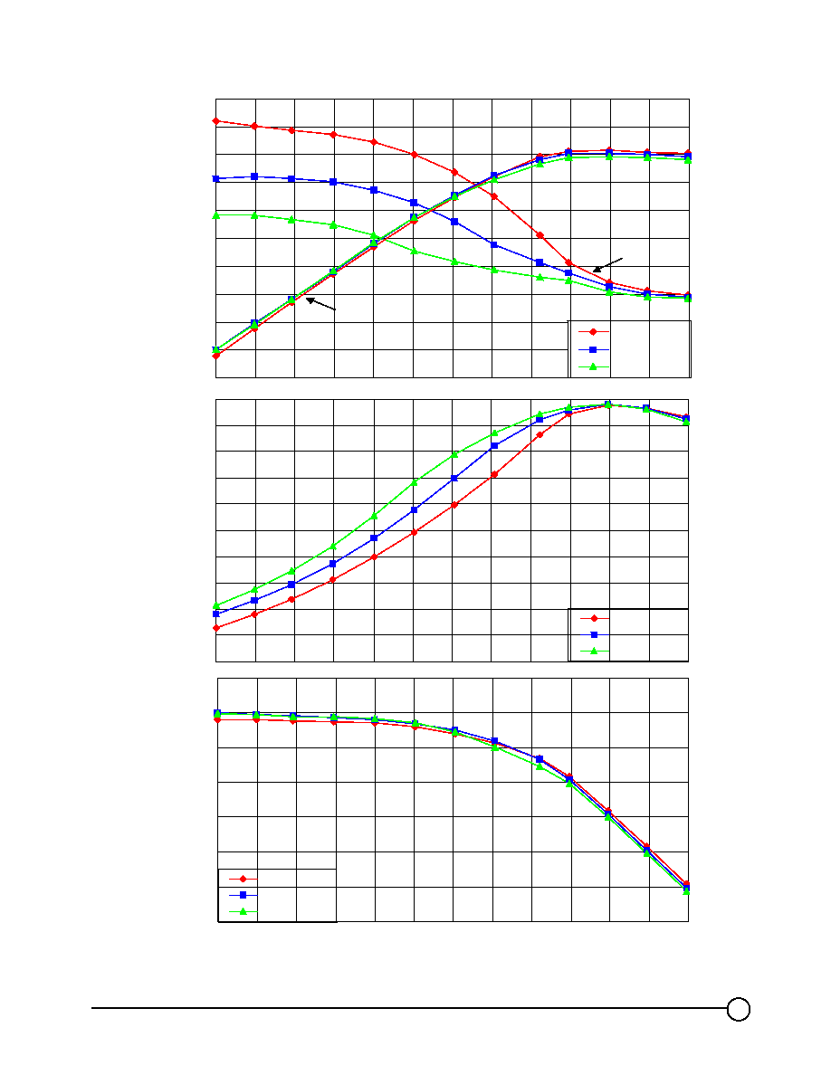
TGF4124-EPU RF Performance for Vd = 7.0 V, F = 2.3 GHz, and T
A
= 25
į
C
Quiescent Id is 2.24 A (Vg = -1.1 V), 1.81 A (Vg = -1.3 V), and 1.37 A (Vg = -1.5 V)
TriQuint Semiconductor Texas Phone: 972 994-8465 Fax 972 994-8504
Web: www.triquint.com
3
50
60
70
80
90
100
110
120
130
140
150
Predicted Channel Temp (įC)
32
33
34
35
36
37
38
39
40
41
42
Output Power (dBm)
Vg = -1.1V
Vg = -1.3 V
Vg = -1.5 V
Pout
Tch
5
10
15
20
25
30
35
40
45
50
55
Power Added Efficiency %
Vg = -1.1V
Vg = -1.3 V
Vg = -1.5 V
7
8
9
10
11
12
13
14
20
21
22
23
24
25
26
27
28
29
30
31
32
Input Power (dBm)
Gain (dB)
Vg = -1.1V
Vg = -1.3 V
Vg = -1.5 V
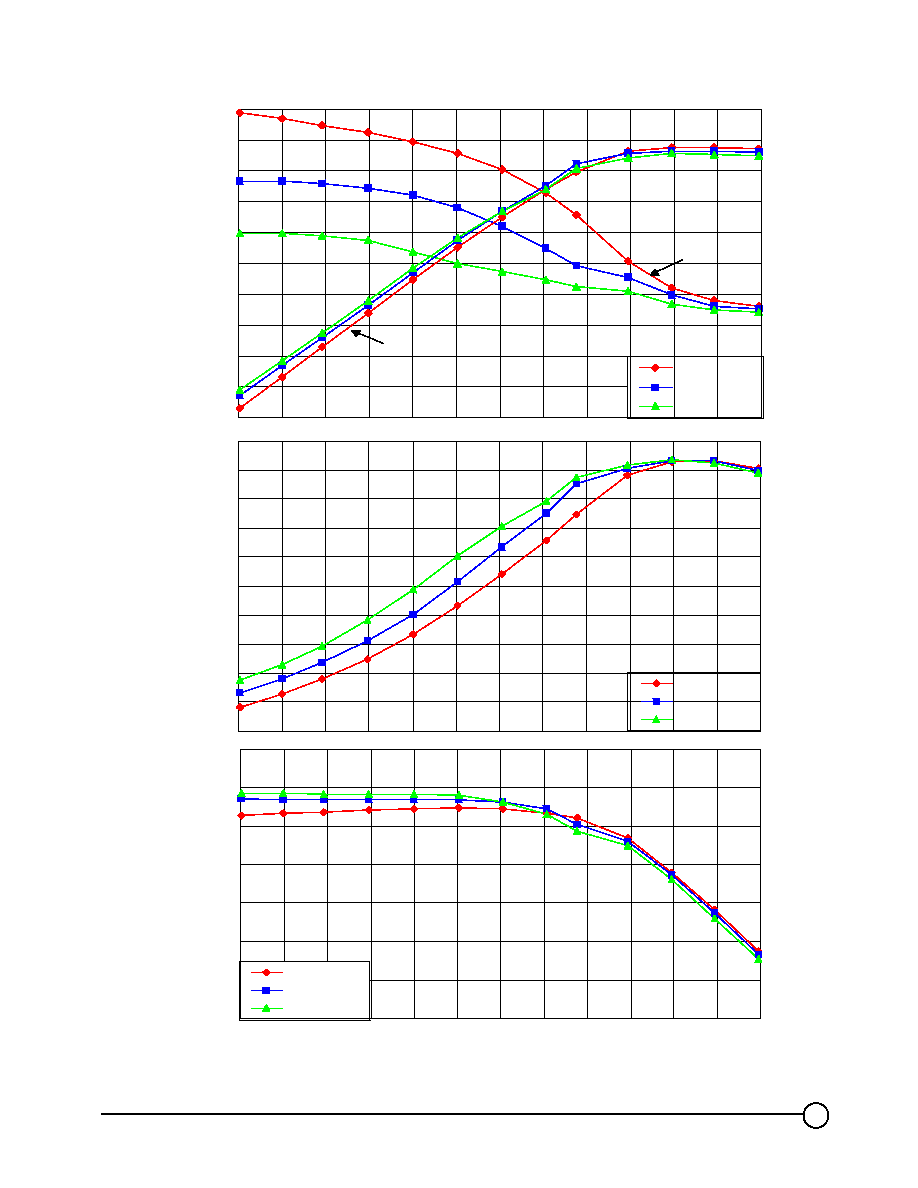
TGF4124-EPU RF Performance for Vd = 8.0 V, F = 2.3 GHz, and T
A
= 25
į
C
Quiescent Id is 2.17 A (Vg = -1.1 V), 1.80 A (Vg = -1.3 V), and 1.40 A (Vg = -1.5 V)
TriQuint Semiconductor Texas Phone: 972 994-8465 Fax 972 994-8504
Web: www.triquint.com
4
60
70
80
90
100
110
120
130
140
150
160
170
Predicted Channel Temp (įC)
31
32
33
34
35
36
37
38
39
40
41
42
Output Power (dBm)
Vg = -1.1V
Vg = -1.3 V
Vg = -1.5 V
Pout
Tch
5
10
15
20
25
30
35
40
45
50
55
Power Added Efficiency %
Vg = -1.1V
Vg = -1.3 V
Vg = -1.5 V
7
8
9
10
11
12
13
14
20
21
22
23
24
25
26
27
28
29
30
31
32
Input Power(dBm)
Gain (dB)
Vg = -1.1V
Vg = -1.3 V
Vg = -1.5 V
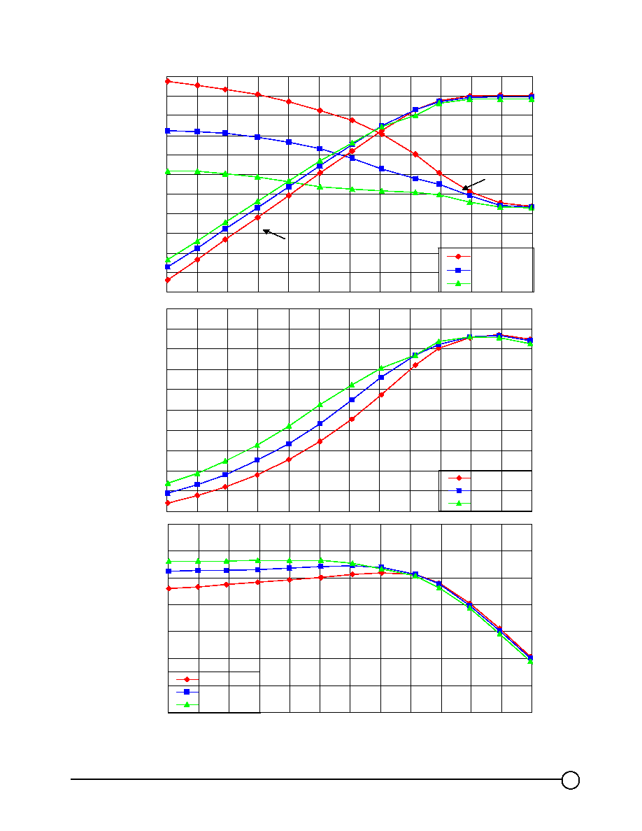
TGF4124-EPU RF Performance for Vd = 9.0 V, F = 2.3 GHz, and T
A
= 25
į
C
Quiescent Id is 2.11 A (Vg = -1.79 V), 1.79 A (Vg = -1.3 V), and 1.43 A (Vg = -1.5 V)
TriQuint Semiconductor Texas Phone: 972 994-8465 Fax 972 994-8504
Web: www.triquint.com
5
DC Characteristics for the TGF4124-EPU
DC probe Parameters
Nominal
Unit
IDSS
Drain Saturation Current
5880
mA
GM
Transconductance
3960
mS
VP
Pinch Off Voltage
-1.85
V
BVGS
Breakdown Voltage Gate-Source
-22
V
BVGD
Breakdown Voltage Gate-Drain
-22
V
0
5 0 0
1 0 0 0
1 5 0 0
2 0 0 0
2 5 0 0
3 0 0 0
3 5 0 0
4 0 0 0
4 5 0 0
5 0 0 0
5 5 0 0
6 0 0 0
0
1
2
3
4
5
6
7
8
9
D r a in V o lta g e ( V )
Drain Current (mA)
Absolute Maximum Ratings
Drain-to-source Voltage, Vds................................. ... ... ... ... ... ... ... ... ... ... ... ... ... ... ... ..........12 V
Gate-to-source Voltage, Vgs..................... ... ... ... ... ... ... ... ... ... ... ... ... ... ... ... .............-5 V to 0 V
Mounting Temperature.................... ... ... ... ... ... ... ... ... ... ... ... ... ... ... .... ............ ... ... ... ... ... 320įC
Storage Temperature........................ ... ... ... ... ... ... ... ... ... ... ... ... ... .... ................ -65įC to 200įC
Power Dissipation.............. ... ... ... ... .... ... ... ... ... ... ... ... ... ... ... ... ... ... ... ...refer to Thermal Model
Operating Channel Temperature... ... ... ... ... ... ... ... ... ... ... ... ... ... ... ... ..... .refer to Thermal Model
Stresses beyond those listed under absolute maximum ratings may cause permanent damage to the device.
These are stress ratings only, and functional operation of the device at these or any other conditions beyond
those indicated in this document is not implied. Exposure to absolute maximum rated conditions for extended
periods of time may affect device reliability.
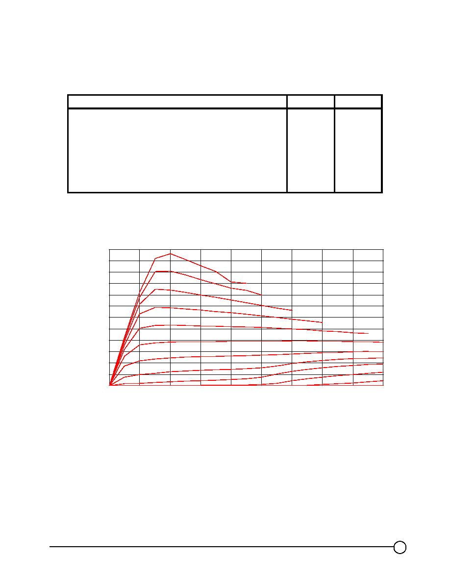
Example of DC I-V Curves
Vg = 0.0 V to -2.75 V in 0.25 steps T
A
= 25
į
C


