TriQuint Semiconductor Texas: Phone (972)994-8465 Fax (972)994 8504 Web: www.triquint.com
Advanced Product Information
March 7, 2003
1
Note: Devices designated as EPU are typically early in their characterization process prior to finalizing all electrical and process
specifications. Specifications are subject to change without notice.
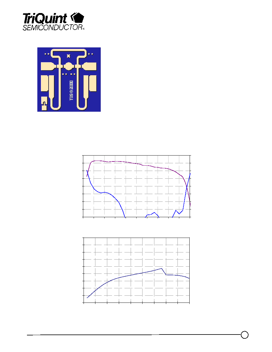
Wideband Dual Stage VPIN Limiter
TGL2201-EPU
Key Features
·
3-25 GHz Passive, High Isolation Limiter
·
Low Loss < 0.5 dB , X-band
·
Good Return Loss > 15 dB
·
Flat Leakage < 18 dBm
·
Input Power CW Survivability > 5W
·
Integrated DC Block on both input and output
·
Chip Dimensions: 1.1 x 1.1 x 0.1 mm
Primary Applications
·
Military Radar
·
LNA Receiver Chain Protection
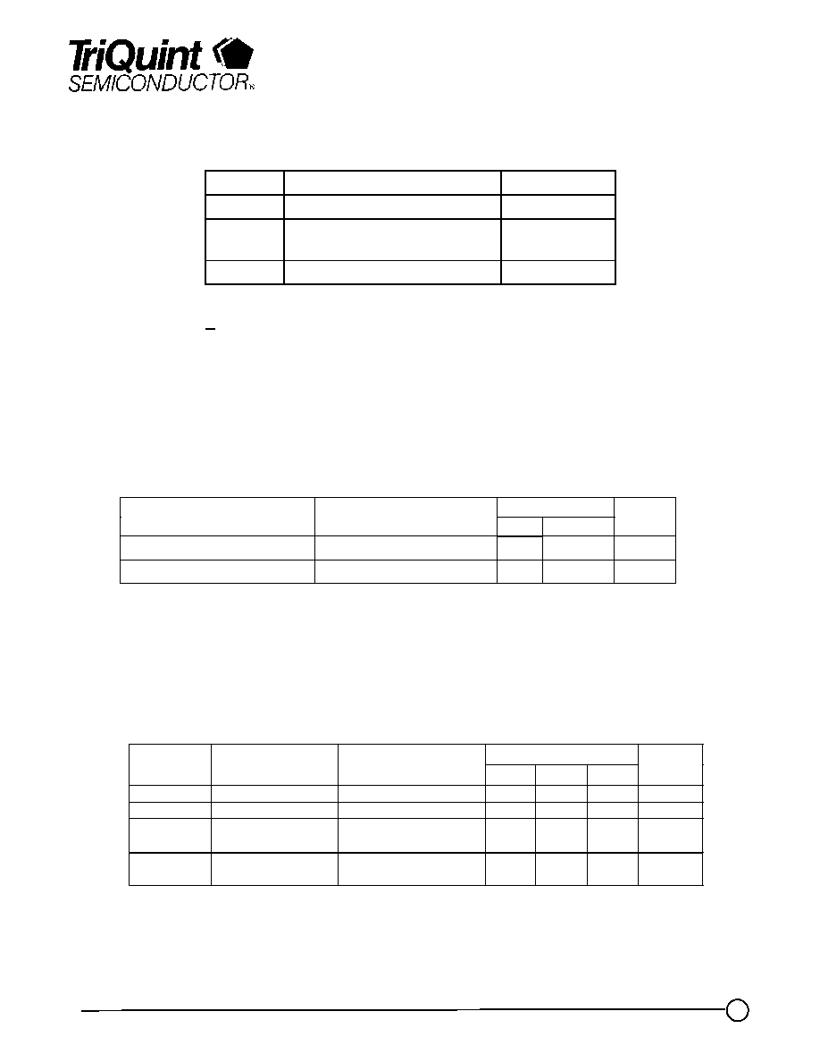
Fixtured Measured Performance
-4.0
-3.5
-3.0
-2.5
-2.0
-1.5
-1.0
-0.5
0.0
0
3
6
9
12
15
18
21
24
27
30
Frequency (GHz)
In
ser
tio
n
L
o
ss (d
B)
-24
-21
-18
-15
-12
-9
-6
-3
0
R
e
tu
r
n
L
o
ss (d
B
)
8
10
12
14
16
18
20
22
24
26
9
12
15
18
21
24
27
30
33
36
Input Power (dBm)
Ou
tp
u
t
Po
we
r (d
Bm)
Data taken @ 10 GHz
TriQuint Semiconductor Texas: Phone (972)994-8465 Fax (972)994 8504 Web: www.triquint.com
Advanced Product Information
March 7, 2003
2
Note: Devices designated as EPU are typically early in their characterization process prior to finalizing all electrical and process
specifications. Specifications are subject to change without notice.
TGL2201-EPU
TABLE III
RF CHARACTERISTICS
(T
A
= 25
°C)
Limit
Symbol
Parameter
Test Condition
Min
Typ
Max
Units
IL
Insertion Loss
F = 4-20 GHz
--
0.5
1.0
dB
IRL
Input Return Loss F = 4-20 GHz
12
--
--
dB
ORL
Output Return
Loss
F = 4-20 GHz
12
--
--
dB
PWR
Output Power @
P
in
= 27 dBm
F = 6.0 GHz
F = 16.0 GHz
--
--
--
--
20
20
dBm
dBm
TABLE II
DC CHARACTERISTICS
(T
A
= 25
°C)
Limit
Symbol
Parameter
Min
Max
Units
FWD_RES
(D1, D2, D3, D4)
Resistance Forward
1.9
3.9
Ohm
VREV
(D1,D4)
Reverse Voltage
-60
-30
V
TABLE I
MAXIMUM
RATINGS
Symbol
Parameter 1/
Value
P
IN
Input Continuous Wave Power
37 dBm
T
M
Mounting Temperature
(30 Seconds)
320
0
C
T
STG
Storage Temperature
-65 to 150
0
C
1/ These ratings represent the maximum operable
values for this device
TriQuint Semiconductor Texas: Phone (972)994-8465 Fax (972)994 8504 Web: www.triquint.com
Advanced Product Information
March 7, 2003
3
Note: Devices designated as EPU are typically early in their characterization process prior to finalizing all electrical and process
specifications. Specifications are subject to change without notice.
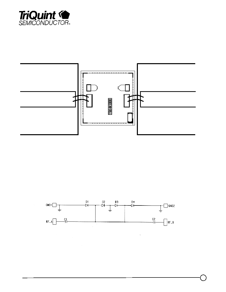
High Isolation Limiter Assembly
TGL2201-EPU
DC Schematic
RF In
RF Out
TriQuint Semiconductor Texas: Phone (972)994-8465 Fax (972)994 8504 Web: www.triquint.com
Advanced Product Information
March 7, 2003
4
Note: Devices designated as EPU are typically early in their characterization process prior to finalizing all electrical and process
specifications. Specifications are subject to change without notice.
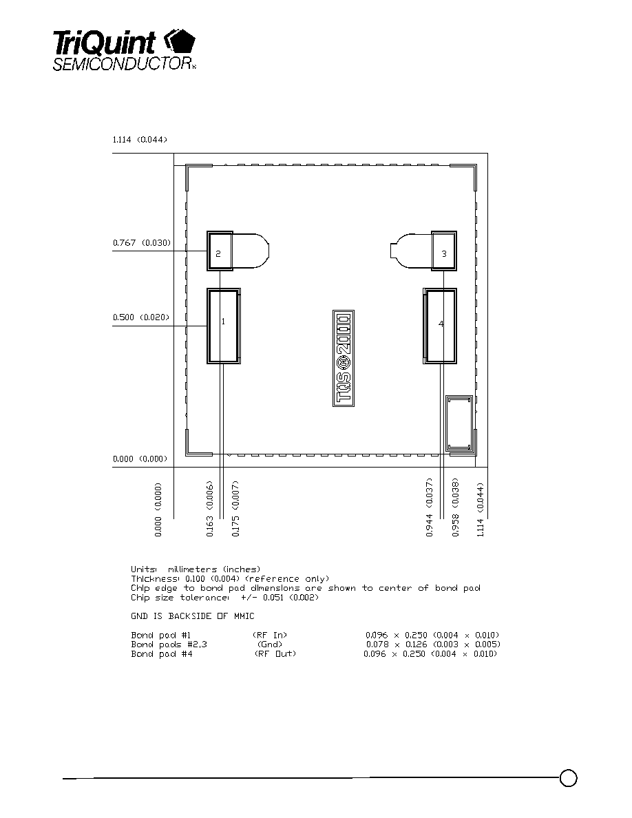
Mechanical Drawing
TGL2201-EPU
GaAs MMIC devices are susceptible to damage from Electrostatic Discharge. Proper precautions should
be observed during handling, assembly and test.
TriQuint Semiconductor Texas: Phone (972)994-8465 Fax (972)994 8504 Web: www.triquint.com
Advanced Product Information
March 7, 2003
5
Note: Devices designated as EPU are typically early in their characterization process prior to finalizing all electrical and process
specifications. Specifications are subject to change without notice.
TGL2201-EPU
Assembly Process Notes
GaAs MMIC devices are susceptible to damage from Electrostatic Discharge. Proper precautions should
be observed during handling, assembly and test.
Reflow process assembly notes:
· Use AuSn (80/20) solder with limited exposure to temperatures at or above 300 °C for 30 sec
· An alloy station or conveyor furnace with reducing atmosphere should be used.
· No fluxes should be utilized.
· Coefficient of thermal expansion matching is critical for long-term reliability.
· Devices must be stored in a dry nitrogen atmosphere.
Component placement and adhesive attachment assembly notes:
· Vacuum pencils and/or vacuum collets are the preferred method of pick up.
· Air bridges must be avoided during placement.
· The force impact is critical during auto placement.
· Organic attachment can be used in low-power applications.
· Curing should be done in a convection oven; proper exhaust is a safety concern.
· Microwave or radiant curing should not be used because of differential heating.
· Coefficient of thermal expansion matching is critical.
Interconnect process assembly notes:
· Thermosonic ball bonding is the preferred interconnect technique.
· Force, time, and ultrasonics are critical parameters.
· Aluminum wire should not be used.
· Maximum stage temperature is 200 °C.