1SMB5926 THRU 1SMB5956
SURFACE MOUNT SILICON ZENER DIODE
VOLTAGE - 11 TO 200 Volts Power - 1.5 Watts
FEATURES
l
For surface mounted applications in order to
optimize board space
l
Low profile package
l
Built-in strain relief
l
Glass passivated junction
l
Low inductance
l
Typical I
R
less than 1 A above 11V
l
High temperature soldering :
260 /10 seconds at terminals
l
Plastic package has Underwriters Laboratory
Flammability Classification 94V-O
MECHANICAL DATA
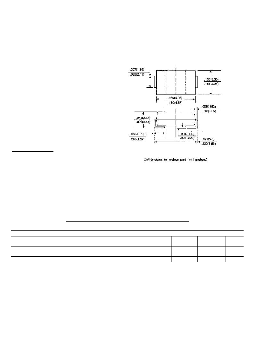
Case: JEDEC DO-214AA Molded plastic over
passivated junction
Terminals: Solder plated, solderable per MIL-STD-750,
method 2026
Polarity: Color band denotes positive end (cathode)
Standard Packaging: 12mm tape (EIA-481)
Weight: 0.003 ounce, 0.093 gram
MAXIMUM RATINGS AND ELECTRICAL CHARACTERISTICS
Ratings at 25 ambient temperature unless otherwise specified.
SYMBOL
VALUE
UNITS
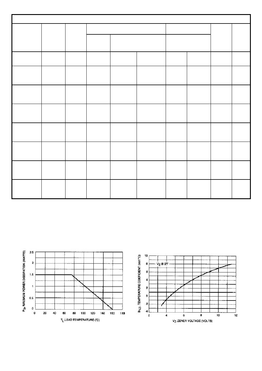
DC Power Dissipation @ T
L
=75 , Measure at Zero Lead Length(Note 1, Fig. 1)
Derate above 75
P
D
1.5
15
Watts
mW/
Peak forward Surge Current 8.3ms single half sine-wave superimposed on rated
load(JEDEC Method) (Note 1,2)
I
FSM
10
Amps
Operating Junction and Storage Temperature Range
T
J
,T
STG
-55 to +150
NOTES:
1. Mounted on 5.0mm
2
(.013mm thick) land areas.
2. Measured on 8.3ms, single half sine-wave or equivalent square wave, duty cycle = 4 pulses
per minute maximum.
3. ZENER VOLTAGE (Vz) MEASUREMENT Nominal zener voltage is measured with the device
function in thermal equilibrium with ambient temperature at 25 .
4.ZENER IMPEDANCE (Zz) DERIVATION Z
ZT
and Z
ZK
are measured by dividing the ac voltage drop across
the device by the accurrent applied. The specified limits are for I
Z(ac)
= 0.1 I
Z
, (dc) with the ac freqency = 60Hz.
DO-214AA
MODIFIED J-BEND
1SMB5926 THRU 1SMB5956
ELECTRICAL CHARACTERISTICS (T
L
=30 unless otherwise noted) (V
F
=1.5Volts Max @ I
F
=200mAdc for all types.)
Maximum Zener Impedance (Note 2.)
Max reverse
Leakage Current
Device
Nominal
Zener
Voltage
Vz @ I
ZT
volts
(Note 1.)
Test
current
I
ZT
mA
Z
ZT
@ I
ZT
Ohms
Z
Zk
@ I
ZK
Ohms
@
I
ZK
mA
I
R
A
@
V
R
Volts
Maximum
DC Zener
Current
I
ZM
mAdc
Device
Marking
Code
1SMB5926
1SMB5927
1SMB5928
11
12
13
34.1
31.2
28.8
5.5
6.5
7
550
550
550
0.25
0.25
0.25
1
1
1
8.4
9.1
9.9
136
125
115
926B
927B
928B
1SMB5929
1SMB5930
1SMB5931
1SMB5932
15
16
18
20
25
23.4
20.8
18.7
9
10
12
14
600
600
650
650
0.25
0.25
0.25
0.25
1
1
1
1
11.4
12.2
13.7
15.2
100
93
83
75
929B
930B
931B
932B
1SMB5933
1SMB5934
1SMB5935
1SMB5936
22
24
27
30
17
15.6
13.9
12.5
17.5
19
23
26
650
700
700
750
0.25
0.25
0.25
0.25
1
1
1
1
16.7
18.2
20.6
22.8
68
62
55
50
933B
934B
935B
936B
1SMB5937
1SMB5938
1SMB5939
1SMB5940
33
36
39
43
11.4
10.4
9.6
8.7
33
38
45
53
800
850
900
950
0.25
0.25
0.25
0.25
1
1
1
1
25.1
27.4
29.7
32.7
45
41
38
34
937B
938B
939B
940B
1SMB5941
1SMB5942
1SMB5943
1SMB5944
47
51
56
62
8
7.3
6.7
6
67
70
86
100
1000
1100
1300
1500
0.25
0.25
0.25
0.25
1
1
1
1
35.8
38.8
42.6
47.1
31
29
26
24
941B
942B
943B
944B
1SMB5945
1SMB5946
1SMB5947
1SMB5948
68
75
82
91
5.5
5
4.6
4.1
120
140
160
200
1700
2000
2500
3000
0.25
0.25
0.25
0.25
1
1
1
1
51.7
56
62.2
69.2
22
20
18
16
945B
946B
947B
948B
1SMB5949
1SMB5950
1SMB5951
1SMB5952
100
110
120
130
3.7
3.4
3.1
2.9
250
300
380
450
3100
4000
4500
5000
0.25
0.25
0.25
0.25
1
1
1
1
76
83.6
91.2
98.8
15
13
12
11
949B
950B
951B
952B
1SMB5953
1SMB5954
1SMB5955
1SMB5956
150
160
180
200
2.5
2.3
2.1
1.9
600
700
900
1200
6000
6500
7000
8000
0.25
0.25
0.25
0.25
1
1
1
1
114
121.6
136.8
152
10
9
8
7
953B
954B
955B
956B
* TOLERANCE AND VOLTAGE DESIGNATION Tolerance designation - The type numbers listed indicate a
tolerance of
±
5%
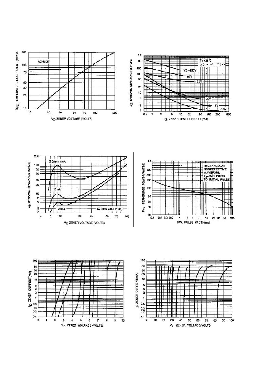
RATING AND CHARACTERISTICS CURVES
1SMB5926 THRU 1SMB5956
Fig. 1-STEADY STATE POWER DERATING Fig. 2-ZENER VOLTAGE TO 12 VOLTS