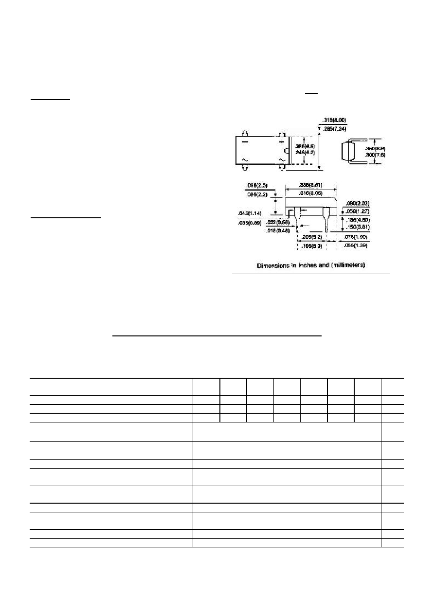
DI100/150 THRU DI1010/1510
DUAL-IN-LINE GLASS PASSIVATED SINGLE-PHASE BRIDGE RECTIFIER
VOLTAGE - 50 to 1000 Volts CURRENT - 1.0~1.5 Amperes
FEATURES
l
Plastic material used carries Underwriters
Laboratory recognition 94V-O
l
Low leakage
l
Surge overload rating-- 30~50 amperes peak
l
Ideal for printed circuit board
l
Exceeds environmental standards of
MIL-S-19500/228
MECHANICAL DATA
Case: Reliable low cost construction utilizing molded
plastic technique results in inexpensive product
Terminals: Lead solderable per MIL-STD-202,
Method 208
Polarity: Polarity symbols molded or marking on body
Mounting Position: Any
Weight: 0.02 ounce, 0.4 gram
MAXIMUM RATINGS AND ELECTRICAL CHARACTERISTICS
Ratings at 25 ambient temperature unless otherwise specified.
Single phase, half wave, 60Hz, Resistive or inductive load.
For capacitive load, derate current by 20%.
DI100
DI150
DI101
DI151
DI102
DI152
DI104
DI154
DI106
DI156
DI108
DI158
DI1010
DI1510
UNITS
Maximum Recurrent Peak Reverse Voltage
50
100
200
400
600
800
1000
V
Maximum RMS Bridge input Voltage
35
70
140
280
420
560
700
V
Maximum DC Blocking Voltage
50
100
200
400
600
800
1000
V
DI100
1.0
Maximum Average Forward Current
T
A
=40
DI150
1.5
A
DI100
30.0
Peak Forward Surge Current, 8.3ms single
half sine-wave superimposed on rated load
DI150
50.0
A
I
2
t Rating for fusing ( t < 8.35 ms)
10.0
A
2
t
Maximum Forward Voltage Drop per Bridge
Element at 1.0A
1.1
V
Maximum Reverse Current at Rated T
J
= 25
DC Blocking Voltage per element T
J
=125
5.0
0.5
A
mA
Typical Junction capacitance per leg (Note 1) CJ
25.0
P
F
Typical Thermal resistance per leg (Note 2) R JA
Typical Thermal resistance per leg (Note 2) R JL
40.0
15.0
/W
Operating Temperature Range T
J
-55 to +125
Storage Temperature Range T
A
-55 to +150
DIP

NOTES:
1. Measured at 1.0 MHz and applied reverse voltage of 4.0 Volts
2. Thermal resistance from junction to ambient and from junction to lead mounted on P.C.B. with
0.5
◊
0.5"(13
◊
13mm) copper pads
RATING AND CHARACTERISTIC CURVES
DI100/150 THRU DI1010/1510
Fig. 1-MAXIMUM NON-REPETITIVE SURGE CURRENT Fig. 2-DERATING CURVE FOR OUTPUT RECTIFIED
CURRENT
Fig. 3-TYPICAL FORWARD CHARACTERISTICS Fig. 4-TYPICAL REVERSE CHARACTERISTICS