GL1500, 2500, 3500 SERIES
IN-LINE HIGH CURRENT SILICON BRIDGE RECTIFIERS
VOLTAGE - 50 to 800 Volts CURRENT - 15 to 35 Amperes
FEATURES
l
Plastic Case With Heatsink For
Heat Dissipation
l
Surge Overload Ratings to 400
Amperes
l
The plastic package has Underwriters
Laboratory Flammability Classification
94V-O
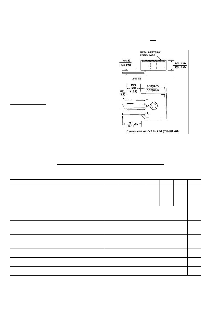
MECHANICAL DATA
Case: Molded plastic with heatsink
integrally mounted in the bridge
Encapsulation
Weight: 1 ounce, 30 grams
Mounting position: Any
Terminals: Wire Lead 50 mils
MAXIMUM RATINGS AND ELECTRICAL CHARACTERISTICS
Inductive or resistive Load at 60Hz. For capacitive load derate current by 20%.
All Ratings are for T
C
=25 unless otherwise specified.
-00
-01
-02
-04
-06
-08 UNITS
Max Recurrent Peak Reverse Voltage
50
100
200
400
600
800
V
Max RMS Input Voltage
35
70
140
280
420
560
V
Max DC Blocking Voltage
50
100
200
400
600
800
V
DC Output Voltage, Resistive Load
30
62
124
250
380
505
V
DC Output Voltage, Capacitive Load
50
100
200
400
600
800
V
GL15
15
A
GL25
25
A
Max Average Forward Current
for Resistive Load
at TC=55
GL35
35
A
GL15
300
A
GL25
300
A
Non-repetitive
Peak Forward Surge Current at
Rated Load
GL35
400
A
GL15 I
F
7.5A
GL25 12.5A
1.2
V
Max Forward Voltage
per Bridge Element at
Specified Current
GL35 17.5A
Max Reverse Leakage Current @ TA=25
at Rated DC Blocking Voltage @ TA=100
10
1000
A
I
2
t Rating for fusing ( t < 8.3ms )
374 / 664
A
2
s
Typical Thermal Resistance (Fig. 3) R JC
2.0
/W
Operating Temperature Range T
J
Storage Temperature Range T
A
-55 to +150
GL

RATING AND CHARACTERISTIC CURVES
GL1500 THRU GL3500
Fig. 1-TYPICAL INSTANTANEOUS FORWARD Fig. 2-OUTPUT CURRENT VS. CASE TEMPERATURE
CHARACTERISTICS AT T
J
=25 RESISTIVE OR INDUCTIVE LOAD T
J
=175
Fig. 3-OUTPUT CURRENT VS. AMBIENT Fig. 4-POWER DISSIPATION VS. AVERAGE OUTPUT
TEMPERATURE RESISTIVE OR CURRENT RESISTIVE OR INDUCTIVE LOAD,
INDUCTIVE LOAD BRIDGE MOUNTED T
J
=175
ON A8"
◊
8" ALUMINUM PLATE 25" THICK