- 526 -
SB 15, 25, 35G SERIES
High Current 15, 25, 35 AMPS. Single Phase Glass Passivated Bridge Rectifiers
Voltage Range
50 to 1000 Volts
Current
15.0/25.0/35.0 Amperes
Features
a
UL Recognized File # E-96005
a
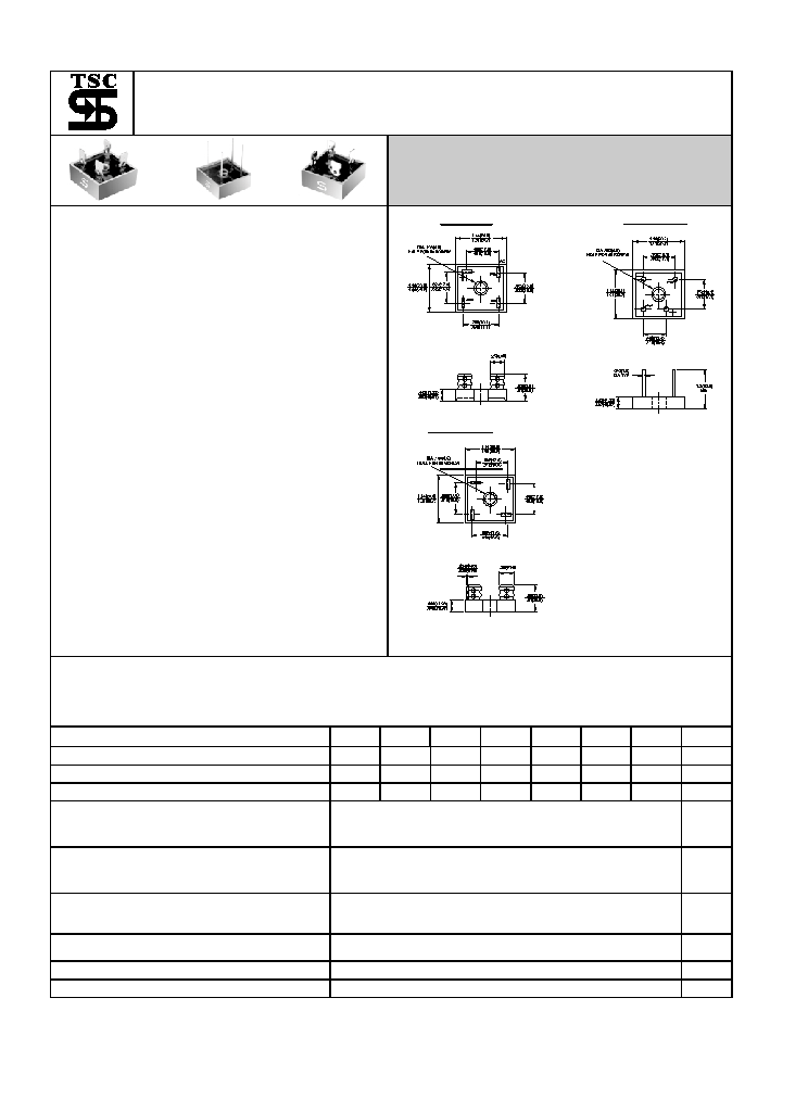
Metal case with an electrically isolated
epoxy
a
Rating to 1,000V PRV.
a
High
efficiency
a
Mounting: thru hole for #8 screw
a
High temperature soldering guaranteed:
260�C / 10 seconds at 5 lbs., ( 2.3 kg )
tension
a
Leads
solderable
per
MIL-STD-202
Method 208
a
Isolated voltage from case to lead over
2000 volts
SB35 SB35-W
SB-35M
Dimensions in inches and (millimeters)
Maximum Ratings and Electrical Characteristics
Rating at 25�C
ambient temperature unless otherwise specified.
Single phase, half wave, 60 Hz, resistive or inductive load.
For capacitive load, derate current by 20%
Type Number
-05
-1
-2
-4
-6
-8
-10
Units
Maximum Recurrent Peak Reverse Voltage
50
100
200
400
600
800
1000
V
Maximum RMS Voltage
35
70
140
280
420
560
700
V
Maximum DC Blocking Voltage
50
100
200
400
600
800
1000
V
Maximum Average Forward
Rectified Current
@T
C
= 55
�C
SB15
SB25
SB35
15.0
25.0
35.0
A
Peak Forward Surge Current,
Single Sine-wave Superimposed on
Rated Load (JEDEC method )
SB15
SB25
SB35
200
300
400
A
Maximum Instantaneous Forward
Voltage Drop Per Element
at Specified Current
SB15 7.5A
SB25 12.5A
SB35 17.5A
1.1
V
Maximum DC Reverse Current
at Rated DC Blocking Voltage Per Element
10
uA
Typical Thermal Resistance (Note 1) R
�
JC
2.0
�C/W
Operating and Storage Temperature Range T
J
,T
STG
-50 to +150 �C
Notes: 1. Thermal Resistance from Junction to Case.
Notes:
2. Suffix "W" - Wire Lead Structure/"M" - Terminal Location Face to Face.
- 527-
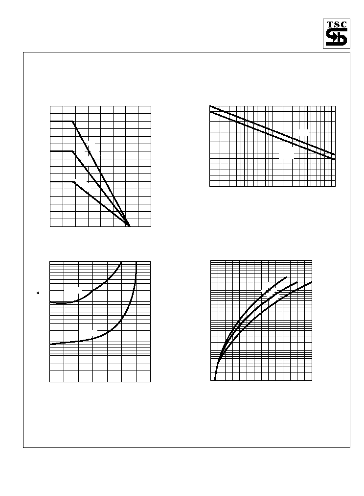
RATINGS AND CHARACTERISTIC CURVES (SB2505G THRU SB2510G)
FIG.3- TYPICAL REVERSE CHARACTERISTICS
PER BRIDGE ELEMENT
INST
ANT
ANEOUS
REVERSE
CURRENT
.(
A
)
0
20
40
60
80
100
120
140
0.1
1.0
10
100
PERCENT OF RATED PEAK REVERSE VOLTAGE. (%)
Tj=25 C
0
Tj=125 C
0
SB3505G
SB1505G
SB3510G
SB1510G
FIG.1- MAXIMUM FORWARD CURRENT
DERATING CURVE
A
VERAGE
FOR
W
ARD
CURRENT
.
(A)
160
180
20
40
60
80
100
120
140
0
5
10
15
20
25
40
35
30
CASE TEMPERATURE. ( C)
o
SB35G
SB
25G
SB15G
FIG.4- TYPICAL FORWARD CHARACTERISTICS
INST
ANT
ANEOUS
FOR
W
ARD
CURRENT
.
(A)
.6
.8
1.0
1.2
1.4
1.6
1.8
2.0
0.1
1.0
10
100
1000
FORWARD VOLTAGE. (V)
SB35G
SB15G
SB25G
FIG.2- MAXIMUM NON-REPETITIVE FORWARD
SURGE CURRENT PER BRIDGE ELEMENT
PEAK
FOR
W
ARD
SURGE
CURRENT
.
(A)
1
2
3
4
1.5
5 6
9
8
7
10
25
20
15
30
100
60
40
80
20
100
300
400
200
NUMBER OF CYCLES AT 60Hz
SB35G
SB15G
SB25G