- 92 -
REV.1 Oct.-2003
SR2020PT THRU SR2060PT
20.0 AMPS. Schottky Barrier Rectifiers
Voltage Range
20 to 60 Volts
Current
20.0 Amperes
Features
a
Dual rectifier construction, positive center-tap
a
Plastic package has Underwriters Laboratory Flammability
Classifications 94V-0
a
Metal silicon junction, majority carrier conduction
a
Low power loss, high efficiency
a
High current capability, low VF
a
High surge capability
a
Epitaxial construction
a
For use in low voltage, high frequency inverters, free
wheeling, and polarity protection applications
a
Guardring for transient protection
a
High temperature soldering guaranteed:
260
o
C/10seconds,0.17"(4.3mm)lead lengths at 5 lbs.,
(2.3kg) tension
Mechanical Data
a
Cases: JEDEC TO-3P/TO-247AD molded plastic
a
Terminals: Leads solderable per MIL-STD-750, Method 2026
a
Polarity: As marked
a
Mounting position: Any
a
Weight: 0.2 ounce, 5.6 grams
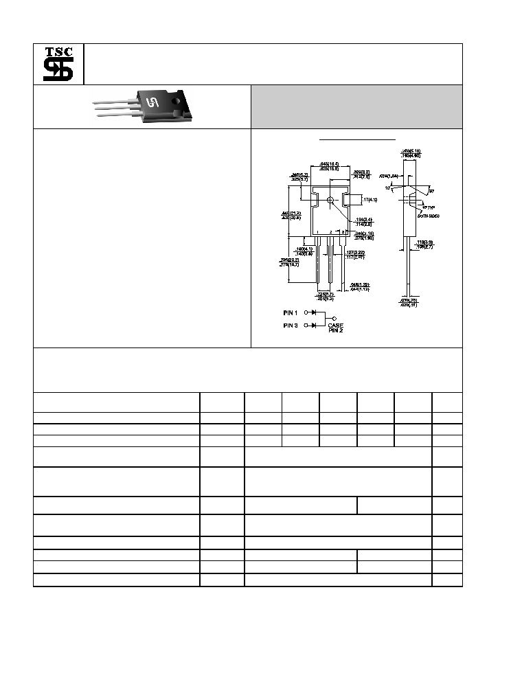
TO-3P/TO-247AD
Dimensions in inches and (millimeters)
Maximum Ratings and Electrical Characteristics
Rating at 25
+
ambient temperature unless otherwise specified.
Single phase, half wave, 60 Hz, resistive or inductive load.
For capacitive load, derate current by 20%
Type Number
Symbol
SR
2020PT
SR
2030PT
SR
2040PT
SR
2050PT
SR
2060PT
Units
Maximum Recurrent Peak Reverse Voltage
V
RRM
20 30 40 50 60 V
Maximum RMS Voltage
V
RMS
14 21 28 35 42 V
Maximum DC Blocking Voltage
V
DC
20 30 40 50 60 V
Maximum Average Forward Rectified
Current at Tc=105
+
I
(AV)
20
A
Peak Forward Surge Current, 8.3 ms Single
Half Sine-wave Superimposed on Rated
Load (JEDEC method )
I
FSM
250
A
Maximum Instantaneous Forward Voltage @10.0A
(Note 3)
V
F
0.55
0.70
V
Maximum D.C. Reverse Current @ Tc=25
+
at Rated
DC
Blocking Voltage @ Tc=100
+
I
R
1.0
50
mA
mA
Typical Thermal Resistance Per Leg (Note 1)
R
JC
1.5
+
/W
Typical Junction Capacitance (Note 2)
Cj 600
400
pF
Operating Junction Temperature Range
T
J
-65 to +125
-65 to +150
+
Storage Temperature Range
T
STG
-65 to +150
+
Notes:
1
.
Thermal Resistance from Junction to Case Per Leg.
2. Measured at 1 MHz and Applied Reverse Voltage of 4.0V D.C.
3. 300 us Pulse Width, 2% Duty Cycle
- 93 -
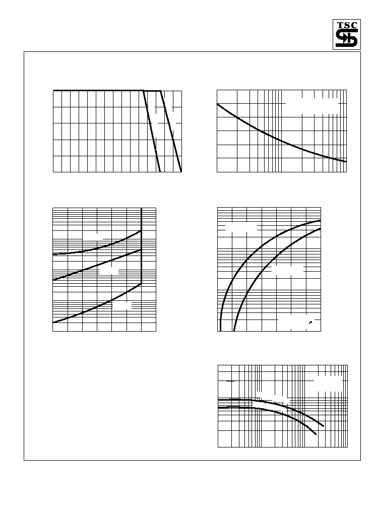
RATINGS AND CHARACTERISTIC CURVES (SR2020PT THRU SR2060PT)
FIG.2- MAXIMUM NON-REPETITIVE FORWARD
SURGE CURRENT PER LEG
PEAK
FOR
W
ARD
SURGE
CURRENT
.
(A)
1
2
5
10
20
100
50
100
50
200
150
250
300
NUMBER OF CYCLES AT 60Hz
8.3ms Single Half Sine Wave
PER LEG. (JEDEC Method)
Tj=Tj max.
FIG.4- TYPICAL FORWARD CHARACTERISTICS
INST
ANT
ANEOUS
FOR
W
ARD
CURRENT
.
(A)
.2
.3
.4
.5
.6
.7
.8
.9
0.1
1.0
10
100
INSTANTANEOUS FORWARD VOLTAGE. (V)
Tj=25 C
Pulse Width=300 s
2% Duty Cycle
o
SR2050PT THRU
SR2060PT
SR2020PT THRU
SR2040PT
FIG.3- TYPICAL REVERSE CHARACTERISTICS
PER LEG
INST
ANT
ANEOUS
REVERSE
CURRENT
MILLIAMPERES
0
20
40
60
80
100
120
140
.01
.10
1.0
10
100
PERCENT OF RATED PEAK REVERSE VOLTAGE. (%)
Tj=100 C
0
Tj=25 C
0
Tj=75 C
0
FIG.1- MAXIMUM FORWARD CURRENT DERATING
CURVE
A
VERAGE
FOR
W
ARD
CURRENT
.
(A)
0
50
100
150
0
4.0
8.0
12.0
16.0
20.0
CASE TEMPERATURE. ( C)
o
SR2050PT-2060PT
SR2020PT-2040PT
FIG.5- TYPICAL JUNCTION CAPACITANCE PER LEG
CAP
ACIT
ANCE.(pF)
.1
.4
1.0
4
10
40
100
100
200
400
600
1000
800
2000
4000
REVERSE VOLTAGE. (V)
Tj=25 C
f=1.0MHz
Vsig=50mVp-p
0
SR2050PT-2060PT
SR2020PT-2040PT