
GaAlAs T-1 PACKAGE
INFRARED EMITTING DIODE
MIE-304H4
Description
Package Dimensions
The MIE-304H4 is a GaAlAs infrared LED having a
peak wavelength at 850nm molded in water clear
plastic package. The forward voltage at low current
and at high pulse current roughly correspond to the
low values of the standard technology.
Features
l
Ultra-high radiant intensity
l
High response speed
l
Standard T-1 (
3mm ) package, radiant angle : 25∞
l
Peak wavelength
p
= 850 nm
Absolute Maximum Ratings
@ T
A
=25
o
C
Parameter
Maximum Rating
Unit
Power Dissipation
120
mW
Peak Forward Current
1
A
Continuous Forward Current
100
mA
Reverse Voltage
5
V
Operating Temperature Range
Storage Temperature Range
Lead Soldering Temperature
02/04/2002
260
o
C for 5 seconds
-55
o
C to +100
o
C
-55
o
C to +100
o
C
Unity Opto Technology Co., Ltd.
Unit : mm (inches )
Notes :
1. Tolerance is ± 0.25 mm (.010") unless otherwise noted.
2. Protruded resin under flange is 0.5 mm (.019") max.
3. Lead spacing is measured where the leads emerge from the package.
A
C
2.54NOM.
(.100)
0.50
(.020)
0.50 TYP.
(.020)
0.80
(.032)
3.00
(.118)
1.00 MIN.
(.039)
FLAT DENOTES CATHODE
4.00
(.158)
23.40MIN.
(.921)
5.40
(.213)
SEE NOTE 2
SEE NOTE 3
MIE-304H4
Optical-Electrical Characteristics
@ T
A
=25
o
C
Parameter
Test Conditions
Symbol
Min.
Typ .
Max.
Unit
Radiant Intensity
I
F
=20mA
Ie
-
3.5
-
mW/sr
Forward Voltage
I
F
=50mA
V
F
-
1.5
1.8
V
Reverse Current
V
R
=5V
I
R
-
-
100
µ
A
Peak Wavelength
I
F
=20mA
p
-
850
-
nm
Spectral Bandwidth
I
F
=20mA
-
30
-
nm
View Angle
I
F
=20mA
2
1/2
-
25
-
deg .
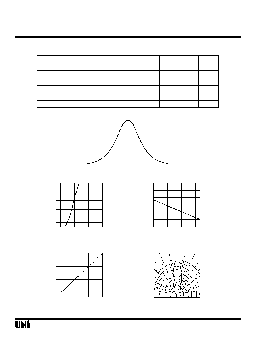
Typical Optical-Electrical Characteristic Curves
02/04/2002
Unity Opto Technology Co., Ltd.
0
0.5
1
750
850
950
0.0
0.5
1.0
1.5
2.0
2.5
3.0
-40
-20
0
20
40
60
Ambient Temperature T
A
(
o
C)
FIG.3 RELATIVE RADIANT INTENSITY
VS. AMBIENT TEMPERATURE
Output Power To Value I
F
=20mA
0
20
40
60
80
100
0.8
1.2
1.6
2.0
2.4
2.8
Forward Voltage (V)
FIG.2 FORWARD CURRENT VS.
FORWARD VOLTAGE
Forward Current (mA)
0
1
2
3
4
5
0
20
40
60
80
100
Forward Current (mA)
FIG.4 RELATIVE RADIANT INTENSITY
VS. FORWARD CURRENT
Output Power Relative To
Value at I
F
=20mA
Wavelength (nm)
FIG.1 SPECTRAL DISTRIBUTION
Relative Radiant Intensity
FIG.5 RADIATION DIAGRAM
0.5
0.3
0.1
0.2
0.4
0.6
30∞
40∞
90∞
70∞
60∞
50∞
80
1.0
0.9
0.8
Relative Radiant Intensity
0∞ 10∞ 20∞