T-1 3/4 (5mm) High
Performance AlInGaP LED Lamps
MVL-5A4UG
Description
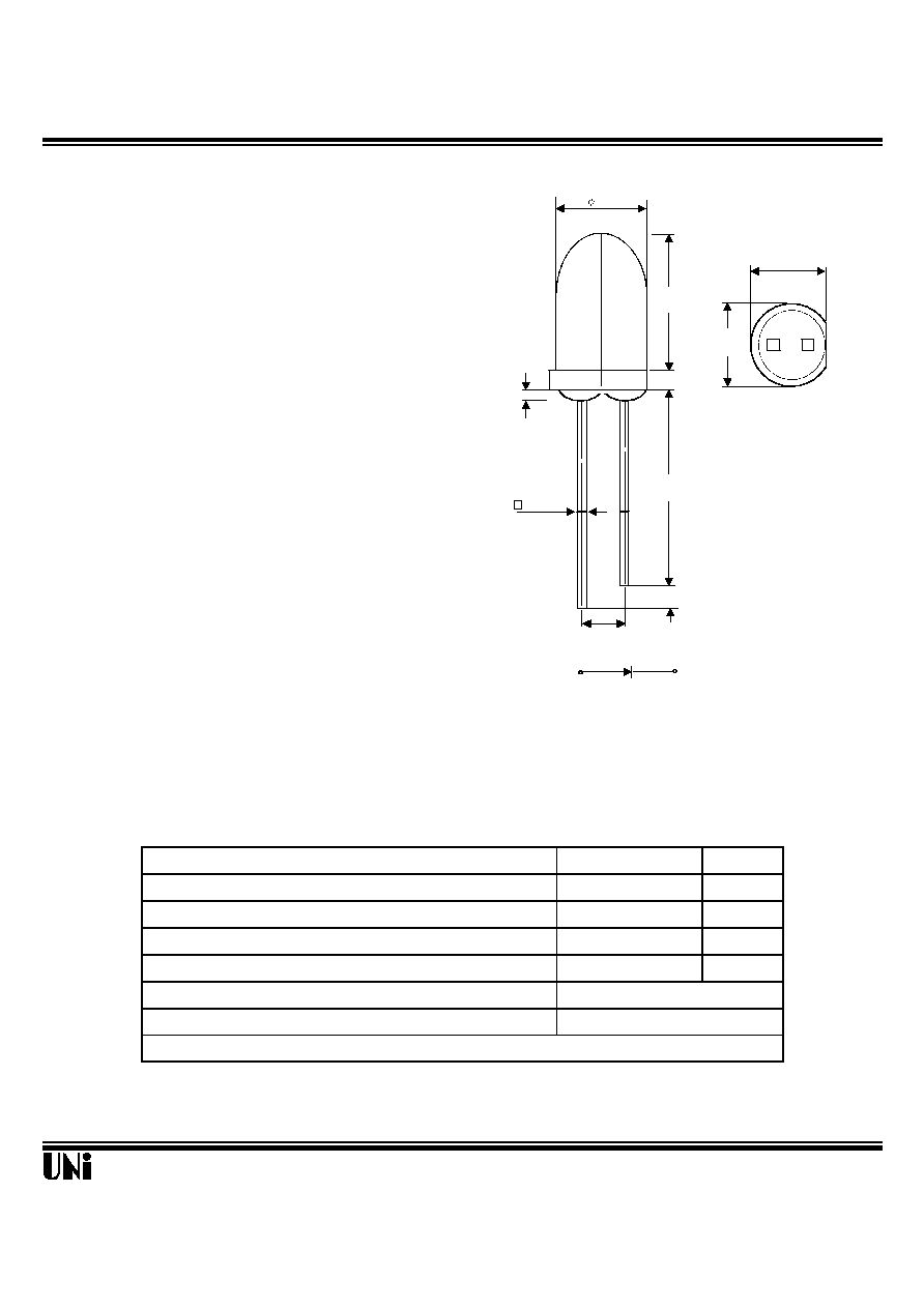
Package Dimensions
The MVL-5A4UG , utilizes the latest absorbing
subsstrate aluminum indium gallium phosphide
(AlInGaP) LED technology. This LED material
has outstanding light output efficiency over
a wide range of drive current.
The package is T-1 3/4(5mm) water clear standard type.
Features
l
Standard T-1 3/4 (
5mm) package
l
Low power consumption
l
High efficiency
l
Reliable
Absolute Maximum Ratings
@ T
A
=25
o
C
Parameter
Maximum Rating
Unit
Power Dissipation
125
mW
Peak Forward Current(1/10 Duty Cycle100
µ
s pulse width )
100
mA
Continuous Forward Current
50
mA
Reverse Voltage
5
V
Operating Temperature Range
-40
o
C
to +100
o
C
Storage Temperature Range
-40
o
C
to +100
o
C
01/09/2002
Lead Soldering Temperature 1.6 mm from body for 5 seconds at 260
o
C
Unity Opto Technology Co., Ltd.
Notes :
1. Tolerance is ± 0.25 mm (.010") unless otherwise noted.
2. Protruded resin under flange is 1.5 mm (.059") max.
3. Lead spacing is measured where the leads emerge from the package.
7.62
(.300)
5.05
(.200)
1.00
(.040)
5.90
(.230)
2.54TYP.
(.1)
0.50 TYP.
(.020)
25.40 MIN.
(1.000)
1.00MIN.
(.040)
5.47
(.215)
SEE NOTE 3
A
C
Unit: mm ( inches )
2.54TYP.
(.100)
SEE NOTE 2
MVL-5A4UG
Optical-Electrical Characteristics
@ T
A
=25
o
C
Parameter
Test Conditions
Symbol
Min .
Typ .
Max .
Unit .
Luminous Intensity
I
F
=20mA
I
V
1500
3000
-
mcd
Forward Voltage
I
F
=20mA
V
F
-
2.0
2.6
V
Reverse Current
V
R
=5V
I
R
-
-
100
µ
A
Dominant Wavelength
I
F
=20mA
d
-
572
-
nm
Spectral Line Half Width
I
F
=20mA
-
15
-
nm
Viewing Angle
I
F
=20mA
2
1/2
-
8
-
deg.
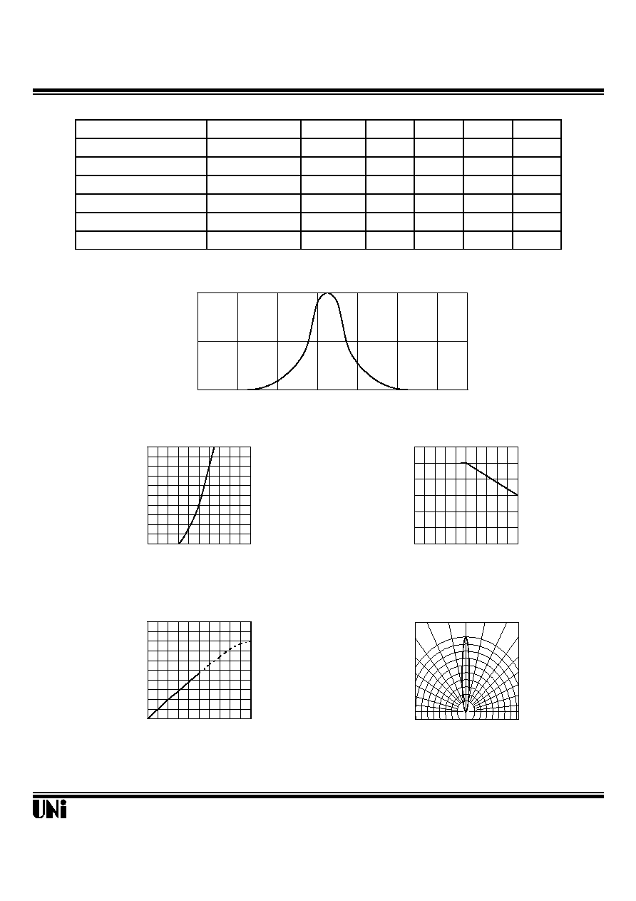
Typical Optical-Electrical Characteristic Curves
01/09/2002
Unity Opto Technology Co., Ltd.
0
0.5
1
510
530
550
570
590
610
630
Relative Luminous
Intensity
Wavelength (nm)
FIG.1 SPECTRAL DISTRIBUTION
0
10
20
30
40
50
60
0
20
40
60
80 100
0
5
10
15
20
25
30
35
40
45
50
1.2 1.6 2.0 2.4 2.8 3.2
Ambient Temperature T
A
(
o
C
)
FIG.3 FORWARD CURRENT
VS. AMBIENT TEMPERATURE
0.0
1.0
2.0
3.0
4.0
5.0
0
20
40
60
80 100
Forward Current (mA)
FIG.4 RELATIVE LUMINOUS INTENSITY
VS. FORWARD CURRENT
Forward Current I
F
(mA)
Forward Current I
F
(mA)
Forward VoltageV
F
(V)
FIG.2 FORWARD CURRENT
VS. FORWARD VOLTAGE
1.0
0.9
0.8
FIG.5 RADIATION DIAGRAM
0
∞
10
∞
20
∞
Relative Luminous Intensity
Relative Luminous Intensity
30
o
40
o
50
o
60
o
70
o
80
o
90
o
0.5 0.3 0.1 0.2 0.4 0.6