page
1
phone: 360.260.2468
l
sales: 800.736.0194
l
fax: 360.260.2469
email: sales@usdigital.com
l
website: www.usdigital.com
11100 ne 34th circle
l
vancouver, washington 98682 USA
AD5
Four Quadrature Encoders to SEI Adapter
Adapter
US
Digital
C o r p o r a t i o n
TM
Ordering Information:
Technical Data, Rev. 04.02.03, April 2003
All information subject to change without notice.
Price:
$195 / 1
$175 / 10
$165 / 50
$155 / 100
$145 / 500
$135 / 1K
Cost Modifiers:
Add $15 for D-interface.
Add $10 for R-option.
Subtract $5 for NP-option.
Includes:
ÿ
PS-9V (power supply).
ÿ
USD-SW (software).
AD5 -
Part #:
Options:
R = DIN rail (35mm wide) mounting.
NP = No power supply (PS-9V).
Interface:
S = 5-pin single-ended.
S6 = 6-pin single-ended.
D = 10-pin differential.
Parameter
Min.
Max.
Units
Storage Temperature
-40
70
∞C
Operating Temperature
0
70
∞C
Humidity (non-condensing)
0
95
%
ÿ
ESD warning: Normal handling precautions should be taken to avoid
static discharge.
Absolute Maximum Ratings:
The software includes a demo/configuration utility which detects encoders on the
network and displays their position on the screen. The SEI software recognizes
encoders on the bus, automatically assigning them unique addresses. The utility
includes diagnostics which display status, assigned address, serial number, model,
and version of each encoder, verifying that the SEI bus is operating correctly. It also
allows the user to change the resolution, address, mode and zero position of each
encoder. The SEI software has the ability to record positions to file. The format is
Windows 95/98/ME, Windows NT/2000/XP compatible software on a CD-ROM. A
"readme" file contains additional information.
SEI Software:
Part# USD-SW (Included with every order.)
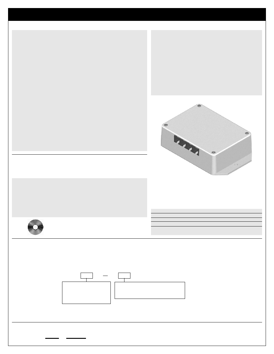
The AD5 quadrature encoder to SEI adapter is a simple, quick and convenient way
of interfacing up to four incremental encoders to US Digital's SEI bus, which can easily
be interfaced to an RS232 Port. The AD5 is available in single-ended finger-latching,
single-ended modular, and differential finger-latching. The AD5 connects to the SEI
bus and simultaneously tracks up to four incremental encoders (see the SEI data
sheet). DIN rail mounting is available.
The AD5 is powered by the SEI bus or by a separate power supply. It then supplies
power to the incremental encoders which are attached. The AD5 retains configuration
settings when power is removed, but not count values. If power is lost, the counters
reset to zero and a home cycle is needed. Providing an uninterruptable power source
to the AD5 by inserting an SEI-UPS in line, with the SEI cable feeding the AD5 solves
this issue (see the SEI-UPS data sheet).
The AD5 supports both indexed and non-indexed encoders in QUAD1, QUAD2,
QUAD4, or Non-Quadrature modes. It provides independent, bidirectional counts from
each of its four ports. From -8,388,608 to 8,388,607 at rates of up to 2MHz in non-
quadrature mode, and 230 KHz in quadrature mode. It provides count modes of Normal
Count, Modulo-N, and Range Limit.
US Digital offers three SEI interfaces: the AD2-B adapter for interface to a standard
9-pin RS232 port, the AD2-A adapter for interface to a 25-pin RS232 port, and the USB1
encoder interface for a USB port. One of these products is required in order to interface
the A2 to a PC via our SEI bus. The wall-mount PS-9V power supply furnishes the
power for all devices on the SEI bus (see each product's data sheet).
Note: The encoder interface IC used in this product can be purchased separately.
More detailed information can be found on the LS7266R1 data sheet.
Description:
ÿ
Four ports allow simultaneous reading of up to 4 incremental
encoders
ÿ
Each port independently configurable
ÿ
DIN rail mounting is available
ÿ
All features accessible using simple commands over the SEI bus
ÿ
Count speeds up to 2 MHz (230KHz in quadrature mode)
ÿ
Quadrature sensing (up to 4 times resolution)
ÿ
Digital filtering of quadrature signals
ÿ
Retains configuration settings when power is removed
ÿ
Uses standard PC data rates up to 115 Kbaud
ÿ
-0∞ to 70∞C operating temperature
ÿ
Host software and C source code available
ÿ
Rugged, simple, low cost
ÿ
US Digital warrants its products against defects in materials and
workmanship for two years. See complete warranty for details.
Features:
page
2
phone: 360.260.2468
l
sales: 800.736.0194
l
fax: 360.260.2469
email: sales@usdigital.com
l
website: www.usdigital.com
11100 ne 34th circle
l
vancouver, washington 98682 USA
AD5
Four Quadrature Encoders to SEI Adapter
Adapter
US
Digital
C o r p o r a t i o n
TM
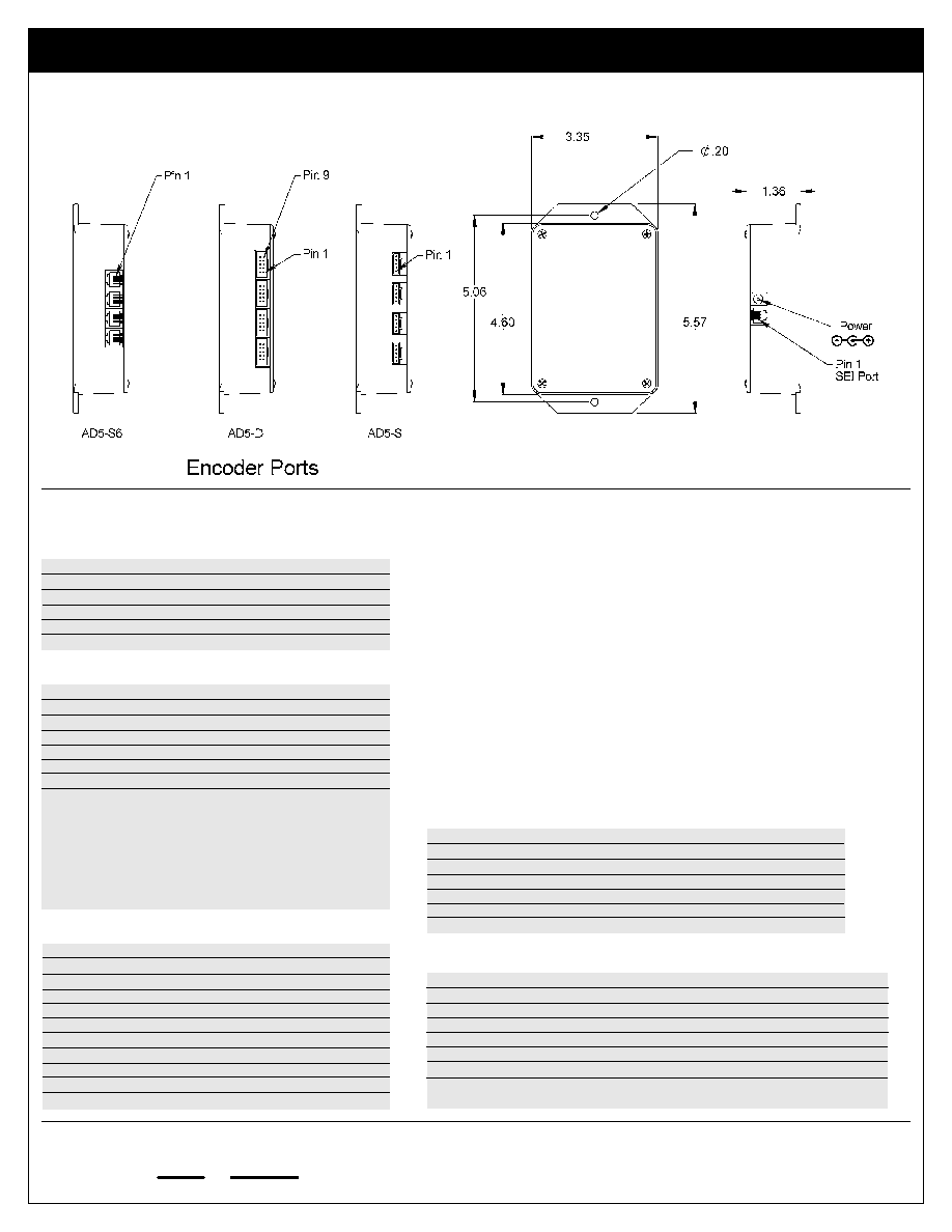
Mechanical Specifications:
Encoder Port (6-pin Modular):
Pin
Name
Description
1
GND
Ground, common for power and data
2
I
Index input, high = true
3
A
Quadrature input
4
PWR
Power supply output to encoder
5
B
Quadrature input
Encoder Port (5-pin Finger-latching):
Parameter
Min.
Typ.
Max.
Units
Supply Voltage (PWR)
9.0
-
16
Volts
Supply Current (no encoders)
-
21
60
mA
A+, B+, I+ Encoder Inputs Low
-
-
1.6
Volts
A+, B+, I+ Encoder Inputs High
3.2
-
-
Volts
Output Voltage to Encoders
4.9
5.0
5.1
Volts
Output Current to All Encoders
-
-
340
mA
ÿ
Specifications apply over entire operating temperature range.
ÿ
Typical values are specified at Vcc=12V and 25∞C.
Electrical Characteristics:
Pin
Name
Description
1
GND
Ground, common for power, data and busy pairs
2
Busy+
Bidirectional differential acknowledge line
3
Busy-
Bidirectional differential acknowledge line
4
PWR
Power supply input
5
DataL
Bidirectional differential data line
6
DataH
Bidirectional differential data line
SEI Port:
Encoder Port (10-pin Finger-latching):
Pin
Name
Description
1
GND
Ground, common for power and data
2
GND
Ground, common for power and data
3
I-
Index input, high = true
4
I+
Index input, high = true
5
A-
Quadrature input
6
A+
Quadrature input
7
PWR
Power supply output to encoder
8
PWR
Power supply output to encoder
9
B-
Quadrature input
10
B+
Quadrature input
Pin
Name
Description
1
I
Index input, high = true
2
GND
Ground, common for power and data
3
A
Quadrature input
4
PWR
Power supply output to encoder
5
B
Quadrature input
6
GND
Ground, common for power and data
Notes:
ÿ
The power output to the encoder is +5V regulated from the
power input (PWR). When using long cables, consider the
voltage drop due to the current consumption of the encoder. If
a long cable is required then use either a low gauge cable or an
additional power supply next to the encoders.
ÿ
All inputs have 2.2 KOhm pullups to +5V and 51 Ohm resistors
in series with diodes to reduce reflection.