page
1
phone: 360.260.2468
l
sales: 800.736.0194
l
fax: 360.260.2469
email: sales@usdigital.com
l
website: www.usdigital.com
11100 ne 34th circle
l
vancouver, washington 98682 USA
S4
Miniature Optical Shaft Encoder
US
Digital
C o r p o r a t i o n
TM
Description:
The S4 miniature optical shaft encoder is a non-contacting rotary to digital
converter. Useful for position feedback or manual interface, the encoder converts
real-time shaft angle, speed, and direction into TTL-compatible quadrature outputs
without index. The encoder utilizes an unbreakable mylar disk, metal shaft, and
bushing or bearing. It operates from a single +5VDC supply.
The S4 encoder is available with ball bearings for motion control applications, or
static drag to feel like a potentiometer for front-panel manual interface.
The reflective sensor incorporates an LED light source and a monolithic photo
detector with signal shaping electronics, providing two channel bounceless
quadrature TTL outputs.
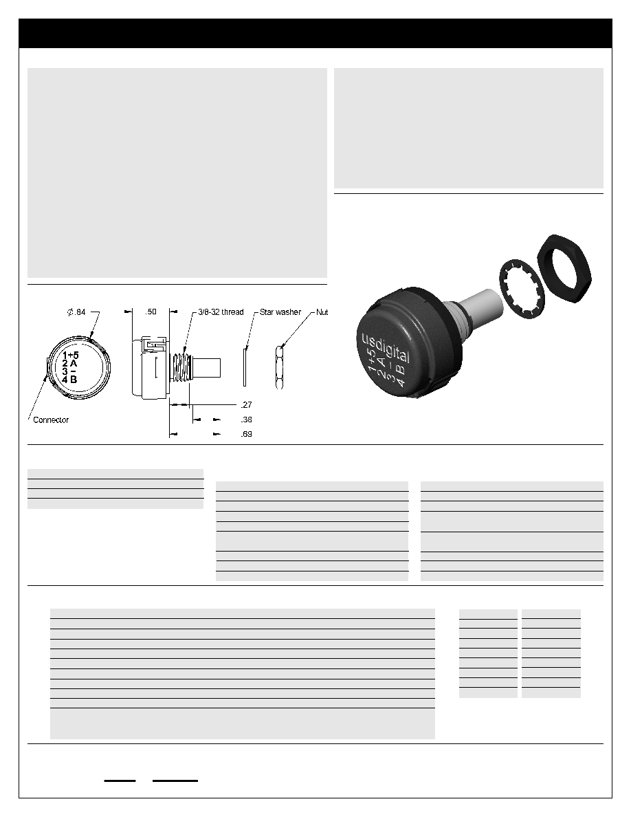
The S4 can be connected by using a high retention 4 conductor snap-in polarized
1.25mm pitch connector. The mating connector is polarized and should attach
smoothly to the encoder; do not force. See the next page of this data sheet for
Cables & Connectors.
Electrical Specifications:
B leads A for clockwise shaft rotation, A leads B for counter clockwise shaft
rotation viewed from the shaft/bushing side of the encoder.
ÿ
Miniature size
ÿ
Low cost
ÿ
High retention snap-in polarized connector
ÿ
Tracks from 0 to 30,000 cycles/sec
ÿ
Ball bearing option tracks up to 7,000 or 15,000 RPM
ÿ
-10 to +85∞C operating temperature
ÿ
120 to 300 cycles per revolution (CPR)
ÿ
480 to 1200 pulses per revolution (PPR)
ÿ
2 channel quadrature TTL squarewave outputs
ÿ
Low power strobe option available
ÿ
US Digital warrants its products against defects and workmanship
for two years. See complete warranty for details.
Sleeve Bushing Version
Mechanical Notes:
Acceleration
10,000 rad/sec
2
Vibration
20 g. 5 to 2KHz
Shaft Speed
100 RPM max. continuous
Shaft Torque
0.5 ±0.2 inch-oz.
0.3 inch-oz. max. (NT-option)
Shaft Loading
2 lbs. max. dynamic
20 lbs. max. static
Weight
0.46 oz.
Shaft Runout
0.0015 T.I.R. max.
Shaft Material
Stainless steel
Features:
Mechanical Specifications:
Parameter
Min.
Typ.
Max
Units
Notes
Supply Voltage (Vcc)
4.5
5.0
5.5
VDC
Ripple < 100mVp-p. See note 1.
Supply Current
15
21
29
mA
See note 3.
Load Capacitance
-
-
100
pF
See note 2.
Count Frequency
-
-
30
kHzRPM/60 x cycles/rev.
High Level Output Voltage
2.4
-
Vcc
VDC
I
OH
= -640 µA max. See note 2.
Low Level Output Voltage
-
-
0.4
VDC
I
OL
= 3.86 mA
Rise Time
-
150
200
ns
25pF. See note 2.
Fall Time
-
50
60
ns
Operational Temperature
-10∞C
-
85∞C
-
Note 1: Standard internal .1uF bypass capacitor is installed between power and ground.
Note 2: Standard internal 3.3KOhm pull-ups are installed on channels A and B.
Note 3: For low power strobe mode see next page.
Electrical Specifications:
Materials & Mounting:
Bushing
Brass
Hole Diameter
0.375" +.005 - 0
Panel Thickness
0.125 inches max.
Panel Nut Max Torque
20 inch-lbs.
Acceleration
250,000 rad/sec
2
Vibration
20 g. 5 to 2KHz
Shaft Speed
15,000 RPM max. continuous
Shaft Torque
0.05 inch-oz. max.
Shaft Loading
1 lb. max.
Bearing Life
(40/P)
3
= Life in millions of revs.
Where P = Radial load in pounds
Weight
0.42 oz.
Shaft Runout
0.0015 T.I.R. max.
Shaft Material
Brass
Ball Bearing Version
Mechanical Notes:
Mechanical
CPR
RPM
120
50000
125
50000
128
50000
250
50000
256
50000
288
50000
300
50000
Electrical
CPR
RPM
120
15000
125
15000
128
15000
250
7200
256
7200
288
6250
300
6000
Max Shaft Speed:

page
2
phone: 360.260.2468
l
sales: 800.736.0194
l
fax: 360.260.2469
email: sales@usdigital.com
l
website: www.usdigital.com
11100 ne 34th circle
l
vancouver, washington 98682 USA
S4
Miniature Optical Shaft Encoder
US
Digital
C o r p o r a t i o n
TM
Technical Data, Rev. 10.02.02, October 2002
All information subject to change without notice.
CPR (N): The number of Cycles Per Revolution.
One Shaft Rotation: 360 mechanical degrees, N cycles.
One Electrical Degree (∞e): 1/360 of one cycle.
One Cycle (C): 360 electrical degrees (∞e). Each cycle can be decoded
into 1 or 4 codes, referred to as X1 or X4 resolution multiplication.
Symmetry: A measure of the relationship between (X) and (Y) in
electrical degrees, nominally 180∞e.
Quadrature (Z): The phase lag or lead between channels A and B in
electrical degrees, nominally 90∞e.
Cycle Error: An indication of cycle uniformity. The difference between
an observed shaft angle which gives rise to one electrical cycle, and
the nominal angular increment of 1/N of a revolution.
Ordering Information:
S4 -
Options:
(specify in order shown)
L = Low power strobe.
B = Ball bearings (free spinning).
M6 = Metric 6mm diameter shaft.
8 = 1/8" diameter shaft.
NT = Light static drag.
CPR:
120
125
128
250
256
288
300
Compatible Cables & Connectors:
4-pin Micro:
CON-MIC4
Connector
CA-3285
Connector on one end with 4 12" wires
CA-3286
Connector on one end of a 6' round twisted pair cable
Note: See Cables & Connectors data sheet for more information.
Cost Modifiers:
ÿ
Add $6 for B-option.
ÿ
Add $5 for M6-option.
Price:
$39 / 1
$35 / 10
$32 / 50
$29 / 100
$26 / 500
$24 / 1K
Notes:
ÿ
When M6-option or 8-option are not
specified the default is .250" diameter shaft.
ÿ
When B-option or NT-option are not
specified the default is static drag, like a
potentiometer.
Low Power Strobe (L-option):
To reduce the average power requirements, the L-option version of the S4 power can be strobed on just long enough to sample
outputs A and B. This option is the same as our standard S4, except the internal power bypass capacitor is not installed. The
output settling time is typically 200 to 400 nano seconds after power up. The sample frequency must be greater than the maximum
RPM X the CPR / 10.
Encoding Characteristics:
Accuracy
Min.
Typ.
Max.
Units
Symmetry
130
180
230
∞e
Quadrature
15
90
165
∞e
Symmetry*
95
180
265
∞e
Quadrature*
5
90
175
∞e
Cycle Error
-90
0
+90
arc min.
* For resolutions <110 CPR.
Cables Notes:
ÿ
The connector built into the encoder is Molex# 53048-0410.
ÿ
Special crimp tool (Molex# 50079) is needed to install connector pins.
ÿ
The mating connector is made up of housing (Molex# 51021-0400) and
4 individual crimp-on pins (Molex# 50079-8100).
Internal Schematic:
Encoder Pin-out:
Pin
Description
1
+5VDC power
2
A channel
3
Ground
4
B channel