
� 2002 Ubicom, Inc. All rights reserved.
- 1 -
www.ubicom.com
UbicomTM and the Ubicom logo are trademarks of Ubicom, Inc.
I
2
CTM is a trademark of Philips Corporation.
All other trademarks mentioned in this document are property of their respec-
tive companies.
April, 2002
SX48BD/SX52BD
Configurable Communications Controllers with EE/Flash Program
Memory, In-System Programming Capability, and On-Chip Debug
1.0
PRODUCT OVERVIEW
1.1
Introduction
The Ubicom SX48BD/SX52BD are members of the SX
family of configurable communications controllers fabri-
cated in an advanced CMOS process technology. The
advanced process, combined with a RISC-based archi-
tecture, allows high-speed computation, flexible I/O con-
trol, and efficient data manipulation. Throughput is
enhanced by operating the device at frequencies up to 75
MHz and by optimizing the instruction set to include
mostly single-cycle instructions. In addition, the SX archi-
tecture is deterministic and totally reprogramable. The
unique combination of these characteristics enables the
device to implement hard real-time functions as software
modules (Virtual PeripheralTM) to replace traditional hard-
ware functions.
On-chip functions include two 16-bit timers with 8-bit
prescalers supporting different operating modes (PWM,
simultaneous PWM/capture, and external event counter),
a general-purpose 8-bit timer with prescaler, an analog
comparator, a brown-out detector, a watchdog timer, a
power-save mode with multi-source wakeup capability,
an internal R/C oscillator, user-selectable clock modes,
and high-current outputs.
The SX48BD and SX52BD are functionally the same,
except for the package type and pinout. The SX48BD
has four fewer pins and has only four rather than eight
I/O pins for Port A.
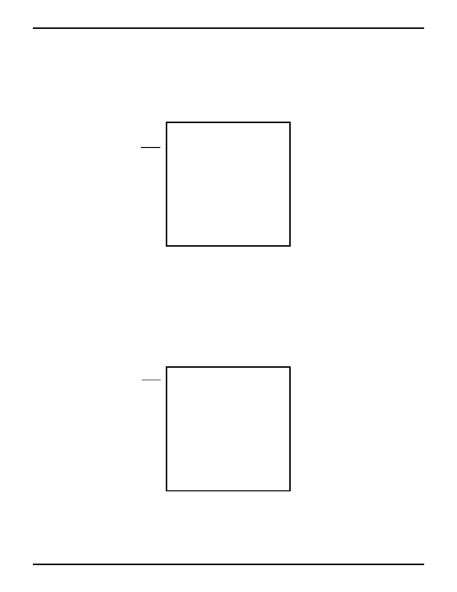
Figure 1-1. Block Diagram
Interrupt MIWU
Port B
COMPARATOR
Power-On
Reset
RESET
8-bit Watchdog
Timer (WDT)
8-bit Timer
RTCC
8
Internal Data Bus
System
Clock
Brown-Out
MIWU
MCLR
OSC Driver
4MHz Internal
RC OSC
(divided by
Clock
Select
System Clock
OSC1 OSC2
8
3
8 steps)
8-Bit
Prescaler
16-Bit
Timer 2
Port A
4/8
Port C Port D Port E
8
8
8
8
8
8
8
8
In-System
Debugging
In-System
Programming
4k Words
EEPROM
262 Bytes
SRAM
Address
Write Data
Read Data
Instruction
W
FSR
STATUS
PC
MODE
OPTION
Fetch
8
8
12
Address
12
8
8
8
8
ALU
8
8
8
PC
8 Level
Decode
Execute
Write Back
IREAD
Stack
Instruction
Pipeline
Interrupt
Stack
Prescaler for RTCC
Postscaler for WDT
or
Data
8-Bit
Prescaler
16-Bit
Timer 1
Port B
Port C
RTCC
WDT Clock
SLE
EP Cloc
k

� 2002 Ubicom, Inc. All rights reserved.
- 2 -
www.ubicom.com
SX48BD/SX52BD
Table of Contents
1.0
Product Overview . . . . . . . . . . . . . . . . . . . . . . . . . . . . . . . . . . 1
1.1
Introduction . . . . . . . . . . . . . . . . . . . . . . . . . . . . . . . 1
1.2
Key Features . . . . . . . . . . . . . . . . . . . . . . . . . . . . . . 3
1.3
Architecture . . . . . . . . . . . . . . . . . . . . . . . . . . . . . . . 4
1.3.1
The Virtual Peripheral Concept . . . . . . . . 4
1.3.2
The Communications Controller . . . . . . . 4
1.4
Programming and Debugging Support . . . . . . . . . . 4
1.5
Applications . . . . . . . . . . . . . . . . . . . . . . . . . . . . . . . 4
2.0
Connection Diagrams . . . . . . . . . . . . . . . . . . . . . . . . . . . . . . . 5
2.1
Pin Assignments . . . . . . . . . . . . . . . . . . . . . . . . . . . 5
2.2
Pin Descriptions . . . . . . . . . . . . . . . . . . . . . . . . . . . 6
2.3
Part Numbering . . . . . . . . . . . . . . . . . . . . . . . . . . . . 7
3.0
Port Descriptions . . . . . . . . . . . . . . . . . . . . . . . . . . . . . . . . . . 8
3.1
Reading and Writing the Ports . . . . . . . . . . . . . . . . . 8
3.2
Read-Modify-Write Considerations . . . . . . . . . . . . 11
3.3
Port Configuration . . . . . . . . . . . . . . . . . . . . . . . . . 11
3.3.1
MODE Register . . . . . . . . . . . . . . . . . . . 11
3.3.2
Port Configuration Registers . . . . . . . . . 13
3.3.3
Port Configuration Upon Power-Up . . . . 13
4.0
Special-Function Registers . . . . . . . . . . . . . . . . . . . . . . . . . 14
4.1
PC Register (02h) . . . . . . . . . . . . . . . . . . . . . . . . . 14
4.2
STATUS Register (03h) . . . . . . . . . . . . . . . . . . . . . 14
4.3
OPTION Register . . . . . . . . . . . . . . . . . . . . . . . . . . 15
4.4
DEVICE CONFIGURATION AND ID REGISTERS 15
4.5
FUSE Word (Read/Program via programming
command)
16
4.6
FUSEX Word (Read/Program via Programming
Command)
17
4.7
DEVICE ID Word (Hard-Wired Read-Only Via
Programming Command)- Part ID Code . . . . . . . . 17
4.8
User Code ID . . . . . . . . . . . . . . . . . . . . . . . . . . . . . 17
5.0
Memory Organization . . . . . . . . . . . . . . . . . . . . . . . . . . . . . . 18
5.1
Program Memory . . . . . . . . . . . . . . . . . . . . . . . . . . 18
5.1.1
Program Counter . . . . . . . . . . . . . . . . . . 18
5.1.2
Subroutine Stack . . . . . . . . . . . . . . . . . . 18
5.2
Data Memory . . . . . . . . . . . . . . . . . . . . . . . . . . . . . 18
5.2.1
Addressing Modes/FSR . . . . . . . . . . . . . 18
5.2.2
Register Access Examples . . . . . . . . . . 20
6.0
Power Down Mode . . . . . . . . . . . . . . . . . . . . . . . . . . . . . . . . 21
6.1
Multi-Input Wakeup . . . . . . . . . . . . . . . . . . . . . . . . 21
6.2
Port B MIWU/Interrupt Configuration . . . . . . . . . . . 22
7.0
Interrupt Support . . . . . . . . . . . . . . . . . . . . . . . . . . . . . . . . . 23
8.0
Oscillator Circuits . . . . . . . . . . . . . . . . . . . . . . . . . . . . . . . . . 25
8.1
XT, LP or HS modes . . . . . . . . . . . . . . . . . . . . . . . 25
8.2
External RC Mode . . . . . . . . . . . . . . . . . . . . . . . . . 25
8.3
Internal RC Mode . . . . . . . . . . . . . . . . . . . . . . . . . . 26
9.0
Real Time Clock/Counter (RTCC)/Watchdog Timer . . . . . . 27
9.1
RTCC . . . . . . . . . . . . . . . . . . . . . . . . . . . . . . . . . . . 27
9.2
Watchdog Timer . . . . . . . . . . . . . . . . . . . . . . . . . . . 27
9.3
The Prescaler . . . . . . . . . . . . . . . . . . . . . . . . . . . . . 27
10.0
Multi-Function Timers . . . . . . . . . . . . . . . . . . . . . . . . . . . . . .29
10.1
Timer Registers . . . . . . . . . . . . . . . . . . . . . . . . . . .29
10.2
Timer Operating Modes . . . . . . . . . . . . . . . . . . . . .30
10.2.1
PWM Mode . . . . . . . . . . . . . . . . . . . . . .30
10.2.2
Software Timer Mode . . . . . . . . . . . . . . .30
10.2.3
External Event Mode . . . . . . . . . . . . . . .30
10.2.4
Capture/Compare Mode . . . . . . . . . . . . .31
10.3
Timer Pin Assignments . . . . . . . . . . . . . . . . . . . . .31
10.4
Timer Control Registers . . . . . . . . . . . . . . . . . . . . .31
11.0
Comparator . . . . . . . . . . . . . . . . . . . . . . . . . . . . . . . . . . . . . .36
12.0
Reset . . . . . . . . . . . . . . . . . . . . . . . . . . . . . . . . . . . . . . . . . . . .38
13.0
Brown-Out Detector . . . . . . . . . . . . . . . . . . . . . . . . . . . . . . .39
14.0
Register States Upon Different Reset Conditions . . . . . . .40
15.0
Instruction Set . . . . . . . . . . . . . . . . . . . . . . . . . . . . . . . . . . . .41
15.1
Instruction Set Features . . . . . . . . . . . . . . . . . . . . .41
15.2
Instruction Execution . . . . . . . . . . . . . . . . . . . . . . .41
15.3
Addressing Modes . . . . . . . . . . . . . . . . . . . . . . . . .42
15.4
The Bank Instruction . . . . . . . . . . . . . . . . . . . . . . .42
15.5
Bit Manipulation . . . . . . . . . . . . . . . . . . . . . . . . . . .42
15.6
Input/Output Operation . . . . . . . . . . . . . . . . . . . . . .42
15.6.1
Read-Modify-Write Considerations . . . .42
15.7
Increment/Decrement . . . . . . . . . . . . . . . . . . . . . . .42
15.8
Loop Counting and Data Pointing Testing . . . . . . .42
15.9
Branch and Loop Call Instructions . . . . . . . . . . . . .43
15.9.1
Jump Operation . . . . . . . . . . . . . . . . . . .43
15.9.2
Page Jump Operation . . . . . . . . . . . . . .43
15.9.3
Call Operation . . . . . . . . . . . . . . . . . . . .43
15.9.4
Page Call Operation . . . . . . . . . . . . . . . .43
15.10
Return Instructions . . . . . . . . . . . . . . . . . . . . . . . . .43
15.11
Subroutine Operation . . . . . . . . . . . . . . . . . . . . . . .44
15.11.1
Push Operation . . . . . . . . . . . . . . . . . . .44
15.11.2
Pop Operation . . . . . . . . . . . . . . . . . . . .44
15.12
Comparison and Conditional Branch Instructions .45
15.13
Logical Instruction . . . . . . . . . . . . . . . . . . . . . . . . .45
15.14
Shift and Rotate Instructions . . . . . . . . . . . . . . . . .45
15.15
Complement and SWAP . . . . . . . . . . . . . . . . . . . .45
15.16
Key to Abbreviations and Symbols . . . . . . . . . . . . .45
16.0
Instruction Set Summary Table . . . . . . . . . . . . . . . . . . . . . .46
16.1
Equivalent Assembler Mnemonics . . . . . . . . . . . . .49
17.0
Electrical Characteristics . . . . . . . . . . . . . . . . . . . . . . . . . . .50
17.1
Absolute Maximum Ratings (beyond which
permanent damage may occur)
50
17.2
DC Characteristics . . . . . . . . . . . . . . . . . . . . . . . . .51
17.3
AC Characteristics . . . . . . . . . . . . . . . . . . . . . . . . .52
17.4
Comparator DC and AC Specifications . . . . . . . . .54
17.7
Typical Performance Characteristics (Room
Temperature) . . . . . . . . . . . . . . . . . . . . . . . . . . . . .56
18.0
Package Dimensions . . . . . . . . . . . . . . . . . . . . . . . . . . . . . .57

� 2002 Ubicom, Inc. All rights reserved.
- 3 -
www.ubicom.com
SX48BD/SX52BD
1.2
Key Features
75 MIPS Performance
� DC - 75 MHz operation
� 13.3 ns instruction cycle, 39.9 ns internal interrupt re-
sponse at 75 MHz
� 1 instruction per clock (branches 3)
EE/FLASH Program Memory ad SRAM Data Memory
� Access time of < 13.3 ns provides single cycle access
� EE/Flash rated for > 10,000 rewrite cycles
� 4096 Words of EE/Flash program memory
� 262x8 bits SRAM data memory
CPU Features
� Compact instruction set
� All instructions are single cycle except branch
� Eight-level push/pop hardware stack for subroutine
linkage
� Fast table lookup capability through run-time readable
code (IREAD instruction)
� Predictable program execution flow for hard real-time
applications
Fast and Deterministic Interrupt
� Jitter-free 3-cycle internal interrupt response
� Hardware context save/restore of key resources such
as PC, W, STATUS, and FSR within the 3-cycle inter-
rupt response time
� External wakeup/interrupt capability on Port B (8 pins)
Flexible I/O
� All pins individually programmable as I/O
� Inputs are TTL or CMOS level selectable
� All pins have selectable internal pull-ups
� Selectable Schmitt Trigger inputs on Ports B, C, D, and
E
� All outputs capable of sourcing/sinking 30 mA
� Port A outputs have symmetrical drive
� Analog comparator support on Port B (RB0 OUT, RB1
IN-, RB2 IN+)
� Selectable I/O operation synchronous to the oscillator
clock
Hardware Peripheral Features
� Two 16-bit timers with 8-bit prescalers supporting:
� Software Timer mode
� PWM mode
� Simultaneous PWM/Capture mode
� External Event mode
� One 8-bit Real Time Clock/Counter (RTCC) with pro-
gramable 8-bit prescaler
� Watchdog Timer (shares the RTCC prescaler)
� Analog comparator
� Brown-out detector
� Multi-Input Wakeup logic on 8 pins
� Internal RC oscillator with configurable rate from 31.25
kHz to 4 MHz
� Power-On-Reset
Packages
� 48-pin Tiny PQFP, and 52-pin PQFP
Programming and Debugging Support
� On- chip in-system programming support with serial or
parallel interface
� In-system serial programming via oscillator pins
� On-chip in-System debugging support logic
� Real-time emulation, full program debug, and integrat-
ed development environment offered by third party tool
vendors
Software Support
� Library of off-the-shelf Virtual Peripheral modules
� Examples of Virtual Peripheral integration
� Evaluation Kits for communication intensive applica-
tions

� 2002 Ubicom, Inc. All rights reserved.
- 4 -
www.ubicom.com
SX48BD/SX52BD
1.3
Architecture
The SX devices use a modified Harvard architecture.
This architecture uses two separate memories with sepa-
rate address buses, one for the program and one for
data, while allowing transfer of data from program mem-
ory to SRAM. This ability allows accessing data tables
from program memory. The advantage of this architec-
ture is that instruction fetch and memory transfers can be
overlapped with a multi-stage pipeline, which means the
next instruction can be fetched from program memory
while the current instruction is being executed using data
from the data memory.
Ubicom has developed a revolutionary RISC-based
architecture and memory design techniques that is 15
times faster than conventional MCUs, deterministic, jitter
free, and totally reprogramable.
The SX family implements a four-stage pipeline (fetch,
decode, execute, and write back), which results in execu-
tion of one instruction per clock cycle. At the maximum
operating frequency of 75 MHz, instructions are executed
at the rate of one per 13.3-ns clock cycle.
1.3.1 The Virtual Peripheral Concept
Virtual Peripheral concept enables the "software system
on a chip" approach. Virtual Peripheral, a software mod-
ule that replaces a traditional hardware peripheral, takes
advantage of the Ubicom architecture's high performance
and deterministic nature to produce same results as the
hardware peripheral with much greater flexibility.
The speed and flexibility of the Ubicom architecture com-
plemented with the availability of the Virtual Peripheral
library, simultaneously address a wide range of engineer-
ing and product development concerns. They decrease
the product development cycle dramatically, shortening
time to production to as little as a few days.
Ubicom's time-saving Virtual Peripheral library gives the
system designers a choice of ready-made solutions, or a
head start on developing their own peripherals. So, with
Virtual Peripheral modules handling established func-
tions, design engineers can concentrate on adding value
to other areas of the application.
The concept of Virtual Peripheral combined with in-sys-
tem re-programmability provides a powerful development
platform ideal for the communications industry because
of the numerous and rapidly evolving standards and pro-
tocols.
Overall, the concept of Virtual Peripheral provides bene-
fits such as using a more simple device, reduced compo-
nent count, fast time to market, increased flexibility in
design, customization to your application and ultimately
overall system cost reduction.
Some examples of Virtual Peripheral modules are:
� Communication interfaces such as I
2
CTM, Microwire
(�-Wire), SPI, IrDA Stack, UART, and Modem func-
tions
� Internet Connectivity protocols such as UDP, TCP/IP
stack, HTTP, SMTP, POP3
� Frequency generation and measurement
� PPM/PWM generation
� Delta/Sigma ADC
� DTMF generation/detection
� FFT/DFT based algorithms
1.3.2 The Communications Controller
The combination of the Ubicom hardware architecture
and the Virtual Peripheral concept create a powerful, cre-
ative platform for the communications design communi-
ties. Its high processing power, re-cofigurability, cost-
effectiveness, and overall design freedom give the
designer the power to build products for the future with
the confidence of knowing that they can keep up with
innovation in standards and other areas.
1.4
Programming and Debugging Support
The SX devices are currently supported by third party
tool vendors. On-chip in-system debug capabilities have
been added, allowing tools to provide an integrated
development environment including editor, macro assem-
bler, debugger, and programmer. Un-obtrusive in-system
programming is provided through the OSC pins. For
emulation purposes, there is no need for a bond-out chip,
so the user does not have to worry about the potential
variations in electrical characteristics of a bond-out chip
and the actual chip used in the target application. The
user can test and revise the fully debugged code in the
actual SX, in the actual application, and get to production
much faster.
1.5
Applications
Emerging applications and advances in existing ones
require higher performance while maintaining low cost
and fast time-to-production.
The SX device provides solutions for many familiar appli-
cations such as process controllers, electronic appli-
ances/tools, security/monitoring systems, consumer
automotive, sound generation, motor control, and per-
sonal communication devices. In addition, the device is
suitable for applications that require DSP-like capabili-
ties, such as closed-loop servo control (digital filters), dig-
ital answering machines, voice notation, interactive toys,
and magnetic-stripe readers.
Furthermore, the growing Virtual Peripheral library fea-
tures new components, such as the Internet Protocol
stack, and communication interfaces, that allow design
engineers to embed Internet connectivity into all of their
products at extremely low cost and very little effort.
Ubicom's complete network connectivity protocol stack
implementation (SX-Stack), enables single-chip Web
servers and E-mail appliances in embedded applications.
The implementation includes the physical layer interface
with the TCP/IP network connectivity protocols, enabling
system designers to produce cost-effective embedded
Internet devices without external physical access or a
gateway PC.
The hardware platform for SX-Stack is the SX52BD com-
munications controller. The device allows implementation
of the entire TCP/IP protocols, physical interface, and
other relevant high-speed communication interfaces as
Virtual Peripheral modules.
� 2002 Ubicom, Inc. All rights reserved.
- 5 -
www.ubicom.com
SX48BD/SX52BD
2.0
CONNECTION DIAGRAMS
2.1
Pin Assignments
Top View
14 15 16 17 18 19 20 21 22 23 24 25 26
39
38
37
36
35
34
33
32
31
30
29
28
27
1
2
3
4
5
6
7
8
9
10
11
12
13
52 51 50 49 48 47 46 45 44 43 42 41 40
_
_
_
_
_
_
_
_
_
_
_
_
_
_
_
_
_
_
_
_
_
_
_
_
_
_
_
_
_
_
_
_
_
_
_
_
_
_
_
_
_
_
_
_
_
_
_
_
_
_
_
_
RD7
RD6
RD5
RD4
Vss
Vdd
RD3
RD2
RD1
RD0
RC7
RC6
RC5
RA6
RA7
MCLR
OSC1
OSC2
Vdd
Vss
RA0
RA1
RA2
RA3
RB0
RB1
RB2
RB3
RB4
RB5
RB6
RB7
Vd
d
Vs
s
RC0
RC1
RC2
RC3
RC4
RA5
RA4
RTC
C
Vs
s
Vdd
RE7
RE6
RE5
RE4
RE3
RE2
RE1
RE0
52 - PIN
PQFP
Top View
36
35
34
33
32
31
30
29
28
27
26
25
1
2
3
4
5
6
7
8
9
10
11
12
48 47 46 45 44 43 42 41 40 39 38 37
_
_
_
_
_
_
_
_
_
_
_
_
_
_
_
_
_
_
_
_
_
_
_
_
_
_
_
_
_
_
_
_
_
_
_
_
_
_
_
_
_
_
_
_
_
_
_
_
RD6
RD5
RD4
Vss
Vdd
RD3
RD2
RD1
RD0
RC7
RC6
RC5
OSC1
OSC2
Vdd
Vss
RA0
RA1
RA2
RA3
RB0
RB1
RB3
RB4
RB5
RB6
RB7
Vd
d
Vs
s
RC0
RC1
RC2
RC3
RC4
RT
C
C
Vs
s
Vdd
RE6
RE5
RE4
RE3
RE2
RE1
RE0
RD7
48 - PIN
TQFP
MCLR
RB2
13 14 15 16 17 18 19 20 21 22 23 24
RE7