US90 / US91
24V Hall IC Fan Driver
3901090263
Page 1 of 13
Data Sheet
Rev. 004
May/03
Features and Benefits
Low cost
High sensitivity Hall Sensor
Locked rotor shutdown and auto-restart
Power-efficient CMOS and power MOSFETs
Built-in zener diodes protect outputs
Integrated tachometer (US90) or alarm (US91) signal outputs
Applications
For 24V fans
Peak currents up to 500mA
Ordering Information
Part No.
Temperature Suffix
Package Code
US90
E (-40�C to 85�C)
VK (4-pin TO-92)
US90
E (-40�C to 85�C)
VK (4-pin TO-92)
US91
E (-40�C to 85�C)
DC (8-pin narrow SOIC)
US91
E (-40�C to 85�C)
DC (8-pin narrow SOIC)
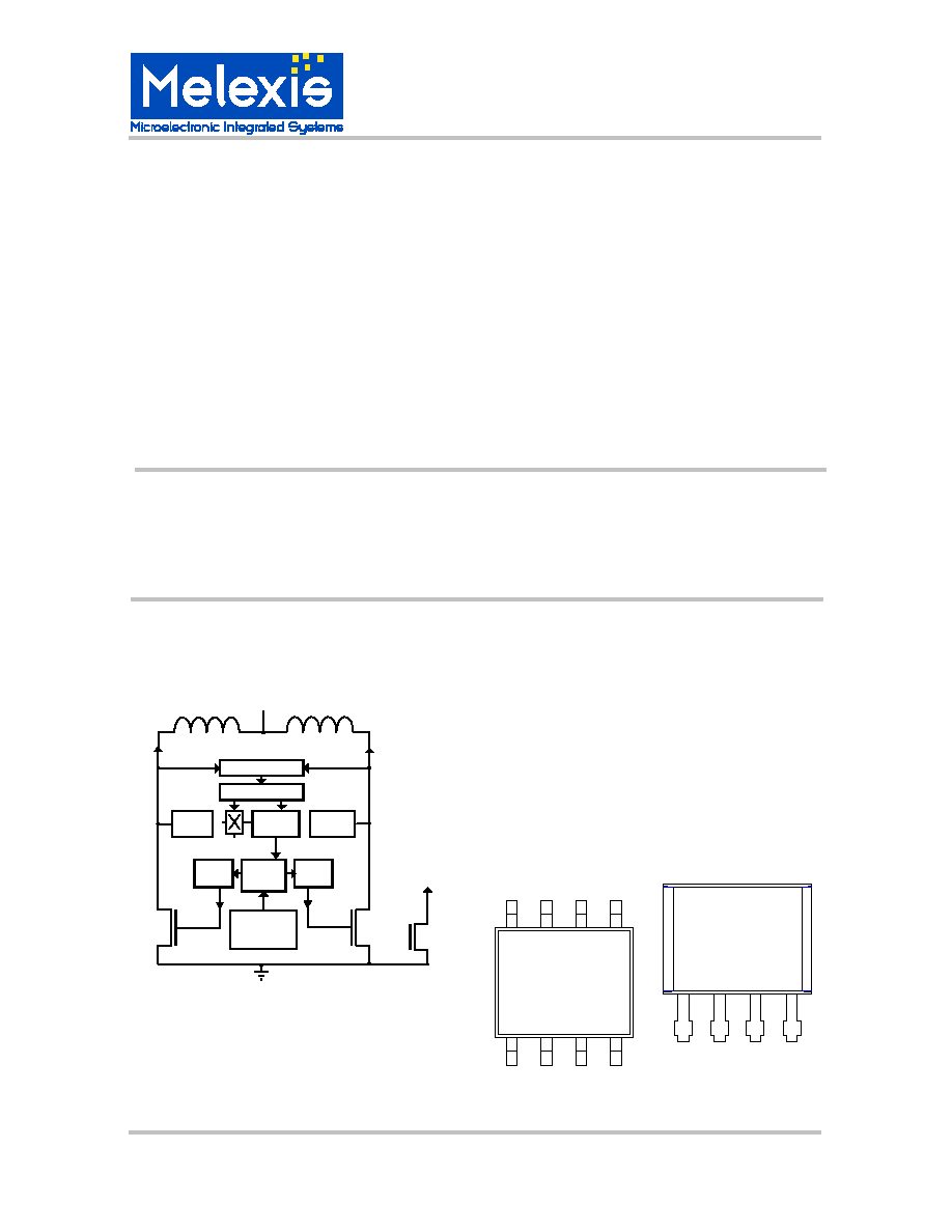
Functional Diagram
Locked-Rotor
Protection
Active
Clamp
Active
Clamp
Hall Amp
Gate
Drive
Gate
Drive
Logic
Out1
Out2
Vdd Recovery
Regulator
Fan Vdd
FG/RD
Description
The US90 and US91 provide one-chip solutions
for driving two-coil brushless DC cooling fans. A
novel Vdd recovery circuit allows the complete
three-wire fan control circuit to fit in a small four-
pin package. The US90 has an open-drain
tachometer output (FG) that follows the Hall
sensor latching output. The US91 has an open-
drain rotation detection output (RD) that is
normally low. It becomes high when the Hall
switching drops below 4Hz.
DC Package
VK Package
O
u
t
2
V
s
s
O
u
t
1
F
G
/
R
D
US90
XXXXX
4
3
2
1
5
6
7
8
1
2
3
4
US90
XXXXX
O
u
t
1
O
u
t
2
V
s
s
F
G
/
R
D

US90 / US91
24V Hall IC Fan Driver
3901090263
Page 2 of 13
Data Sheet
Rev. 004
May/03
TABLE OF CONTENTS
FEATURES AND BENEFITS............................................................................................................ 1
APPLICATIONS ............................................................................................................................... 1
ORDERING INFORMATION............................................................................................................. 1
FUNCTIONAL DIAGRAM................................................................................................................. 1
DESCRIPTION ................................................................................................................................. 1
1.
GLOSSARY OF TERMS ........................................................................................................ 3
2.
ABSOLUTE MAXIMUM RATINGS ......................................................................................... 3
3.
US90 / US91 ELECTRICAL SPECIFICATIONS ..................................................................... 4
4.
US90 / US91 MAGNETIC SPECIFICATIONS......................................................................... 4
5.
GENERAL DESCRIPTION..................................................................................................... 5
6.
UNIQUE FEATURES ............................................................................................................. 5
7.
PERFORMANCE GRAPHS ................................................................................................... 6
8.
APPLICATIONS INFORMATION ........................................................................................... 8
9.
APPLICATION COMMENTS.................................................................................................. 8
10.
RELIABILITY INFORMATION................................................................................................ 9
11.
ESD PRECAUTIONS ............................................................................................................. 9
12.
VK PACKAGE INFORMATION (4-PIN TO-92) ..................................................................... 10
13.
VK HALL SENSOR LOCATION........................................................................................... 10
14.
DC PACKAGE INFORMATION (8-PIN NARROW SOIC) ..................................................... 11
15.
DC HALL SENSOR LOCATION........................................................................................... 12
16.
DISCLAIMER....................................................................................................................... 13
US90 / US91
24V Hall IC Fan Driver
3901090263
Page 3 of 13
Data Sheet
Rev. 004
May/03
1. Glossary of Terms
MilliTesla (mT), Gauss: Units of magnetic flux density; 1 milliTesla = 10 Gauss
Two-Coil Fan: a fan with two coil windings, current alternates from 1 coil to the other depending on the
polarity of the magnetic field.
Two-wire Fan: A fan that has only two connections for the power supply plus and minus.
Three-wire Fan: A fan that has the two power supply connections, plus a tachometer or alarm signal
Locked rotor: The condition of a fan that has stopped spinning due to mechanical blockage
FG: Frequency Generator, or tachometer output signal
RD: Rotation Detection, or alarm output signal
2. Absolute Maximum Ratings
Fan Supply Voltage, V
DD
(overvoltage)
30V
Out1, Out2 Voltage
60V
FG / RD Voltage
28V
Peak Output Current, I
OUT
500mA
FG / RD Output Current
20mA
Operating Temperature Range, T
A
-40 to 85
�
C
Junction Temperature, T
j
125
�
C
Storage Temperature, T
s
-55 to 150
�
C
ESD Sensitivity (AEC Q100 002)
1.5KV
Magnetic Flux Density
No limit
Exceeding the absolute maximum ratings may cause permanent damage. Exposure to absolute-
maximum-rated conditions for extended periods may affect device reliability.
US90 / US91
24V Hall IC Fan Driver
3901090263
Page 4 of 13
Data Sheet
Rev. 004
May/03
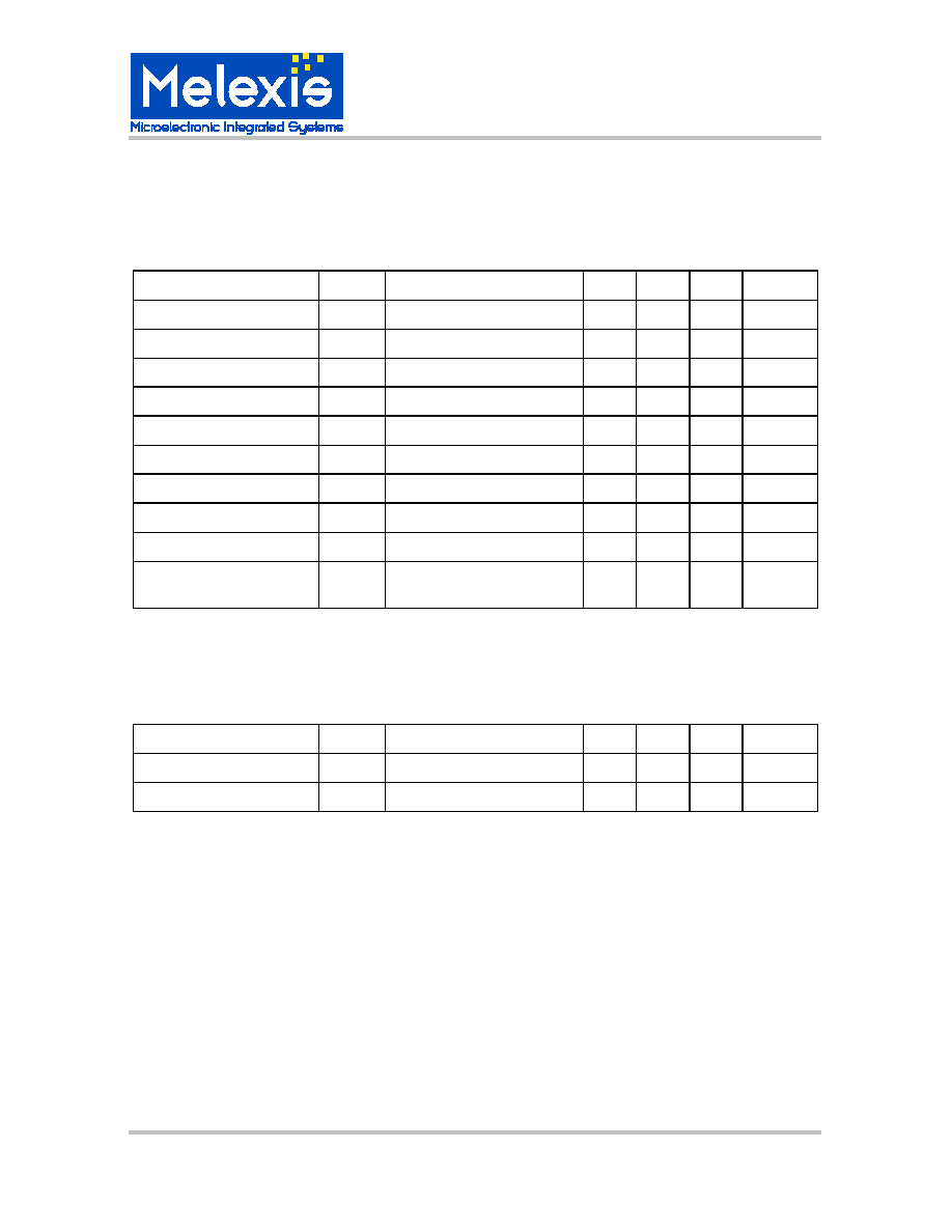
3. US90 / US91 Electrical Specifications
DC Operating Parameters T
A
= 25
o
C, V
DD
= 24V (unless otherwise specified)
Parameter
Symbol
Test Conditions
Min
Typ
Max
Units
Supply Voltage
V
DD
Operating
5
30
Volts
Supply Current
I
DD
2
4
mA
Output Saturation Voltage
V
dson
I
out
= 150mA
375
mV
Output Saturation Voltage
V
dson
I
out
= 250mA
625
mV
Output Current
I
load
Average continuous
250
mA
Thermal Resistance
R
th
one-sided PCB, zero LFPM
200
o
C/Watt
Locked-Rotor Period
t
on
0.25
S
Locked-Rotor period
t
off
1.5
S
Logic output On Voltage
V
low
FG, RD sink current = 10mA
250
500
mV
Logic output Off Current
I
off
FG, RD Vout=18V
0
10
uA
Output Switching delay
T
delay
"dead time" when both drivers
are off
200
uS
4. US90 / US91 Magnetic Specifications
DC Operating Parameters T
A
= 25
o
C, V
DD
= 24V (unless otherwise specified)
Parameter
Symbol
Test Conditions
Min
Typ
Max
Units
Operate Point
Bop
3.0
6.0
mT
Release Point
Brp
-6.0
-3.0
mT
Hysteresis
Hys
6.0
mT
Note:
1 mT = 10 Gauss
US90 / US91
24V Hall IC Fan Driver
3901090263
Page 5 of 13
Data Sheet
Rev. 004
May/03
5. General Description
The US90 and US91 provide a one-chip solution for 3-wire fans with two unipolar coil windings. The chip
contains the Hall-effect sensor, dynamic offset correction, and power drivers in a single package. The
output drivers pins are fully protected against switching transients. The logic output pin (FG or RD) is an
open-drain output.
6. Unique Features
The absence of a Vdd pin allows the chip to fit in a four-pin package, with two output drivers for the fan
coils and 1 logic output driver. The lack of a Vdd pin also provides some protection against reverse
voltage polarity of the power supply. The reverse current is limited by the resistance of the fan coils; the
reverse current will be double the normal stall current. In some fan designs this may be tolerable.
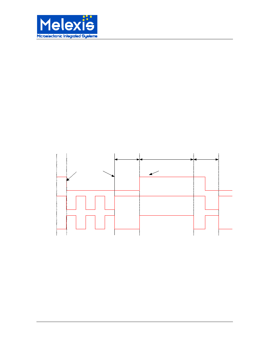
The built-in locked-rotor protection will automatically shut off the coil current when the rotor is
mechanically blocked, or the rotational speed drops below 60 RPM. The fan will try to restart every 1.5
seconds until the obstruction is clear. The On / Off cycling reduces the average stall current to 1/7
normal; this is enough to prevent overheating or damage to most fans. Both the US90 and US91 have
this feature.
Ton
Toff
Mechanical
Lock
`
Out1
RD
Current is
switched off
restart
Out2
Ton
High at
power on,
until 1st
transition