page
1
phone: 360.260.2468
l
sales: 800.736.0194
l
fax: 360.260.2469
email: sales@usdigital.com
l
website: www.usdigital.com
11100 ne 34th circle
l
vancouver, washington 98682 USA
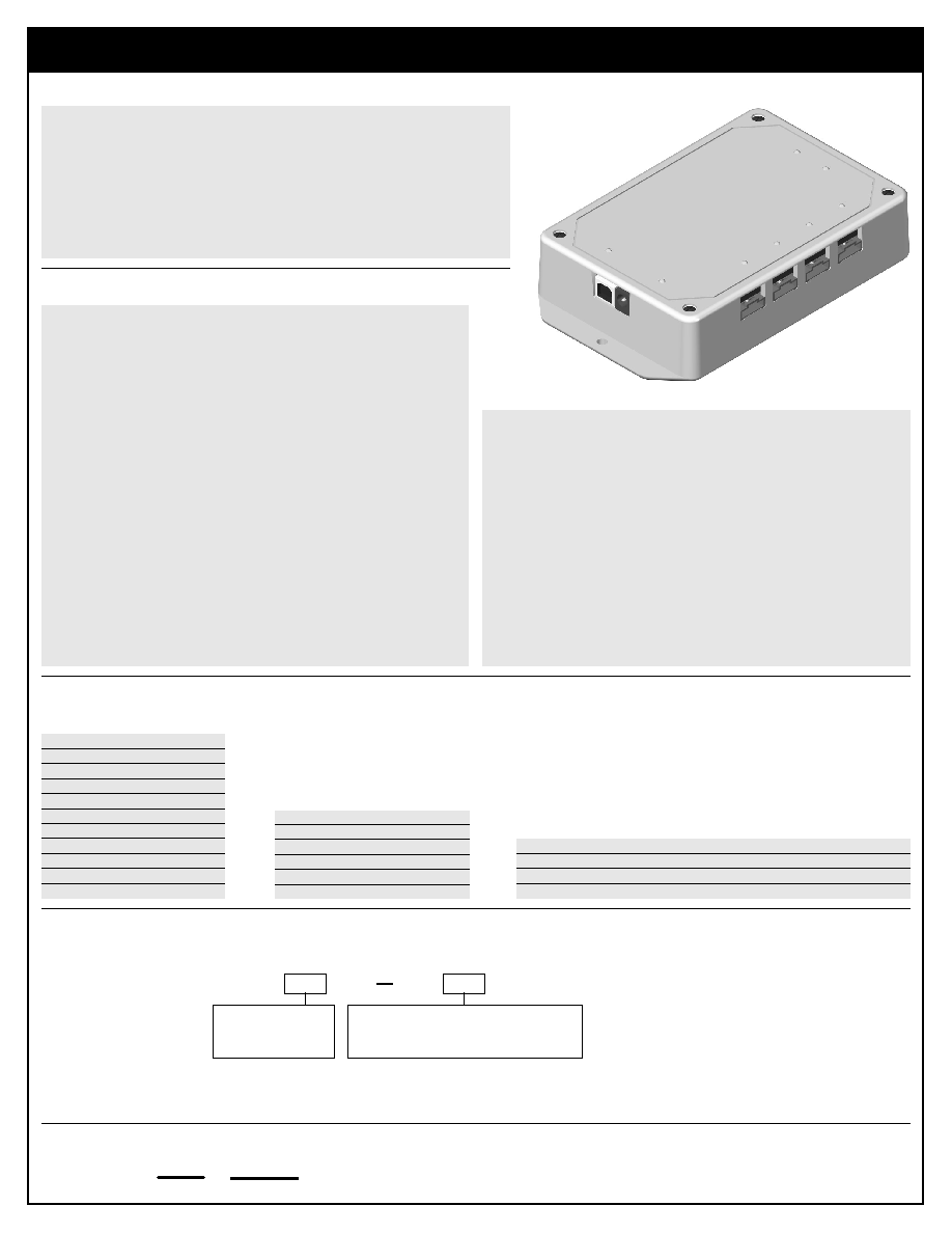
USB1
Encoder Data Acquisition USB Device
US
Digital
C o r p o r a t i o n
TM
Ordering Information:
Technical Data, Rev. 06.13.02, June 2002
All information subject to change without notice.
Features:
ÿ
Real-Time tracking of one to four incremental encoders and 8 digital inputs
ÿ
History buffer has programmable sample frequency from once per day to 1 kHz
ÿ
DIN rail mounting is available
ÿ
8 relay driver outputs
ÿ
LEDs show status of each encoder and bus activity
ÿ
Available with single-ended or differential encoder inputs
ÿ
Includes serial encoder interface (SEI) port for reading our absolute encoders
ÿ
Easy to use Windows drivers and demo software
ÿ
US Digital warrants its products against defects in materials and workmanship
for two years. See complete warranty for details.
Price:
$350 / 1
$315 / 10
$285 / 50
$255 / 100
$230 / 500
$210 / 1K
Cost Modifiers:
Add $10 for R-option
Subtract $5 for NP-option (no PS-9V)
Includes:
ÿ
PS-9V (power supply)
ÿ
USD-SW (software)
USB1 -
Part #:
Interface:
S = Single-ended.
D = Differential.
Options:
R = DIN rail (35mm wide) mounting.
NP = No power supply.
Description:
The USB1 is a data acquisition device designed to track up to 4 incremental
encoders and 8 digital inputs. Each of the 4 external encoders has a dedicated
24-bit real-time hardware up/down counter. The internal microcontroller then
reads and stores the value of all four counters, the 8 digital inputs, and a 32-
bit time stamp at a rate configured by the user. This historical buffer can be
downloaded to the PC using the USB interface at any convenient time, even
while continuing to store more samples in the internal circular buffer. The USB1
also includes the capability to use either encoder position changes or
combinations of digital inputs as triggering and/or storage qualification events.
Eight relay driver type digital outputs are provided along with an SEI port that
can read up to 15 US Digital absolute encoders per device. When a "1" is written
a digital output port bit, the driver is asserted and the corresponding port pin
is clamped to ground by a MOSFET transistor (it is an inverting 'open-collector'
configuration). The USB1 takes advantage of the robustness, speed, and easy
configurability of the Universal Serial Bus architecture while providing a simple
and consistent software interface for the encoders and inputs that it tracks.
The USB1 is intended for use with computers that have at least one free USB
port and are running the Windows 98 or Windows 2000 operating systems.
The USB1 is fully compatible with USB expansion hubs, allowing multiple USB1
units to be used on a single computer.
The USB1 is powered by a standard US Digital unregulated DC power supply
(PS-9V). The USB1 provides 5VDC power to the encoders and digital I/O
connectors. The USB1 may be instructed to retain configuration settings (but
not count values) when power is removed. If power is lost, the incremental
counters reset to zero.
The USB1 supports both indexed and non-indexed encoders in QUAD1,
QUAD2 or QUAD4. It provides independent, bi-directional counts on each of
its four incremental encoder channels, with counts from -8,388,608 to
8,388,607 at rates of up 230 KHz in quadrature mode. The USB1 command
protocol provides access to a control register for each channel, allowing
individually programmable count modes of Normal Count, Modulo-N, Non-
recycle, and Range Limit for each channel. The USB1 may be configured in
software to zero a channels counter when an encoder index signal is
asserted.
The SEI port on the USB1 is designed for US Digitals SEI-based products, such
as our A2 absolute encoders. The baud rate of the SEI port is fully program-
mable, and supports baud rates from 2400 to 57,600.
Parameter
Min.
Max.
Units
Storage Temperature
-40
100
∞C
Operating Temperature
0
70
∞C
Humidity (non-condensing)
0
95
%
Absolute Maximum Ratings:
S-option Encoder
Connector Pin-out:
Pin
Description
1
Ground
2
Index
3
A channel
4
+5VDC power
5
B channel
Pin
Description
1
Ground
2
Ground
3
Index-
4
Index+
5
A- channel
6
A+ channel
7
+5VDC power
8
+5VDC power
9
B- channel
10
B+ channel
D-option Encoder
Connector Pin-out: