UTC D965SS / D965ASS
NPN EPITAXIAL SILICON TRANSISTOR
UTC
UNISONIC TECHNOLOGIES CO. LTD
1
QW-R206-016,B
LOW VOLTAGE HIGH CURRENT
NPN TRANSISTOR
FEATURES
*Collector current up to 5A
* D965SS : Collector-Emitter voltage up to 20 V
* D965ASS : Collector-Emitter voltage up to 30 V
APPLICATIONS
* Audio amplifier
* Flash unit of camera
* Switching circuit
MARKING
(D965SS)
MARKING
(D965ASS)
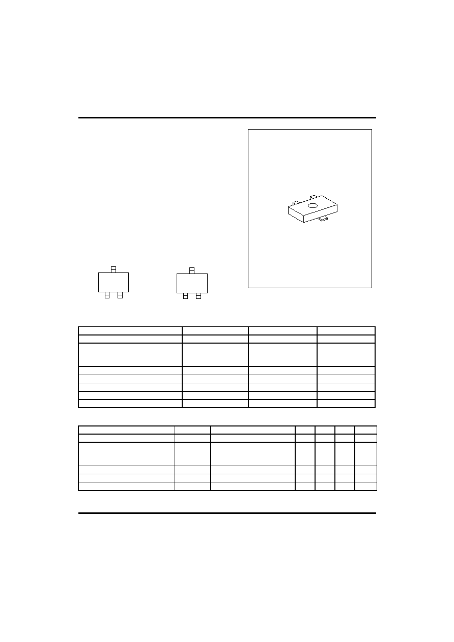
SOT-23
1
2
3
1: EMITTER 2: BASE 3: COLLECTOR
ABSOLUTE MAXIMUM RATINGS
( Ta=25
�C ,unless otherwise specified )
PARAMETER SYMBOL
RATING
UNIT
Collector-base voltage
V
CBO
40 V
Collector-emitter voltage
D965SS
D965ASS
V
CEO
20
30
V
Emitter-base voltage
V
EBO
7 V
Collector dissipation(Ta=25
�C)
Pc 750
mW
Collector current
Ic
5
A
Junction Temperature
T
j
150
�C
Storage Temperature
T
STG
-65 ~ +150
�C
ELECTRICAL CHARACTERISTICS
(Ta=25
�C,unless otherwise specified)
PARAMETER SYMBOL
TEST
CONDITIONS
MIN
TYP
MAX
UNIT
Collector-base breakdown voltage
BV
CBO
Ic=100
�A,I
E
=0 40
V
Collector-emitter breakdown voltage
D965SS
D965ASS
BV
CEO
Ic=1mA,I
B
=0
20
30
V
Emitter-base breakdown voltage
BV
EBO
I
E
=10
�A,Ic=0 7
V
Collector cut-off current
I
CBO
V
CB
=10V,I
E
=0
100
nA
Emitter cut-off current
I
EBO
V
EB
=7V,Ic=0
100
nA
D65
D65A
UTC D965SS / D965ASS
NPN EPITAXIAL SILICON TRANSISTOR
UTC
UNISONIC TECHNOLOGIES CO. LTD
2
QW-R206-016,B
DC current gain(note)
h
FE
V
CE
=2V,Ic=1mA
V
CE
=2V,Ic=0.5A
V
CE
=2V,Ic=2A
230
150
200
800
PARAMETER SYMBOL
TEST
CONDITIONS
MIN
TYP
MAX
UNIT
Collector-emitter saturation voltage
V
CE
(sat) Ic=3A,
I
B
= 0.1A
1
V
Current gain bandwidth product
f
T
V
CE
=6V,Ic=50mA
150
MHz
Output capacitance
Cob
V
CB
=20V,I
E
=0
f=1MHz
50
pF
CLASSIFICATION OF hFE2
RANK Q R S
RANGE 230-380 340-600 560-800
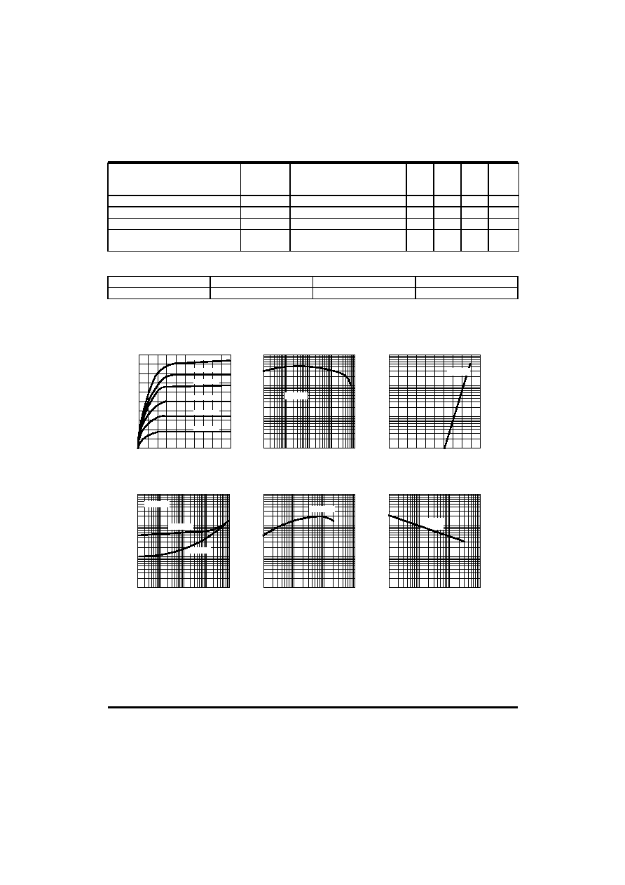
TYPICAL CHARACTERISTIC CURVES
Fig.1 Static characteristics
Collector-Emitter voltage ( V)
Ic,Collector current (A)
0
0.4
0.8
1.2
1.6
2.0
0
1.0
1.5
2.0
2.5
3.0
I
B
=0.5mA
I
B
=1.0mA
I
B
=1.5mA
I
B
=2.0mA
I
B
=2.5mA
I
B
=3.0mA
Fig.2 DC current Gain
Ic,Collector current (mA)
H
FE
, DC current Gain
10
2
10
1
10
0
10
3
10
4
10
3
10
2
10
1
10
-1
V
CE
=2V
Fig.3 Base-Emitter on Voltage
10
1
10
2
10
3
10
4
Ic,Collector current (mA)
Base-Emitter voltage (V)
0
0.2
0.4
0.6
0.8
1.0
V
CE
=2V
Ic,Collector current (mA)
10
4
10
3
10
2
10
1
10
0
Saturation voltage (mV)
10
1
10
2
10
3
10
4
Fig.4 Saturation voltage
Fig.5 Current gain-bandwidth
product
Fig.6 Collector output
Capacitance
V
CE
(sat)
V
BE
(sat)
Ic=10*I
B
Ic,Collector current (mA)
10
0
10
1
10
2
10
3
Current Gain-bandwidth
product,f
T
(MHz)
10
0
10
1
10
2
V
CE
=6V
Collector-Base voltage (V)
Cob,Capacitance (pF)
10
3
10
3
10
0
10
1
10
2
10
-1
10
0
10
1
10
2
f=1MHz
I
E
=0

UTC D965SS / D965ASS
NPN EPITAXIAL SILICON TRANSISTOR
UTC
UNISONIC TECHNOLOGIES CO. LTD
3
QW-R206-016,B
UTC assumes no responsibility for equipment failures that result from using products at values that
exceed, even momentarily, rated values (such as maximum ratings, operating condition ranges, or
other parameters) listed in products specifications of any and all UTC products described or contained
herein. UTC products are not designed for use in life support appliances, devices or systems where
malfunction of these products can be reasonably expected to result in personal injury. Reproduction in
whole or in part is prohibited without the prior written consent of the copyright owner. The information
presented in this document does not form part of any quotation or contract, is believed to be accurate
and reliable and may be changed without notice.