UTC UA9406
LINEAR INTEGRATED CIRCUIT
UTC
UNISONIC TECHNOLOGIES CO., LTD.
1
QW-R109-014,A
2-PHASE HALF-WAVE MOTOR
PREDRIVER
DESCRIPTION
The UTC UA9406 is a 2-phase, half-wave motor
predriver suited for fan motors.
FEATURES
*Lock detection and rotational speed sensing
mechanisms are built in.
*Compact 8-pin SOP package reduces the number of
external components required.
*Automatic restart when the motor lock is undone.
*Hall inputs have a hysteresis.
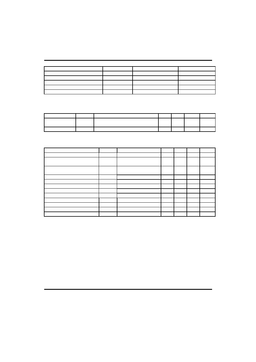
SOP-8
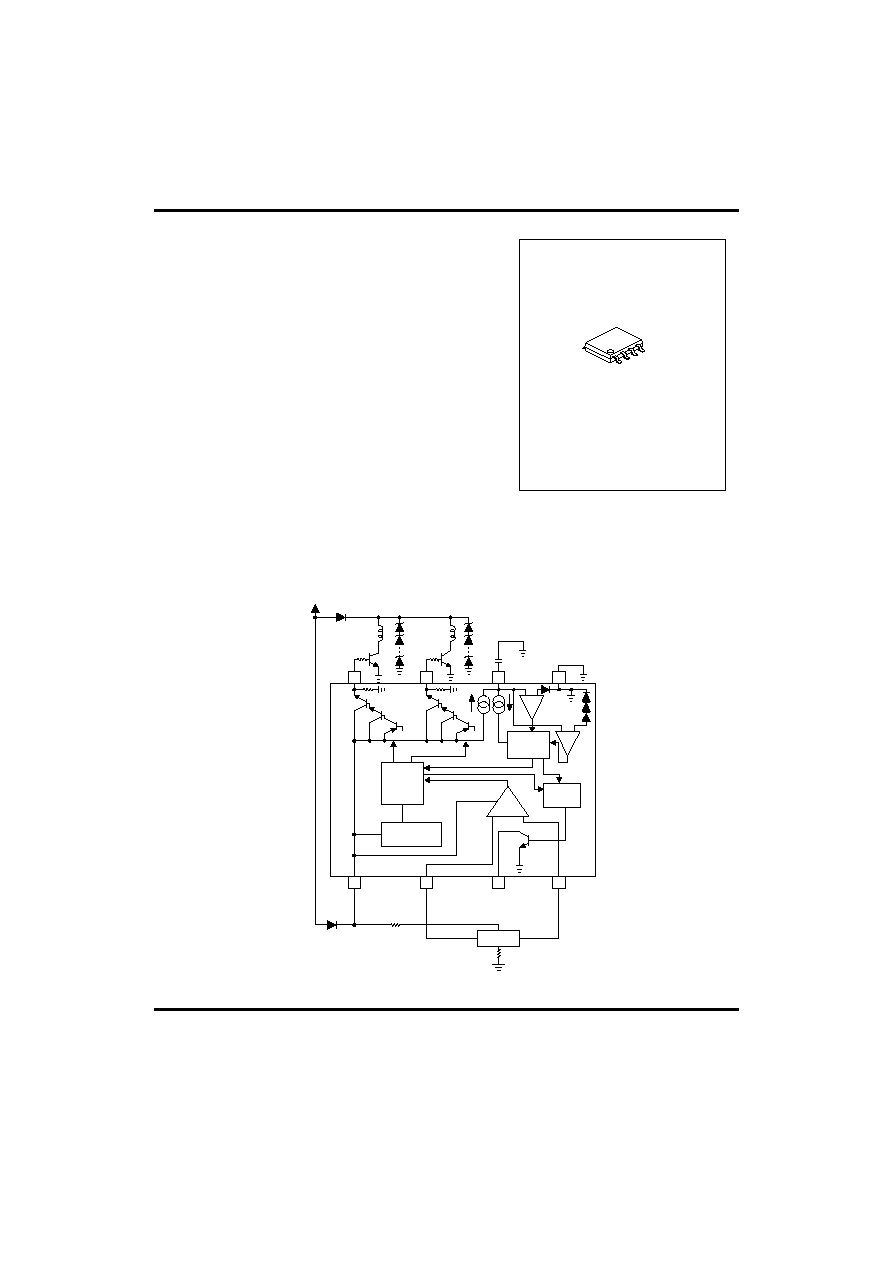
BLOCK DIAGRAM
1
2
3
4
Hall
REGULATOR
LOGIC
8
7
6
5
Vcc
Autornatic
reset
Rock
Det
Hall
amp
UTC UA9406
LINEAR INTEGRATED CIRCUIT
UTC
UNISONIC TECHNOLOGIES CO., LTD.
2
QW-R109-014,A
ABSOLUTE MAXIMUM RATINGS
PARAMETER SYMBOL
RATINGS UNIT
Applied voltage
Vcc
30
V
Power dissipation
Pd
550*
mW
Operating Temperature
Topr
-30 ~ +75
Storage Temperature
Tstg
-55 ~ +125
Output current
Io
Max.
70
mA
* Reduced by 5.5mW for each increase in Ta of 1 over 25
When mounted on a glass epoxy board (50�50�1.6mm)
OPERATING POWER SUPPLY VOLTAG (Ta=25)
PARAMETER SYMBOL
TEST
CONDITIONS
MIN
TYP MAX UNIT
Applied voltage
Vcc
Operate within the allowable power
Dissipation for �30<Ta<75
4 28 V
Input voltage*
V
BH
1.0
Vcc-0.5
V
*Input voltage range includes the amplitude of signal
ELECTRICAL CHARACTERISTICS
(Unless otherwise noted, Ta=25, Vcc=12V)
PARAMETER SYMBOL
TEST
CONDITIONS
MIN
TYP
MAX
UNIT
Supply current
Icc
When output is OFF
3.2
5.0
mA
Hall amplifier input hyseresis (+)
V
hys
+
Pin2 voltage with respect to
pin4 voltage, V
B
=6V
3 15
mV
Hall amplifier input hysteresis (-)
V
hys
-
Pin2 voltage with respect to
pin4 voltage, V
B
=6V
-3 -15
mV
Pin6 charge current
I
6c
V6pin=1.5V
2.0 3.45 5.25 A
Pin6 discharge current
I
6d
V6pin=1.5V
0.35
0.80 1.45 A
Pin6 charge/discharge ratio
r
cd
I
6c
/I
6d
3
4.5
8
Pin6 clamp voltage
V
6CL
2.2 2.6 3.0 V
Pin6 comparator voltage
V
6cp
0.4 0.6 0.8 V
Pin7 Output high level voltage
V
7H
Io=10mA
10 10.5
V
Pin8 Output high level voltage
V
8H
Io=10mA
10 10.5
V
Pin3 Output low level voltage
V
3L
I
3L
=5.0mA
0.5
V
Pin3 current capacity
I
3
V
3L
=2.0V 8.0
mA

UTC UA9406
LINEAR INTEGRATED CIRCUIT
UTC
UNISONIC TECHNOLOGIES CO., LTD.
3
QW-R109-014,A
LOCK DETECTION
The automatic restart circuit detects a motor lock condition and automatically turns off the output current. When
the lock condition is cleared, the IC automatically restarts and allow the motor to run.
In the UTC UA9406, automatic restart is performed in the following manner. A motor lock condition is detected
when the Hall signal stops switching. The output is ON when pin 6 is being charged, and OFF when pin 6 is being
discharged. Pin 3 is ON during normal operation, and OFF when the motor is locked. Pin 3 is an open collector
output.
Hall input
Motor output
6 pin
3pin L
Motor
locked
Motor lock detected
High
t
ON
*
t
OFF
**
Pin6
comparator
voltage
Motor lock
cleared
Reverts to normal operation
Fig.1
OFF
Pin6
clamp
voltage
ON
Output ON time (t
ON
) and OFF time (t
OFF
) determined by the pin6 capacitor where
t
ON
=
C (V
6CL
-V
6CP
)
I
6C
(sec)
t
OFF
=
C (V
6CL
-V
6CP
)
I
6d
(sec)
C is the capacitance of the pin-6 external capacitor
V
6CL
is the pin6 clamp voltage
V
6CP
is the pin6 comparator voltage
I
6C
is the pin6 charge current
I
6d
is the pin6 discharge current
OPERATION NOTES
(1) The lock detection output pin (pin 3) may maintain
HIGH level for a few hundred milliseconds when the power is turned on.
Power
3 pin
A few hundred millseconds
Fig.2
UTC UA9406
LINEAR INTEGRATED CIRCUIT
UTC
UNISONIC TECHNOLOGIES CO., LTD.
4
QW-R109-014,A
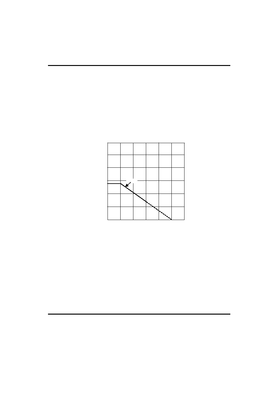
(2) Allowable power dissipation
The allowable power dissipation is plotted against ambient temperature in Fig. 3.
(3) Power dissipation
Power consumed in the IC can be calculated from the following equation:
P
C
= P
C1
+P
C2
+P
C3
(1) PC1 is power consumed by the circuit current.
P
C1
= V
CC
�
I
CC
(2) PC2 is the output current consumption.
P
C2
= (V
CC
�
V
OH
)�I
O
V
OH
is the HIGH level voltage of pins 7 and 8. Power dissipation can be reduced by raising the hfe-rank of the
external output transistor and thereby reducing the I
O
value.
(3) P
C3
is power consumed by pin 3.
P
C3
= V
3L
�
I
3
Where V
3L
is the pin-3 LOW level voltage and I
3
is the pin-3 current. Make sure that your application does not
exceed the allowable power dissipation of the IC.
0.6
0.8
AMBIENT TEMPERATURE, Ta ()
25
0.2
POWER DISSIPATION, Pd
(W)
0.4
50
1.0
UA9406
75
100
125
Fig.3
150

UTC UA9406
LINEAR INTEGRATED CIRCUIT
UTC
UNISONIC TECHNOLOGIES CO., LTD.
5
QW-R109-014,A
ELECTRICAL CHARACTERISTIC CURVES
0
10
15
3 pin SUPPLY VOLTAGE (V)
2
I
3L
(mA
)
5
4
20
Vcc=12V
6
8
10
12
Current capacity vs.supply voltage
for pin 3
11
7,8 pin OUTPUT CURRENT (mA)
0
7,
8 pin OU
TP
U
T
V
O
LTA
G
E
(V
)
10
20
12
Vcc=12V
40
60
80
Output voltage vs.output current for
pins 7 and 8
UTC assumes no responsibility for equipment failures that result from using products at values that
exceed, even momentarily, rated values (such as maximum ratings, operating condition ranges, or
other parameters) listed in products specifications of any and all UTC products described or contained
herein. UTC products are not designed for use in life support appliances, devices or systems where
malfunction of these products can be reasonably expected to result in personal injury. Reproduction in
whole or in part is prohibited without the prior written consent of the copyright owner. The information
presented in this document does not form part of any quotation or contract, is believed to be accurate
and reliable and may be changed without notice.