UTC 2SD882S NPN EPITAXIAL SILICON TRANSISTOR
UTC
UNISONIC TECHNOLOGIES CO. LTD
1
QW-R201-024,A
MEDIUM POWER LOW VOLTAGE
TRANSISTOR
FEATURES
*High current output up to 3A
*Low saturation voltage
*Complement to 2SB772S
APPLICATIONS
* Audio power amplifier
* DC-DC convertor
* Voltage regulator
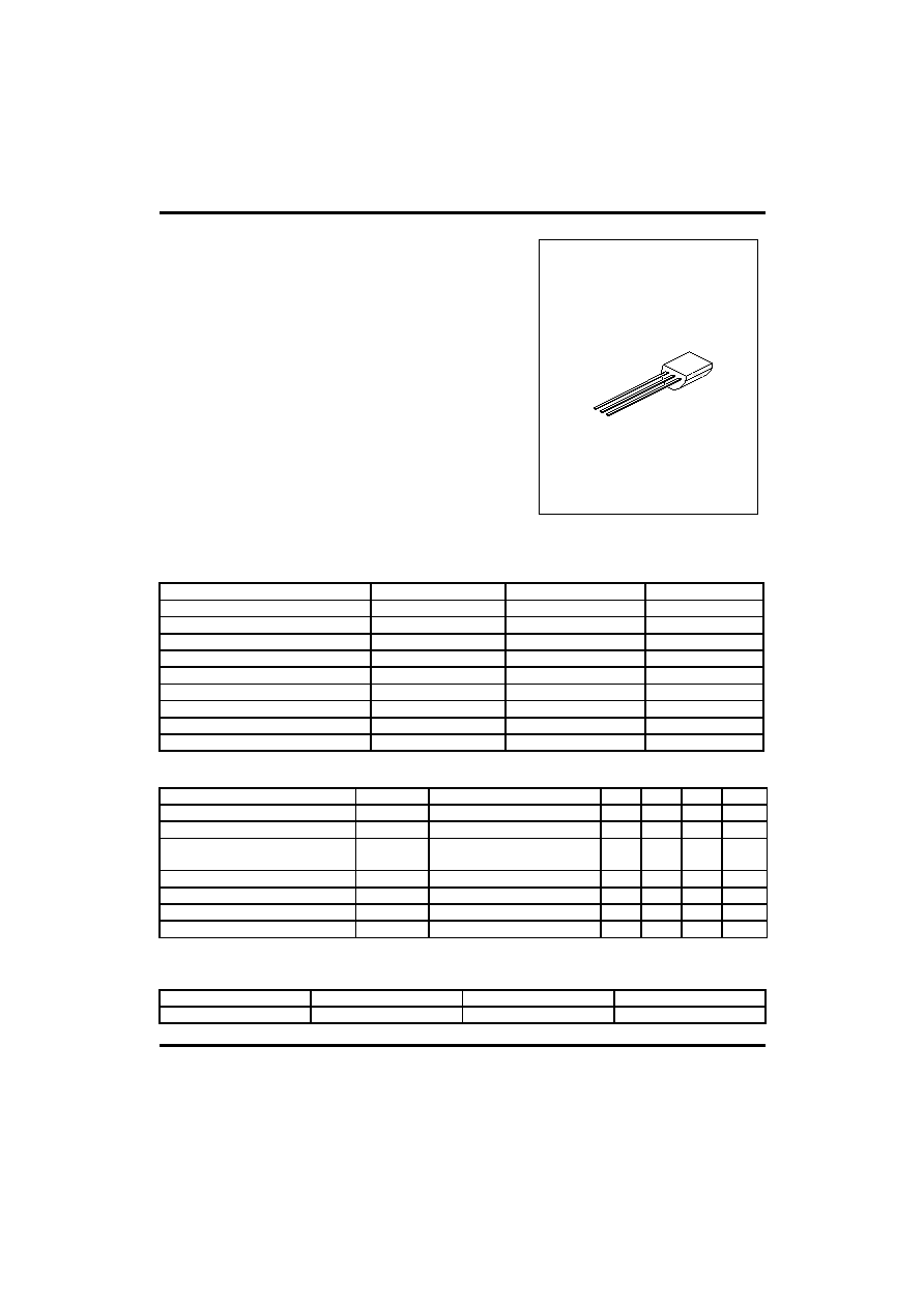
TO-92
1
1:EMITTER 2:COLLECTOR 3:BASE
ABSOLUTE MAXIMUM RATINGS
(Ta=25
∞C ,unless otherwise specified )
PARAMETERS SYMBOL
RATING
UNIT
Collector-base voltage
V
CBO
40 V
Collector-emitter voltage
V
CEO
30 V
Emitter-base voltage
V
EBO
5 V
Collector dissipation( Ta=25
∞C) Pc
0.5 W
Collector current(DC)
Ic
3
A
Collector current(PULSE)
Ic
7
A
Base current
I
B
0.6
A
Junction Temperature
T
j
150
∞C
Storage Temperature
T
STG
-55 ~ +150
∞C
ELECTRICAL CHARACTERISTICS
(Ta=25
∞C,unless otherwise specified)
PARAMETER SYMBOL
TEST
CONDITIONS
MIN
TYP
MAX
UNIT
Collector cut-off current
I
CBO
V
CB
=30V,I
E
=0
1000
nA
Emitter cut-off current
I
EBO
V
EB
=3V,Ic=0
1000
nA
DC current gain(note 1)
h
FE1
h
FE2
V
CE
=2V,Ic=20mA
V
CE
=2V,Ic=1A
30
100
200
150
400
Collector-emitter saturation voltage
V
CE
(sat) Ic=2A,I
B
=0.2A
0.3
0.5
V
Base-emitter saturation voltage
V
BE
(sat) Ic=2A,I
B
=0.2A
1.0
2.0
V
Current gain bandwidth product
f
T
V
CE
=5V,Ic=0.1A
80
MHz
Output capacitance
Cob
V
CB
=10V,I
E
=0,f=1MHz
45
pF
Note 1:Pulse test:PW<300
µs,Duty Cycle<2%
CLASSIFICATION OF hFE2
RANK Q P E
RANGE 100-200 160-320 200-400

UTC 2SD882S NPN EPITAXIAL SILICON TRANSISTOR
UTC
UNISONIC TECHNOLOGIES CO. LTD
2
QW-R201-024,A
TYPICAL PARAMETERS PERFORMANCE
Fig.1 Static characteristics
-Collector-Emitter voltage(V)
-Ic,
C
o
llect
or current
(A)
0
4
8
12
16
20
0
0.4
0.8
1.2
1.6
Tc,Case Temperature(∞C)
-IB=1mA
-IB=2mA
-IB=3mA
-IB=4mA
-IB=5mA
-IB=6mA
-IB=7mA
-IB=8MA
-IB=9mA
Fig.2 Derating curve of safe
operating areas
- Ic De
ra
ti
n
g
(
%)
200
150
100
50
0
-50
0
50
100
150
S/b
lim
ited
D
iss
ip
atio
n li
m
ite
d
Tc,Case Temperature(∞C)
200
150
100
50
0
-50
Fig.3 Power Derating
Power Dissipat
ion(W
)
0
4
8
12
Fig.4 Collector Output
capacitance
-Collector-Base Voltage(v)
O
u
t
put
C
apacit
ance(
pF)
10
0
10
-1
10
-2
10
-3
10
1
10
2
10
3
10
0
I
E
=0
f=1MHz
Fig.5 Current gain-
bandwidth product
F
T
(
M
H
z
)
,
C
u
r
r
ent
gain-
bandw
idt
h
pr
oduct
10
1
10
2
10
3
10
0
V
CE
=5V
Collector-Emitter Voltage
-I
c,
C
o
llector current
(A)
Fig.6 Safe operating area
Ic(max),DC
Ic(max),Pulse
10m
S
1m
S
0.1
mS
Ic,Collector current(A)
Fig.7 DC current gain
-Ic,Collector current(mA)
-Ic,Collector current(mA)
Fig.8 Saturation Voltage
DC c
u
rre
n
t
Ga
i
n
,H
FE
10
1
10
2
10
3
10
0
-Sat
urat
ion Volt
age(mV)
V
CE
=-2V
V
CE
(sat)
V
BE
(sat)
10
-2
10
-1
10
0
10
1
10
-2
10
-1
10
0
10
1
10
0
10
1
10
2
10
0
10
1
10
2
10
3
10
4
10
0
10
1
10
2
10
3
10
4
10
0
10
1
10
2
10
3
10
4
I
B
=8mA
I
B
=8mA
UTC assumes no responsibility for equipment failures that result from using products at values that
exceed, even momentarily, rated values (such as maximum ratings, operating condition ranges, or
other parameters) listed in products specifications of any and all UTC products described or contained
herein. UTC products are not designed for use in life support appliances, devices or systems where
malfunction of these products can be reasonably expected to result in personal injury. Reproduction in
whole or in part is prohibited without the prior written consent of the copyright owner. The information
presented in this document does not form part of any quotation or contract, is believed to be accurate
and reliable and may be changed without notice.