UTC HE8550 PNP EPITAXIAL SILIC ON TRANSISTOR
UTC
UNISONIC TECHNOLOGIES CO. LTD
1
QW-R201-010,A
LOW VOLTAGE HIGH CURRENT
SMALL SIGNAL PNP TRANSISTOR
DESCRIPTION
The UTC HE8550 is a low voltage high current small
signal PNP transistor, designed for Class B push-pull
2W audio amplifier for portable radio and general purpose
applications.
FEATURES
*Collector current up to 1.5A
*Collector-Emitter voltage up to 25 V
*Complimentary to UTC HE8050
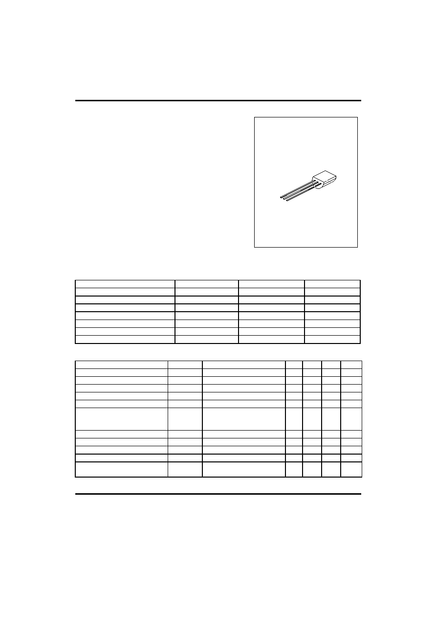
TO-92
1
1:EMITTER 2:COLLECTOR 3:BASE
ABSOLUTE MAXIMUM RATINGS
(Ta=25
∞C, unless otherwise specified)
PARAMETER SYMBOL
VALUE
UNIT
Collector-Base Voltage
V
CBO
-40 V
Collector-Emitter Voltage
V
CEO
-25 V
Emitter-Base Voltage
V
EBO
-6 V
Collector Dissipation(Ta=25
)
Pc 1
W
Collector Current
Ic
-1.5
A
Junction Temperature
T
j
150
∞C
Storage Temperature
T
STG
-65 ~ +150
∞C
ELECTRICAL CHARACTERISTICS
(Tj=25
∞C, unless otherwise specified)
PARAMETER SYMBOL
TEST
CONDITIONS
MIN
TYP
MAX
UNIT
Collector-Base Breakdown Voltage
BV
CBO
Ic=-100
µA,I
E
=0 -40
V
Collector-Emitter Breakdown Voltage
BV
CEO
Ic=-2mA,I
B
=0 -25
V
Emitter-Base Breakdown Voltage
BV
EBO
I
E
=-100
µA,Ic=0 -6
V
Collector Cut-Off Current
I
CBO
V
CB
=-35V,I
E
=0
-100
nA
Emitter Cut-Off Current
I
EBO
V
EB
=-6V,Ic=0
-100
nA
DC Current Gain(note)
h
FE1
h
FE2
h
FE3
V
CE
=-1V,Ic=-5mA
V
CE
=-1V,Ic=-100mA
V
CE
=-1V,Ic=-800mA
45
85
40
170
160
80
500
Collector-Emitter Saturation Voltage
V
CE
(sat) Ic=-800mA,I
B
=-80mA
-0.28
-0.5
V
Base-Emitter Saturation Voltage
V
BE
(sat) Ic=-800mA,I
B
=-80mA
-0.98
-1.2
V
Base-Emitter Voltage
V
BE
V
CE
=-1V,Ic=-10mA
-0.66
-1.0
V
Current Gain Bandwidth Product
f
T
V
CE
=-10V,Ic=-50mA 100
190
MHz
Output Capacitance
Cob
V
CB
=-10V,I
E
=0
f=1MHz
9.0 pF
UTC HE8550 PNP EPITAXIAL SILIC ON TRANSISTOR
UTC
UNISONIC TECHNOLOGIES CO. LTD
2
QW-R201-010,A
CLASSIFICATION OF hFE
RANK C D E
RANGE 120-200 160-300 250-500
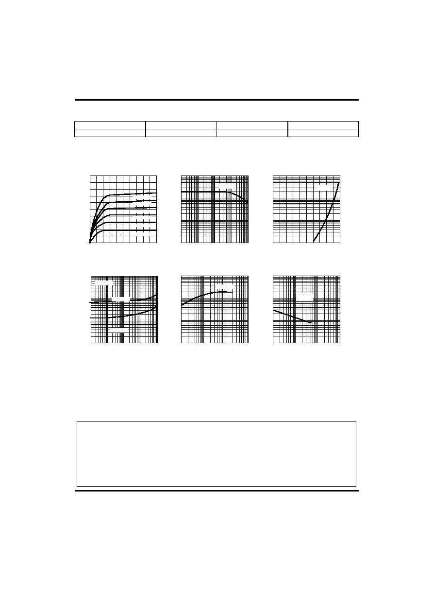
TYPICAL PERFORMANCE CHARACTERISTICS
Fig.1 Static characteristics
Collector-Emitter voltage ( V)
Ic,Co
lle
cto
r
cu
r
r
e
n
t
(
m
A)
-0
-0.4
-0.8
-1.2
-1.6
-2.0
0
-0.1
-0.2
-0.3
-0.4
-0.5
I
B
=-0.5mA
I
B
=-1.0mA
I
B
=-1.5mA
I
B
=-2.0mA
I
B
=-2.5mA
I
B
=-3.0mA
Fig.2 DC current Gain
Ic,Collector current (mA)
H
FE
, DC current Gain
10
2
10
1
10
0
10
3
-10
3
-10
2
-10
1
-10
0
-10
-1
V
CE
=-1V
Fig.3 Base-Emitter on Voltage
Ic,Co
lle
cto
r
cu
r
r
e
n
t
(
m
A)
Base-Emitter voltage (V)
0
-0.2
-0.4
-0.6
-0.8
-1.0
V
CE
=-1V
Ic,Collector current (mA)
S
a
t
u
rat
i
on v
o
lt
age (mV
)
-10
1
-10
2
-10
3
-10
4
Fig.4 Saturation voltage
Fig.5 Current gain-bandwidth
product
Fig.6 Collector output
Capacitance
V
CE
(sat)
V
BE
(sat)
Ic=10*I
B
Ic,Collector current (mA)
10
3
Current
G
a
in-bandwidt
h
produc
t
,
f
T
(MHz)
10
0
10
1
10
2
V
CE
=-10V
Collector-Base voltage (V)
Cob,
Capac
it
anc
e (pF)
10
3
10
0
10
1
10
2
f=1MHz
I
E
=0
-10
0
-10
1
-10
2
-10
3
-10
3
-10
2
-10
1
-10
0
-10
-1
-10
0
-10
1
-10
2
-10
3
-10
0
-10
1
-10
2
-10
3
UTC assumes no responsibility for equipment failures that result from using products at values that
exceed, even momentarily, rated values (such as maximum ratings, operating condition ranges, or
other parameters) listed in products specifications of any and all UTC products described or contained
herein. UTC products are not designed for use in life support appliances, devices or systems where
malfunction of these products can be reasonably expected to result in personal injury. Reproduction in
whole or in part is prohibited without the prior written consent of the copyright owner. The information
presented in this document does not form part of any quotation or contract, is believed to be accurate
and reliable and may be changed without notice.